

Page 1
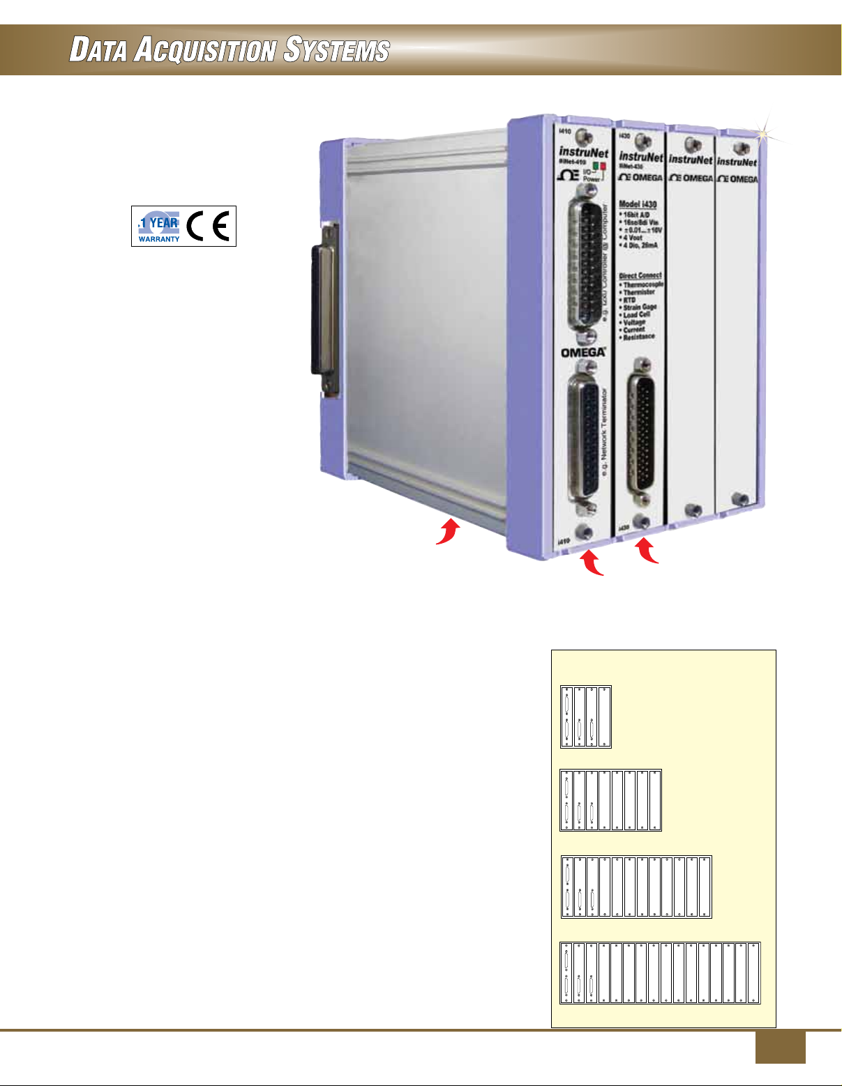
Expandable Modular Data Acquisition System
iNET-400 Series
U USB 2.0 High Speed Data
Acquisition Hardware for
Windows® ≥XP SP2, Vista, 7 or
8 (XP/VS/7/8)
U Analog and Digital Input
and Outputs
U Free instruNet World Software
U Directly Connects to
Thermocouple, RTD,
Thermistor, Strain Gage,
Load Cell, Voltage,
Current, Resistance and
Accelerometer Input’s
U Reduce Noise by Placing Boxes
Near Sensors and
up to 1000' From Noisy
Computer
U Digitize Any Combination
of Channels at 166,000 Samples
Per Second Aggregate
U Each Channel has
Independently Programmable
Analog Filters, Integration
Time, Voltage Range, and
Sample Rate; Programmable
Digital Filters on All Channels
(LP, HP, BP, BS)
The iNET-400 system is a low
cost card cage that attaches to
Windows computers via USB 2.0.
The advantage of a card cage
is that you can select which I/O
modules to install as needed to build
a customized system. The instruNet
card cage typically has one A/D
measurement module and additional
modules provide signal conditioning.
The conditioned analog signal is
routed to the A/D module via the
backplane.
This is dramatically different from
comparable systems which place
A/D measurement electronics on
each module. The advantage of the
iNET-400 topology is cost. After the
1st module is installed, additional
iNET-400 channels are conditioned
at a very low cost per channel.
Shown smaller
than actual size.
iNET-400
card cage.
iNET-400 measurement modules
have universal inputs that enable
one to directly connect each channel
to one of: thermocouple, thermistor,
strain gage, load cell, counter/timer,
RTD, voltage, current, resistance and
accelerometer.
Absolute accuracy for all of these
sensor types is specified. In some
cases, the end user adds an external
shunt resistor. The advantage of
universal inputs is cost.
Low Cost 4/8/12/16-Slot
Card Cages
The iNET-400 card cage provides
4 slots, and multiple iNET-400’s
can be bolted together by the end
user, side-by-side, to create an
8, 12, or 16 slot system. In many
applications, one iNET-400
with 4 slots is sufficient.
iNET-430
iNET-410
4/8/12/16-slot card cages
4 slots
8 slots
12 slots
16 slots
1
Page 2
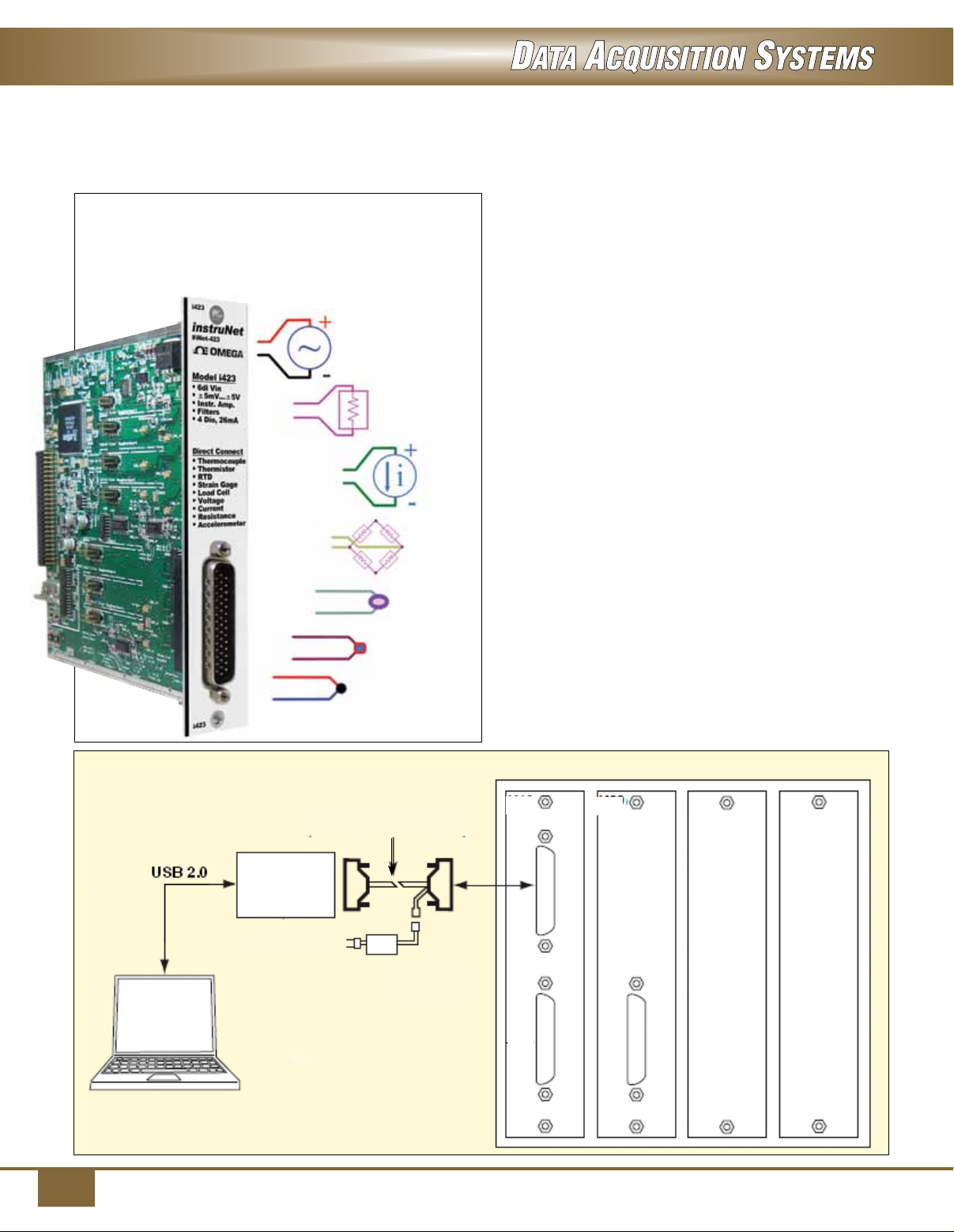
Connect Directly to Common Sensors
Data acquisition cards connect directly to thermocouple,
thermistor, strain gage, load cell, counter/timer, RTD,
voltage, current, resistance and accelerometer.
Voltage
Resistance
Current
Strain Gage
RTD
Thermistor
The iNET-400 card cage is 15 D x 11 W x 14 cm H
(6 x 4.5 x 5.6") in size. The slots are numbered such
that #1 is the left-most slot, #2 is to the right of #1,
and so forth and so on. Cards are held into position
with jackscrews that are tightened with a slotted
screwdriver. Slot #1 is a special slot and is used to
interface to a computer.
The iNET-410 card slides into slot #1 and then cables
to the computer via a DB25 cable that connects to an
instruNet controller. Also, an iNET-300 Power Adaptor
cable is used to route power from an iNET-312-8
desktop power supply to the iNET-410 interface card
in slot #1, which in turn routes that power to the card
cage backplane (i.e. pcb at back of card cage that
attaches to all cards). This is illustrated in the below
diagram.
The iNET-400 Card Cage needs at least one
iNET-430 A/D card if analog voltages are to be
measured. The iNET-430 cards includes an A/D
converter and serves this purpose.
The iNET-420 and iNET-423 cards contain various
signal conditioning circuits and route signals along
the backplane to the iNET-430 for measurement.
This happens automatically and does not require
programmer intervention, other than insertion of cards
and attaching end user signals to the card’s front
panel connectors.
Windows PC
iNET-300 cable
(included with iNET-312-8)
iNET-240
110 to 220 Vac
Thermocouple
iNET-312-8
Power supply
i410
i430
2
Page 3
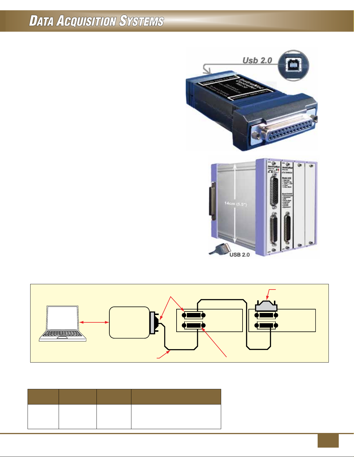
iNET-240 instruNet DSP Card
Each instruNet Network is controlled by an instruNet
DSP controller card that attaches to a Microsoft
Windows computer. The iNET-240 attaches to a free
USB 2.0 high speed port (requires Windows ≥ XP
SP2). Each Controller is an independent computer in
itself that utilizes a powerful 32-bit DSP processor and
onboard RAM to control all aspects of data acquisition
along its network. All real-time tasks are off-loaded
to this processor, therefore the host computer is not
burdened with real-time issues. Between 1 and 4
controllers can be installed, space permitting, since
each controller operates independently.
Connect up to 8 iNET-400 Card Cages
Each instruNet network supports up to 8 instruNet
iNET-400 card cages.
instruNet Network
These devices are connected in a daisy-chain
configuration to form a chain of Devices. Each
network can be up to 300 meters long. All networks
are anchored with an instruNet Terminator at the far
end, and an instruNet Controller at the near end. This
makes instruNet a cost effective method for designing
large scale, high speed, multi-channel data acquisition
systems.
iNET-240
USB controller,
shown smaller
than actual size
DB-25 connector (male)
Windows PC
iNET-240
instruNet
controller
DB-25 cable DB-25 connector (female)
iNET-400
card cage
Summary of Computers
Compatible with instruNet
Controller
Model No. Type Size Computer Required
iNET-240 USB 2.0 4 x 2 x 1" 32-bit or 64-bit Windows ≥ XP SP2,
Vista, 7 or 8 (XP/VS/7/8) Computer
with 1 available USB 2.0 High Speed
port (480Mbaud).
instruNet terminator
iNET-400
card cage
instruNet Version ≥ 3.0 software
requires Windows XP, Vista, 7 or
8 (XP/VS/7/8) computer with at least
256MB of RAM Memory and at
least 256 MB of free disk space. The
iNET-240 USB controller requires
32-bit or 64-bit Windows XP SP2
(service pack #2) or newer.
3
Page 4
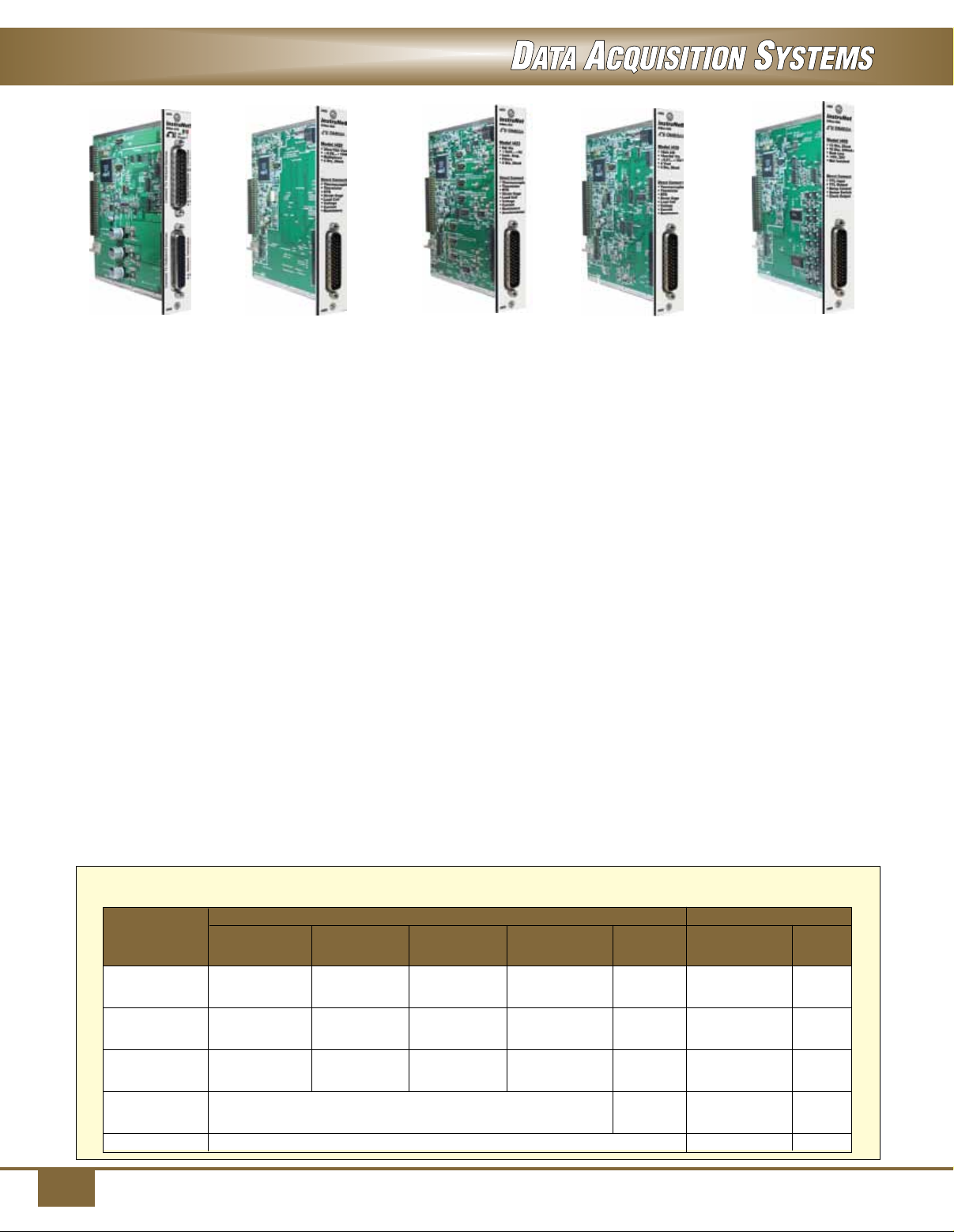
iNET-400 Series Data Acquisition Cards
iNET-410
iNET-420
iNET-423
iNET-410 Communications Card
The iNET-410 communications card connects an
iNET-400 card cage to a Windows computer via an
instruNET iNET-240 USB controller. The iNET-410
plugs into the left-most slot (slot #1) of an iNET-400
card cage. One and only one iNET-410 is required
per iNET-400 card cage when working with instruNet
controllers. The iNET-410 provides the following
features:
• Two DB25 connectors allow daisy-chaining multiple
iNET-400 card cage devices to one instruNet
controller card.
• Front panel red power light shows presence of 5V,
12V and -12V power.
• Front panel green I/O light blinks when computer
communicates with card cage.
• Includes one DB25 male to female 3 m (10') cable.
iNET-420 Analog I/O Module
The iNET-420 provides 20 single-ended (SE)/10
differential (DI) voltage input channels and 4 universal
digital I/O (20 mA sink, -10V to 30V) and requires
the iNET-430 A/D module to measure voltages. The
iNET-420 connects directly to voltage, thermocouple,
thermistor, RTD, load cell, strain gage, potentiometer,
current and resistance inputs.
iNET-423 Analog I/O Module
The iNET-423 provides 6 differential (DI) voltage
input channels, 4 universal digital I/O (20 mA sink,
-10 to 30V) and requires the iNET-430 A/D module
iNET-430 iNET-460
to measure voltages. The iNET-423 connects directly
to voltage, thermocouple, thermistor, RTD, load cell,
strain gage, potentiometer, current and resistance
inputs. Each input channel passes through it’s own
amplifier with a software selectable gain of 1 or 64 and
optional low pass filter. The 8-pole iNET-500 analog
low pass Butterworth filter daughter board is ideal
for anti-aliasing. Between one and six filter daughter
boards can be installed onto each iNET-423 card (one
per channel). There are four different analog low pass
filters, each with a different cut off frequency:
iNET-500-380HZ, iNET-500-1KHZ, iNET-500-3300HZ
and iNET-500-10KHZ.
iNET-430 A/D Module
The iNET-430 provides 16 single-ended (SE)/8
differential (DI) voltage input channels with a 16-bit
A/D converter, 2 precision analog voltage outputs
(±10V, 14-bit D/A), 2 analog voltage outputs
(0 to 10 V output, 8-bit D/A) and 4 universal digital
I/O (20 mA sink, -10 to 30 V). The iNET-430 connects
directly to voltage, thermocouple, thermistor, RTD,
load cell, strain gage, potentiometer, current and
resistance inputs.
iNET-460 Digital I/O Module
The iNET-460 provides 12 universal digital I/O
(20 mA sink, -10 to 30 V) and 16 digital I/O
(200 mA sink, -10 to 30 V).
iNET-400 cards are installed by the end user into an instruNET card cage that is 4, 8, 12 or 16 slots
wide. Each card is 13 x 2.5 x 13 cm (5.1 x 1.0 x 5.1") in size. Below is a list of available cards.
Voltage Input Voltage Outputs Digital I/O
Number of Low Pass Number of Number of mA
Model No. Channels Range (KHz) Channels Range Channels Sink
iNET-420 20SE/10DI ±10V.. 4 20
±20mV
iNET-423 6DI ±5V.. 0.006,4 4 20
±5mV
iNET-430 16SE/8DI ±10V.. 2 ±10V.. 4 20
±10mV 2 0-10V
iNET-460 12 20
16 200
iNET-410
The iNET-410 connects card cage to windows computer via an instruNet controller.
4
Page 5
The following table shows maximum aggregate sample rates for an iNET-240 USB controller attached to an
iNET-400 card cage. To calculate the sample rate for each channel, divide by the number of channels attached to
the iNET-240 controller. For example, if the maximum aggregate sample rate is 166K samples/sec/controller, and
you digitize 4 channels, then you could digitize each channel at 41Ks/sec/channel. Up to four iNET-240 controllers
can be attached to a computer to increase total system throughput.
Max Aggregate Sample Rate per Controller (K samples/sec/controller)
±10mV..
Model No. ±10V Range ±5V Range ±1.2V Range ±80mV Range
iNET-430 166 166 129 1.4
iNET-430 90 90 83 1.4
iNET-423 113 113 98 68
Sensor Connection Table
The table below shows which sensors directly connect to each hardware product. The numbers in the table refer
to number of channels. The following sensors require an external shunt resistor: RTD, thermistor, resistance
measurement, current measurement, 1/4 bridge strain gage, and 1/2 bridge strain gage. Thermocouple sensors
require an iNET-510 Wiring Box attached to the iNET-400 card.
Load Strain
Model No. Voltage Current Resistance Thermistor RTD T/C Cell Accelerometer Gage
iNET-420
20SE/10DI
10 10 10 10 10 10 – 10
iNET-423 6DI 6 6 6 6 6 6 6 6
iNET-430 16SE/8DI 8 8 8 8 8 8 – 8
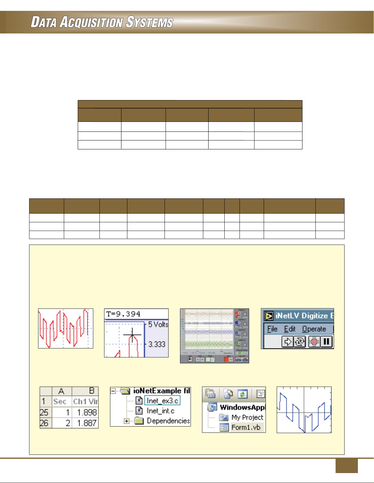
instruNet Software
instruNet includes software to interrogate, test, configure, and do I/O with all network channels. This
includes an application program called "instruNet World" and interfaces to Visual Basic, C, and C++.
instruNet software can configure all I/O channels, store your settings, view digitized data in real time,
stream data to disk, and scroll through your waveform post-acquisition. instruNet software runs on
Windows computers.
instruNet World
Direct To Excel
instruNet World Plus (iW+)
C/C++
DASYLab
Visual BASIC
LabView
instruNet Scope
5
Page 6
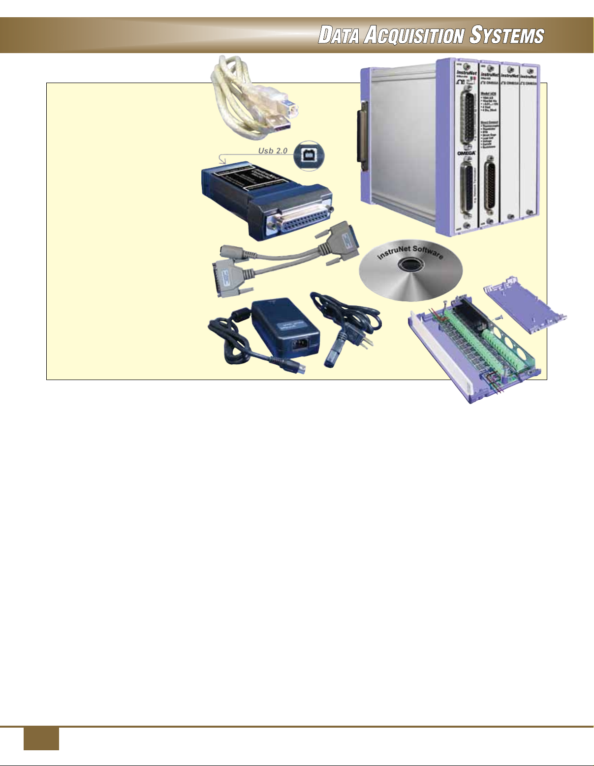
The iNET-555 Starter System,
shown to the right, provides the
following:
• USB 2.0 High Speed
Data Acquisition Hardware for
Windows ≥ XP SP2, Vista
7 or 8 (XP/VS/7/8)
• instruNet Software
• 16se/8di Voltage Inputs,
16-bit A/D
• 2x Precision Voltage Out
(±10V, 14 bit)
• 2x Voltage Outputs (0..+10V, 8 bit)
• 4x Universal Digital I/O (10V, 30V)
• Connect Directly to Sensors:
Voltage, Thermocouple,
Thermistor, RTD, Load Cell, Strain
Gage, Potentiometer, Current,
Resistance.
• Easily expand via 2 free slots in
4 slot iNET-400 Card Cage
• The iNET-555 Includes the
Following Products: iNET-240,
iNET-430, iNET-510, iNET-400,
iNET-410, iNET-312-8.
SPECIFICATIONS
iNET-400
No. of Slots: Each iNET-400
supports up to four cards. Multiple
iNET-400’s can be bolted together
side-by-side to create an 8, 12, or
16 slot system
Material: Solid aluminum
construction
Dimensions:
15 D x 11 W x 14 cm H
(6 x 4.5 x 5.6")
Mounting: Place on desktop, affix
to DIN rail, 19" rack, or wall mount
ANALOG INPUTS
No. of Channels:
iNET-420: 20 single-ended
(SE)/10 differential (DI)
iNET-423: 6 differential (DI)
iNET-430: 16 single-ended (SE)/
8 differential (DI)
A/D Converter: 16-bit
(iNET-430 only)
Voltage: See voltage accuracy/
range charts (on next page)
Thermocouple: J/K/T/E/R/S/B/N/
C/G/D
Thermistor: 2252 Ω
(OMEGA 44000 Series)
RTD: 100 Ω, 500 Ω, 1 kΩ platinum
Load Cell: 10 kg, 25 kg, 100 kg,
250 kg, 1000 kg, 5000 kg
Strain: 350 Ω (1/4 bridge,
half bridge or full bridge), 1 kΩ
(1/4 bridge)
Potentiometer: 10 kΩ, 50 kΩ
Current: ±80 uA, ±120 uA, ±500 uA,
±600 uA, ±800 uA, ±1.2 mA, ±2.5
mA, ±12 mA, ±24 mA,
0 to 24 mA
Resistance: 0 to 33 Ω, 0 to 100 Ω,
0 to 330 Ω, 0 to 1 kΩ, 0 to 3300 Ω,
0 to 10 kΩ
Common Mode Voltage: ±10 Vdc
(iNET-420 and iNET-430), ±5 Vdc
(iNET-423)
Crosstalk: < -80 dB typical
Input Impedance: 100 MΩ
iNET-430 PRECISION ANALOG
VOLTAGE OUTPUTS
No. of Channels: 2
Resolution: 14-bit
Range: ±10.1V
Output Current Drive: ±4 mA
iNET-430 ANALOG
VOLTAGE OUTPUTS
No. of Channels: 2
Resolution: 8-bit
Range: 0 to 10.1V
Output Current Drive: ±4 mA
DIGITAL I/O
(iNET-420/423/430)
No. of Channels: 4 universal digital
I/O (20 mA sink, -10 to 30V)
Working Voltage: -10 to 30 Vdc
“0” Input Voltage: -10 to 0.65V
“0” Input Current:
Amps = (4.5V – Vin)/3900
“1” Input Voltage: 2.1 to 30 Vdc
“1” Input Current: <1.4 mA
“0” Output Voltage:
<0.8V @ < 5 mA; < 2V @ <20 mA
“1” Output Voltage: 3.9 to 4.5V
“1” Output Current:
See "1" input current
Pull-Up Resistor: 3.9 kΩ±10%
Schmitt Trigger Input: Ye s
ENVIRONMENTAL
Operating Environment:
1 to 45°C (34 to 113°F), <90% RH
Storage Temperature: -20 to 70°C
(-4 to 158°F)
POWER
Required: +5 Vdc, ±12 Vdc required
(supplied by iNET-312-8)
User Available: 3.3 Vdc, 5 Vdc, ±12
Vdc
6
Page 7
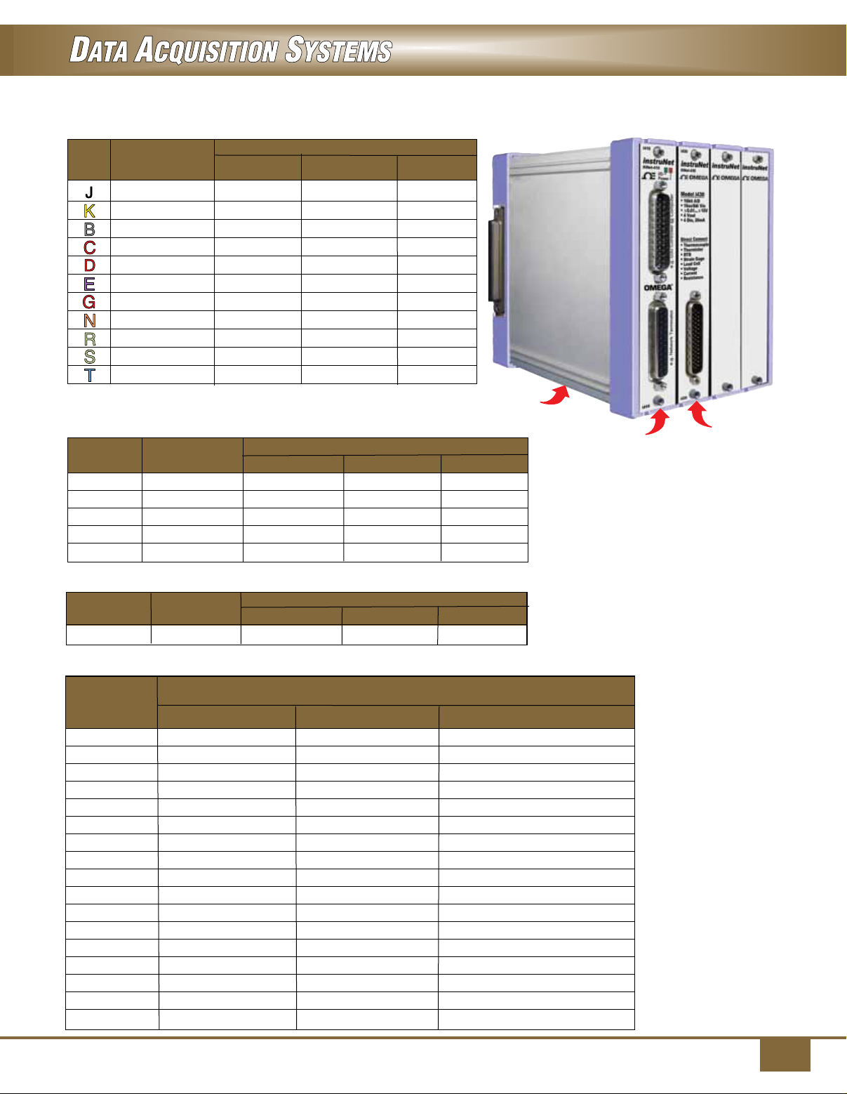
Thermocouple Range/Accuracy
T/C Range iNET-420 iNET-423 iNET-430
0 to750°C ±1.2°C ±1°C ±1°C
Accuracy
-200 to 1250°C ±1.4°C ±1.4°C ±1.2°C
250 to 1540°C ±3.8°C ±4.3°C ±3.7°C
0 to 2190°C ±2.6°C ±2.9°C ±2.6°C
0 to 1540°C ±2.6°C ±2.9°C ±2.6°C
-200 to 990°C ±1°C ±1.2°C ±1°C
0 to 2300°C ±5.4°C ±6.2°C ±5.3°C
-200 to 1140°C ±1.7°C ±2.2°C ±1.7°C
-40 to 1500°C ±2.9°C ±3.6°C ±2.9°C
-40 to 1500°C ±2.6°C ±2.9°C ±2.5°C
-200 to 400°C ±1.2°C ±1.4°C ±1.2°C
iNET-400
card cage
RTD (Requires OMEGA 10 kΩ shunt resistor iNET-R-10K)
Resistance
100 Ω
RTD
Range
iNET-420 iNET-423 iNET-430
-200 to -100°C ±3.1°C ±1.4°C ±1.3°C
Accuracy
100 Ω -100 to 300°C ±0.79°C ±0.79°C ±0.7°C
100 Ω 300 to 850°C ±5.4°C ±5.4°C ±2.6°C
500 Ω -100 to 300°C ±1.4°C ±1.4°C ±0.84°C
1,000 Ω -100 to 300°C ±0.44°C ±0.44°C ±0.8°C
iNET-410
Shown smaller than
actual size.
iNET-430
Thermistor (Requires OMEGA 10 kΩ shunt resistor iNET-R-10K)
Thermistor
Resistance
2252 Ω
Range
iNET-420 iNET-423 iNET-430
0 to 100°C ±0.27°C ±0.47°C ±0.47°C
Accuracy
Voltage Range/Accuracy
Voltage
Range 1
± 10V
iNET-420 iNET-423 iNET-430
±(0.017% + 671.µV) – ±(0.017% + 669.4µV)
(MAX Gain + Offset Error) with 1 ms Averaging
Absolute Accuracy
± 5V ±(0.017% + 364.3µV) ±(0.015% + 347.9µV) ±(0.010% + 332.7µV)
± 2.5V ±(0.017% + 290.7µV) ±(0.015% + 194.2µV) ±(0.010% + 178.9µV)
± 1.2V – ±(0.016% + 129.8µV) ±(0.010% + 141.9µV)
± 600 mV – ±(0.016% + 91.8µV) ±(0.010% + 94.6µV)
± 300 mV – ±(0.016% + 82.9µV) –
± 80 mV ±(0.015% + 10.3µV) ±(0.018% + 9.8µV) ±(0.015% + 10.1µV)
± 40 mV ±(0.015% + 8.0µV) ±(0.018% + 7.4µV) ±(0.015% + 7.7µV)
± 20 mV ±(0.015% + 7.4µV) ±(0.019% + 6.5µV) ±(0.015% + 7.2µV)
± 10 mV – ±(0.019% + 5.9µV) ±(0.015% + 6.5µV)
± 5 mV – ±(0.019% + 5.8µV) –
0 to 10V ±(0.017% + 364.8µV) – –
0 to 5V ±(0.017% + 290.7µV) ±(0.015% + 194.2µV) ±(0.010% + 178.9µV)
0 to 2.5V – ±(0.015% + 157.3µV) ±(0.010% + 141.9µV)
0 to 1.2V – – ±(0.010% + 94.6µV)
0 to 80 mV – ±(0.018% + 7.4µV) –
0 to 40mV – ±(0.018% + 6.9µV) –
7
Page 8
SM
OMEGACARESM extended warranty program is
available for models shown on this page. Ask
Extended Warranty
Program
your sales representative for full details when
placing an order. OMEGACARE
labor and equivalent loaners.
SM
covers parts,
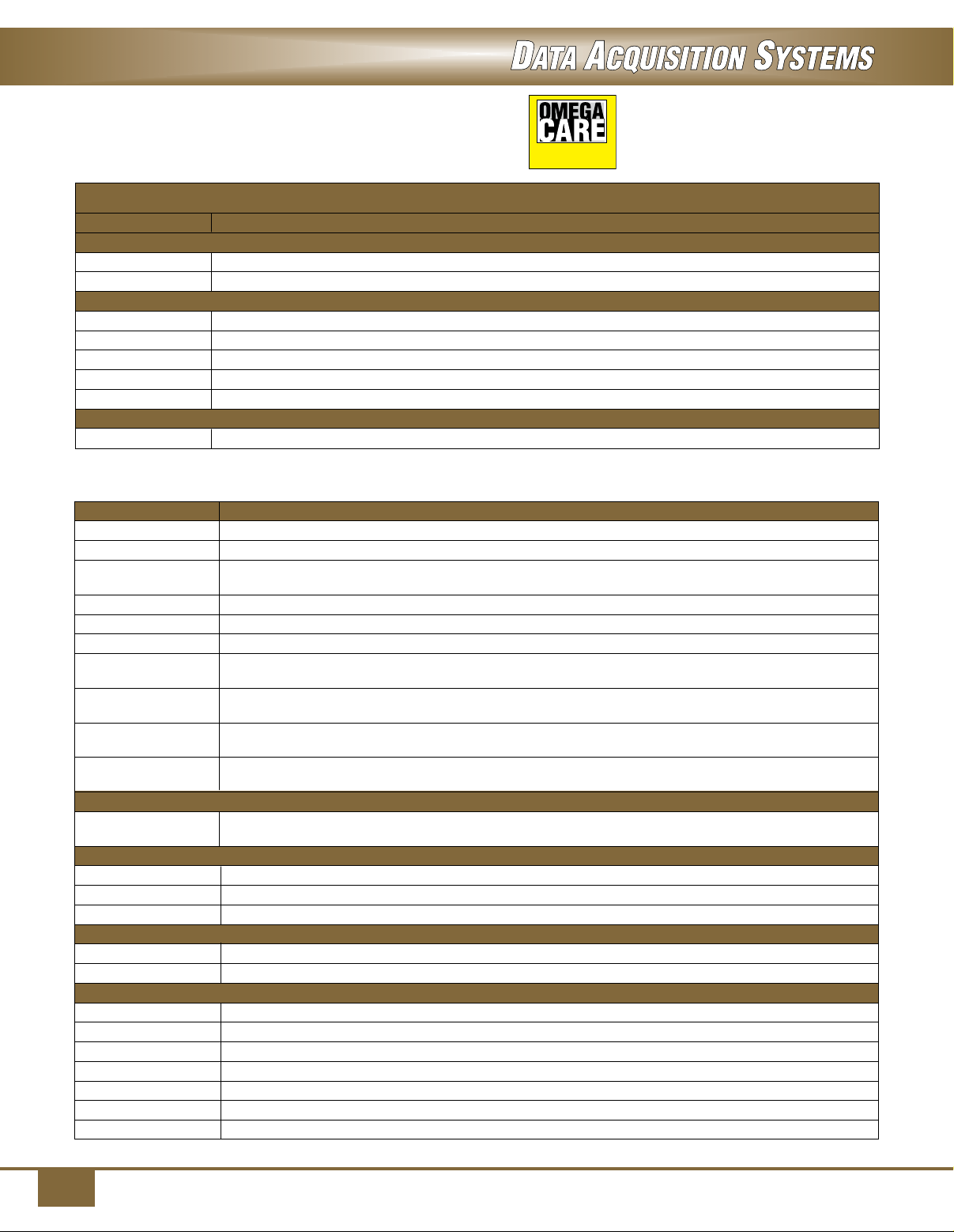
To Order
Model No. Description
Starter System
iNET-555 Starter system, USA plug
iNET-555-EU Starter system, European plug
iNET-400 Cards
iNET-410 Interface between iNET-240 contoller and iNET-400 card cage
iNET-420 20SE/10DI voltage input, multiplexer, 4 digital I/O
iNET-423 6DI voltage input, amplifier, filter, 4 digital I/O
iNET-430 16-bit A/D, 16SE/8DI voltage input, multiplexer, 4 voltage out, 4 DIO
iNET-460 28 digital I/O channels
iNET-400 Card Cage
iNET-400 Card cage for iNET-410/420/423/430/460 cards, 4 slots, expandable
Ordering Example: iNET-555 starter system including iNET-240, iNET-430, iNET-510, iNET-400, iNET-410 and iNET-312-8
and OCW-1 OMEGACARESM 1-year extended warranty adds 1-year to standard 1-year warranty.
Accessories
Model No. Description
iNET-510
iNET-511
iNET-512
iNET-HD44MF-3M Cable, Hd44m to Hd44f, 26 Awg, 3 m (10')
iNET-330 Optical isolator between iNET-240 controller and device
iNET-530 Wall and DIN rail mounting kit for one iNET-400 card cage
iNET-500-380HZ Analog low pass Butterworth filter daughter board for iNET-423 card, 380 Hz cut off frequency
iNET-500-1KHZ Analog low pass Butterworth filter daughter board for iNET-423 card, 1 kHz cut off frequency
iNET-500-3300HZ Analog low pass Butterworth filter daughter board for iNET-423 card, 3300 Hz cut off frequency
iNET-500-10KHZ Analog low pass Butterworth filter daughter board for iNET-423 card, 10 kHz cut off frequency
InstruNet Controller
iNET-240 USB instruNet controller for Windows ≥ XP SP2, comes complete with 3 m (10') USB cable, instruNet
Power Supplies
iNET-312-8 Power supply, USA Plug, 110/220 Vac, (includes iNET-300 power adaptor)
iNET-312-8EU Power supply, European plug, 110/220 Vac, (includes iNET-300 power adaptor)
iNET-300 Power adaptor
Software
iNET-iWPLUS instruNet World Plus software (iW+)
iNET-380 LabVIEW drivers (LabVIEW versions ≥4 currently supported on Windows ≥XP)
Shunt Resistors
iNET-R-33 33 Ω, 8-pack, 0.05%, 5 ppm/°C drift
iNET-R-120 120 Ω, 8-pack, 0.05%, 5 ppm/°C drift
iNET-R-350 350 Ω, 8-pack, 0.05%, 5 ppm/°C drift
iNET-R-1K 1000 Ω, 8-pack, 0.05%, 5 ppm/°C drift
iNET-R-3300 3300 Ω, 8-pack, 0.05%, 5 ppm/°C drift
iNET-R-10K 10 kΩ, 8-pack, 0.05%, 5 ppm/°C drift
iNET-R-33K 33 kΩ, 8-pack, 0.05%, 5 ppm/°C drift
Ordering Example: iNET-240, USB instruNet controller for Windows ≥ XP SP2.
Wiring box with screw terminals
Wiring box with BNC connectors
Strain gage/sensor wiring box with screw terminals (not for thermocouples - use iNET-510 for
thermocouple measurement)
(package of 2)
(package of 2)
(package of 2)
(package of 2)
network terminator and instruNet World software on CD (requires iNET-312-8 power supply).
8
 Loading...