

Page 1
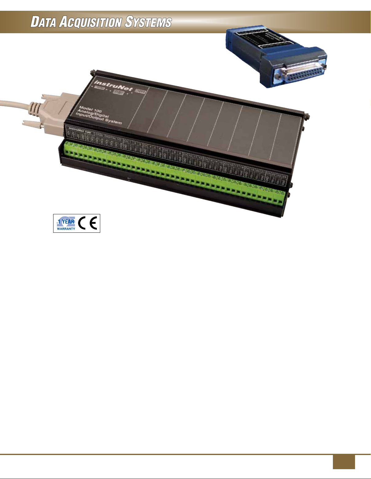
instruNET Series Direct Sensor to Data Acquisition
iNET-240 USB 2.0 controller,
shown larger than actual size.
iNet-100 Series
U High-Accuracy Data
Acquisition for Windows
Computers
U 16 Single-Ended/8 Differential
14-Bit Analog Inputs, 8 Analog
Outputs, and 8 Digital I/O
U iNET-240 USB 2.0 Controller
U Direct Connection to RTD,
Thermocouple, Voltage,
Current, Accelerometer,
Potentiometer, Load Cell,
Thermistor, Bridge, and
Strain Gage Sensors
U Each Channel Has
Independently Programmable
Analog and Digital Filters,
Integration Time, Voltage
Range, and Sample Rate
U 166 KS/s Throughput
to RAM or Disk
U Includes Strip Chart Software
and Drivers for C, Visual Basic.
Net, and TestPoint
U Optional LabVIEW
Drivers are Available
U Optional DASYLab Software
Includes iNET Drivers for
Easy-to-Use, Icon-Based
Programming
instruNet provides tens of microvolts
of absolute accuracy instead of
tens of millivolts, at the same cost
and at the same throughput rates
as typical general purpose data
acquisition boards. It does this with
a completely different topology in
which the analog electronics are
close to the sensor in electrically
quiet boxes outside the PC, and
noisy digital electronics are left
inside. The external boxes contain
signal conditioning amplifiers for
each channel and can attach
directly to sensors such as
thermocouples, thermistors, RTDs,
strain gages, load cells, resistance
sources, current sources, and
voltage sources. The box returns
engineering units to the PC
(e.g., °C, volts, amps).
At the heart of the real-time system
is a PCI card (WIN XP/VISTA
(32-bit)/7 (32-bit), PC-card (WIN XP/
VISTA (32-bit)/7 (32-bit) or USB 2.0
(WIN XP SP2/VISTA 32-bit
or 64-bit/7 32-bit or 64-bit) controller
that attaches to a Windows
computer. Each controller contains
a 32-bit microprocessor with 256
KB of RAM that manages the
external “network” of devices. All
real-time tasks are off-loaded to this
processor so that the host computer
is not burdened with real-time
issues. Each instruNet iNET-100
box provides 16 single-ended/8
differential analog inputs, 8 analog
outputs, and 8 digital I/O lines.
iNET-100 A/D box, shown
smaller than actual size.
The iNET-100 includes 44 screw
terminals. The iNET-100B version
adds 16 BNCs for analog inputs.
The controllers themselves have
10 counter/timer channels, each
of which can function as a digital
input bit, a digital output bit, a clock
output channel, a pulse counter,
a frequency counter, a period
measurement input, or a quadrature
counter.
Distributed and Expandable
The instruNet system is ideally suited
for distributed measurement and
control systems. The network cable
can extend up to 304.8 m (1000').
Each controller card in the PC can
connect to up to 8 instruNet boxes
for a total of 128 analog inputs,
64 analog outputs, and 64 digital
I/O. For additional inputs, multiple
controller cards can be placed in one
computer, with the maximum number
of controller cards limited only by the
number of available slots.
Since each controller card has its
own microprocessor, multiple cards
do not place any additional burden on
the computer. It should be noted that
multiple instruNet boxes on a single
network may degrade the maximum
system throughput of 166 KS/s.
1
Page 2
Material A
T
1
Material B
T
2
Copper
Copper
Readout
R
T
Copper
Copper Leads
Reference
Junction
Copper Leads
Readout
a (+ )
TR C
Cu
Potentiometer
b (-)
Cu
Coppe r
Coppe r
Measurin g
n
INSTRUNET SERIES DIRECT SENSOR TO DATA ACQUISITION
Thermocouple RTD Thermistor Strain Gage Voltage Current Resistance
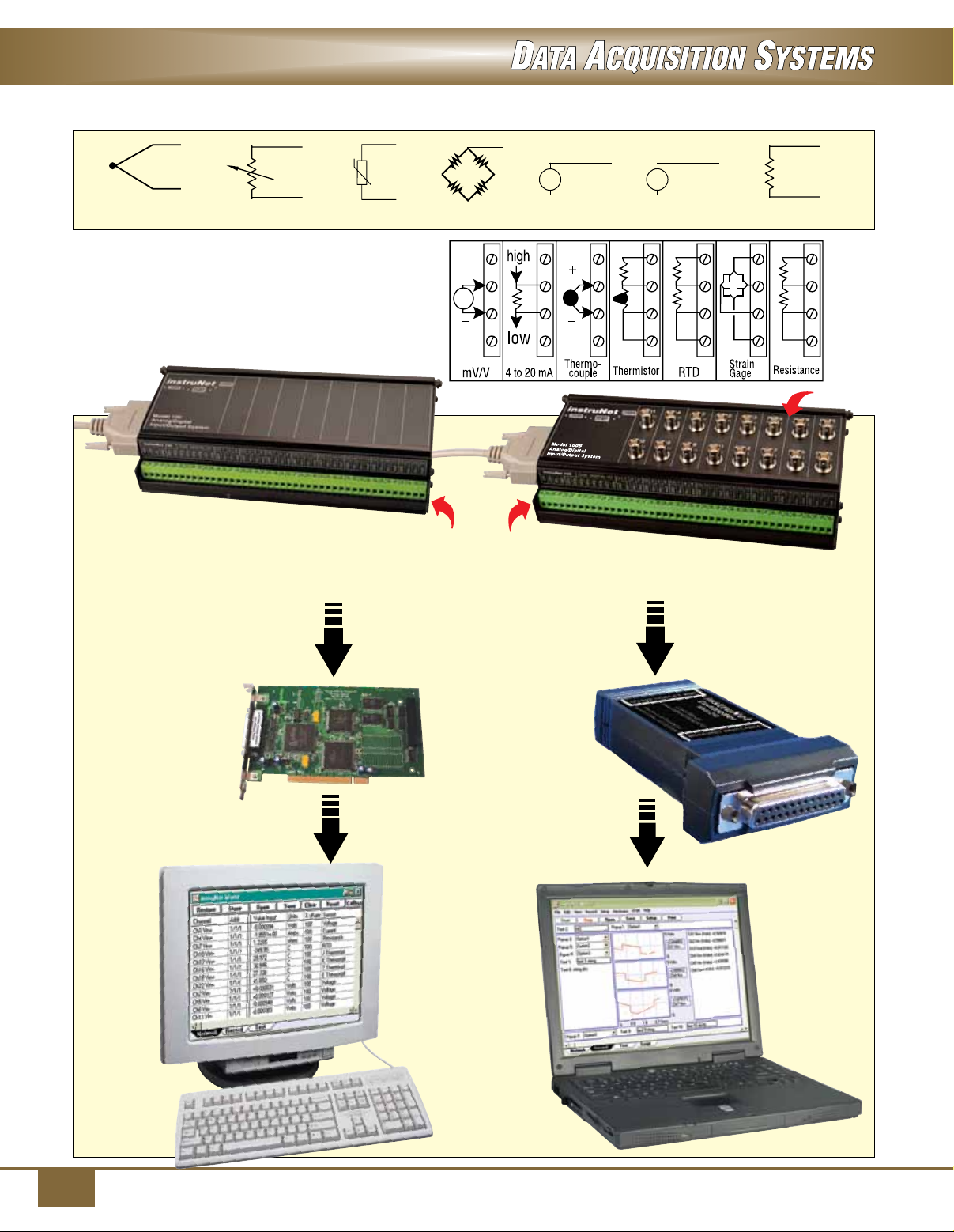
iNET-100 hook-up diagram.
iNET-100, /iNet-100HC*, up to 16
analog inputs, 8 analog outputs,
8 digital I/O.
*15 mA excitation current per channel.
V
Screw
Terminals
iNET-100B, up to 16 analog inputs with
BNC connectors, 8 analog outputs,
8 digital I/O.
Daisy chain multiple iNet-100
units for up to 128 analog outputs.
i
BNC
Connectors
card with PC interface
for Windows based PCs.
instruNET controller
iNET-200,
USB 2,0 controller
iNET-240,
for laptop or
desktop PCs.
2
Page 3
Performance
The instruNet system supports the
digitizing of multiple channels at a
maximum aggregate sample rate
of 166 KS/s, where each channel
can be digitized at its own rate. This
maximum rate decreases when the
total cable length increases, optical
isolation is used, digital filtering
or plotting is enabled, more boxes
are added, more channels are
digitized, amplifier gain is increased,
or spooling to disk is added. Each
channel can be independently
digitally filtered with low-pass,
high-pass, band-stop and and-pass
filters; the filter specification for each
channel is independently set in
software. Each channel provides
a programmable analog low-pass
filter with programmable A/D
measurement integration time.
The network can be hundreds of
feet long and can support multiple
hardware devices connected in
a daisy-chain configuration. The
start of digitizing can be triggered
from any channel. There are
no jumpers or pots; the system
automatically self-calibrates on
power-up. Because instruNet is
modular, it can easily be expanded
as needs evolve. One can easily
move the system hardware from one
computer family to another, since
the various controllers are
functionally identical.
High-Current Version (HC)
The iNET-100HC is similar to the
iNET-100, yet the voltage output
channels have a higher drive
capability, providing up to 15 mA of
current to capacitive loads as high
as 0.01 µF. The iNET-100 and
iNET-100B devices support only
4 mA/0.001 µF voltage output drive.
The iNET-100HC is recommended
for use with sensors such as strain
gages, RTDs, and thermistors,
since these sensors may exceed
the current or capacitive drive limits
of the iNET-100 or iNET-100B. The
iNET-100HC, furthermore, provides
greater compatibility with sensors
that have capacitive loading on
the excitation lines, therefore it
is recommended for all sensors
requiring excitation, including
RTDs and thermistors. Since the
HC version has a greater power
demand, an external power supply
must be used. The iNET-312-8
can be used for three additional
iNET-100HC boxes.
Software
“instruNet World” is a FREE
application program that manages,
monitors, and operates the
instruNet system. It digitizes long
continuous waveforms, spools them
to disk,views incoming waveforms
in real time, and then allows
post-acquisition viewing, much
like an oscilloscope or strip chart
recorder. instruNet World provides
a spreadsheet-like environment in
which one can set and view channel
parameters such as sensor type,
integration time, analog filter, and
digital filter. Each channel has its
own row in the spreadsheet, with
the various options in the columns.
instruNet is also compatible with
a variety of off-the-shelf software
products, including TestPoint,
Microsoft Excel 8 for Windows, and
DASYLab. For users writing their
own programs, instruNet includes
drivers callable from Visual Studio.
Net Basic or C. The driver includes
a main routine, called “iNet( )”, that
reads or writes any of the options
or channels on the system. Optional
drivers are also available for
LabVIEW software.
instruNet World Plus (for Windows
XP SP2/VISTA/7) software adds
valuable features to the standard
instruNet World software included
with instruNet hardware. It enables
the user to digitize, plot, control,
analyze, and save to disk A/D, D/A,
and digital I/O data from instruNet
hardware. In addition, it enables
one to define a personal instrument
front panel with buttons, pop-up
menus, edit fields, dynamic text,
text editor regions, and waveform
graphs. instruNet World Plus is
programmed with a simple script
language that can define tasks such
as control loops. For example, one
can type “Dac1 = OnOff (Ain1, 3)” to
define D/A #1 as a function of A/D
#1. Below is a list of the additional
features available only in instruNet
World Plus:
Generate Analog and Digital
Output Waveforms
Define an analog or digital output
channel mathematically (e.g., sine
wave, square wave, pulse train)
that updates in real time (e.g., every
100 ms).
Run Feedback/Control Loops
Define an analog or digital output
channel as a real-time function of
analog and/or digital input channels
(e.g. PID control, on/off control).
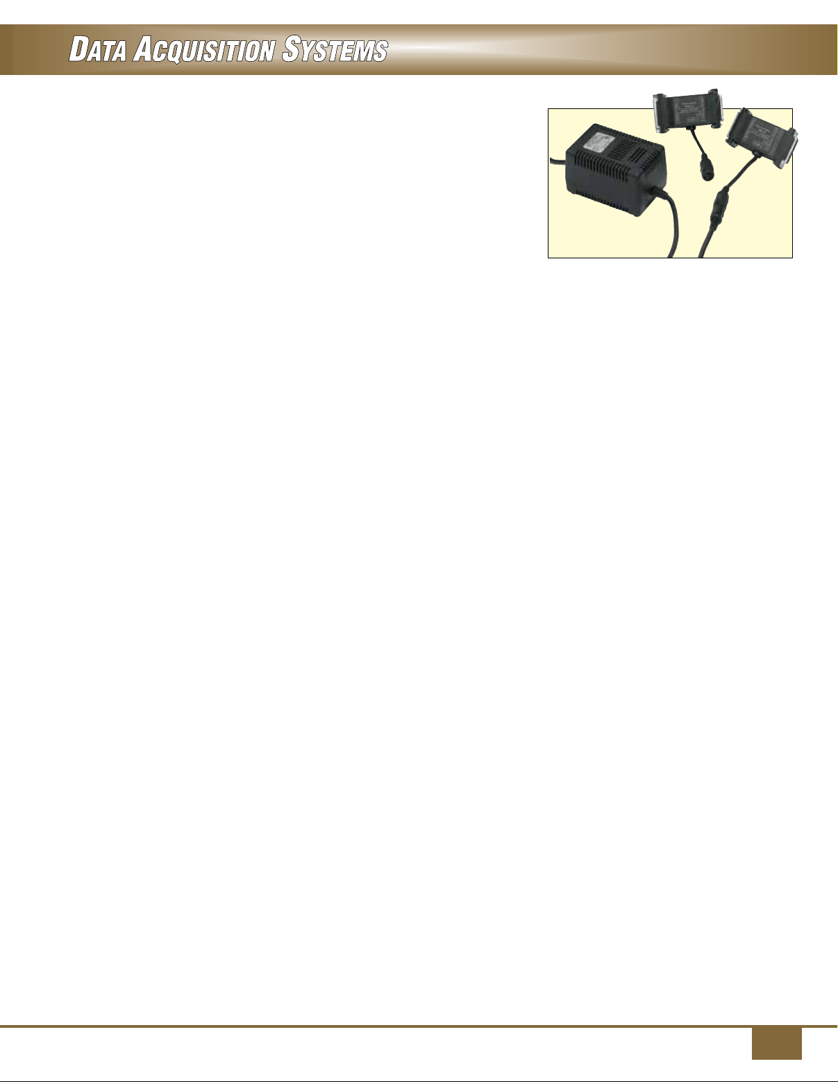
iNET-300
power adaptor
and iNET-330 isolator,
shown with iNET-312-8
power supply.
All shown
smaller than
actual size.
Create a Custom Instrument
Create buttons, pop-up menus, edit
fields, dynamic text fields, text edit
regions, and pages to build a custom
application program.
Powerful Script
Programming Language
instruNet World Plus is programmed
with a simple BASIC-like script
language that provides feedback/
control, waveform generation, math,
file, hardware, and user-interface
functions.
instruNet World Plus also Includes
Digitize Direct to Excel Software
InstruNet World Plus includes the
Digitize Direct to Excel program,
which populates an Excel (Version ≥
8.0, Office ≥ 97) spreadsheet in real
time while digitizing.
Power Requirements
Since instruNet is powered directly
from the iNET-200 controller card,
it is possible to exceed the power
capacity of the controller card if
multiple instruNet iNET-100 boxes are
attached to a network. For systems
using the iNET-200 PCI bus controller
card with more than 2 iNET-100/100B
boxes or 1 iNET-100HC instruNet
box on a network, external power is
required. Two power adaptors are
available: the iNET-300 power adaptor
and the iNET-330 adapter/isolator.
Both devices connect in line with
the instruNet communications cable;
the iNET-300 provides power only,
while the iNET-330 provides power
and electrical isolation between the
iNET-100 boxes and the computer.
Isolation helps eliminate ground loop
problems. Both the iNET-300 and
iNET-330 require either the iNET-3128 (USA plug) or iNET-312-8EU (Euro
plug) power supply. The iNET-312-8
can power
4 additional iNET-100/100B or
3 additional iNET-100HC. The
iNET-230 controller card does not
provide power; the iNET-312-8 or
iNET-312-8EU power; supply must be
used with this card.
3
Page 4
instruNET Series Direct
Sensor to Data Acquisition
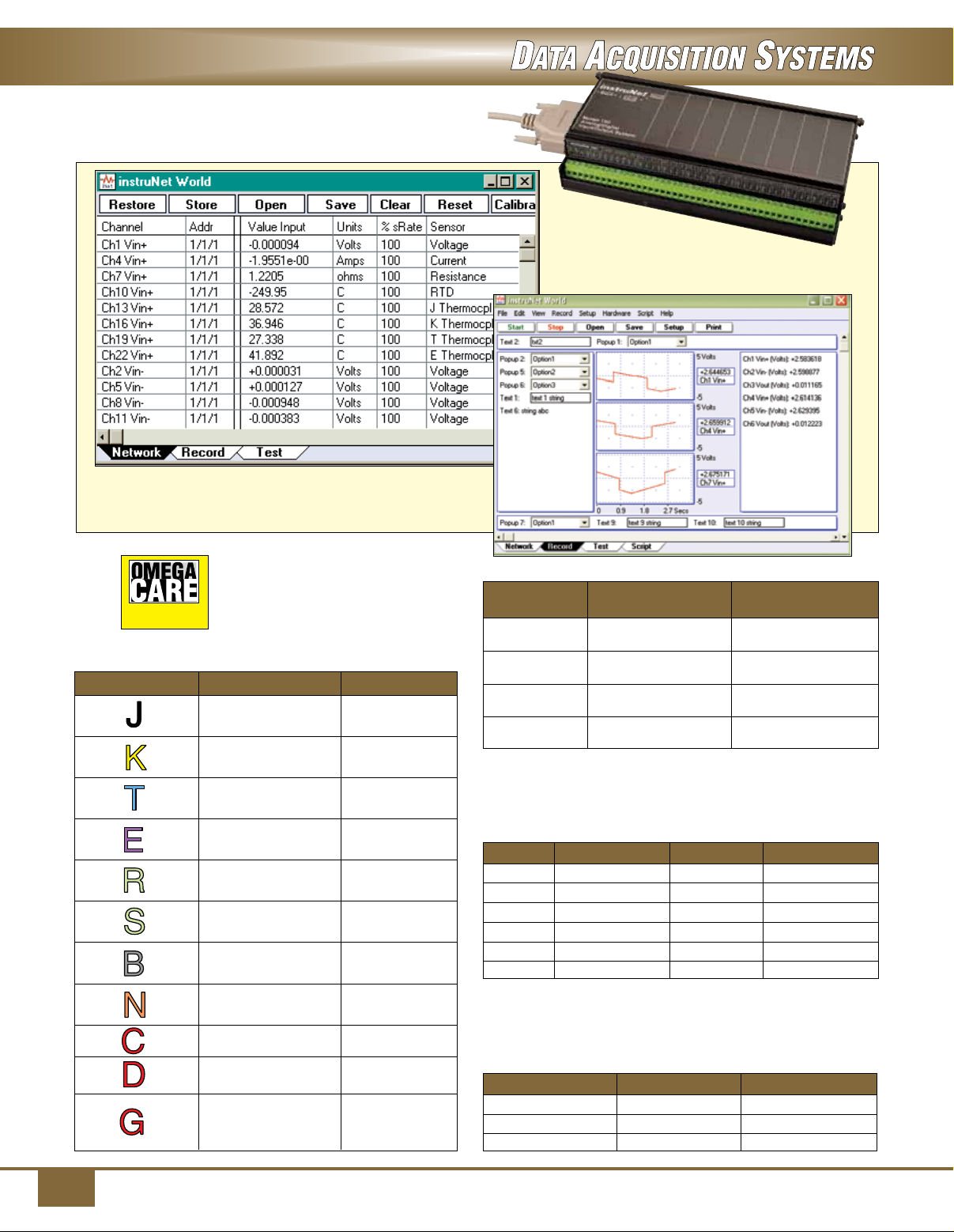
instruNet World Data Acquisition Software
(included with the instruNet System).
SM
OMEGACARESM extended warranty
program is available for models shown on
this page. Ask your sales respresentative
Extended Warranty
Program
Thermocouple Ranges/Accuracy
Thermocouple Range Accuracy
-210 to -100°C ±0.8°C
-100 to 1200°C ±0.5°C
-200 to -50°C ±0.8°C
-50 to 1372°C ±0.6°C
-200 to -100°C ±0.8°C
-100 to 400°C ±0.5°C
-200 to -60°C ±0.7°C
-60 to 1000°C ±0.5°C
-50 to 70°C ±3.5°C
70 to 1768°C ±2.0°C
-50 to 150°C ±2.8°C
150 to 1768°C ±1.8°C
250 to 600°C ±3.8°C
600 to 1820°C ±2.0°C
-200 to -110°C ±1.3°C
-110 to 1300°C ±0.8°C
0 to 2315°C ±2.4°C
0 to 2315°C ±2.2°C
0 to 100°C ±16.0°C
100 to 300°C ±3.4°C
300 to 2315°C ±1.8°C
for full details when placing an order.
OMEGACARESM covers parts, labor and
equivalent loaners.
instruNet World Plus Data Acquisition Software
below (not included—need to puchase software
license), iNET-iWPLUS.
Voltage Range/Accuracy
Voltage Integration
Range (Seconds) Accuracy
±5V 1 ms ±700 µV
none ±1500 µV
±0.6V 1 ms ±75 µV
none ±150 µV
±80 mV
none ±45 µV
±10 mV
none ±30 µV
±80 mV and ±10 mV are nominal ranges. Actual ranges may be as low
*
as ±78 mV and ±8 mV, respectively
* 1 ms ±15 µV
* 1 ms ±10 µV
RTD Accuracy Ranges
RTDs with α = 0.00385 and 0.00392 supported. One
user-supplied shunt resistor per RTD channel is required.
RTD Range Shunt Accuracy
100 Ω 0 to 200°C 1 kΩ ±0.37°C
100 Ω 0 to 850°C 2 kΩ ±1.0°C
500 Ω 0 to 200°C 4.7 kΩ ±0.38°C
500 Ω 0 to 850°C 10 kΩ ±0.9°C
1000 Ω 0 to 200°C 10 kΩ ±0.36°C
1000 Ω 0 to 850°C 20 kΩ ±0.85°C
Thermistor Accuracy/Ranges
All OMEGA® 44000 Series thermistors supported. (Consult Sales
for other thermistors); one user-supplied shunt resistor per
thermistor channel is required.
Range Shunt Accuracy
-80 to 40°C 47 kΩ ±0.2°C
0 to 70°C 4.7 kΩ ±0.1°C
0 to 200°C 200 Ω ±0.4°C
4
Page 5
SPECIFICATIONS
Analog Inputs:
16 single-ended/8 differential
Resolution: 14-bit
System Throughput:
166K samples/s
A/D Conversion Time: 4 µs min
Signal-to-Noise Ratio: 78 dB
Linearity: Differential ±1.5 LSB;
integral ±2 LSB
Input Overvoltage Protection: ±15V
Input Impedance: >22 MΩ, 3pf
Common-Mode Voltage:
±5V min (CMR ±80 dB)
Gain and Offset Drift: ±5 ppm/°C
of 5V FSR; offset self-calibrated to 0
Analog Outputs: 8
Resolution: 8-bit
Output Range:
iNET-100/100B: ±5V @ 5 mA
iNET-100HC: ±5V @ 15 mA
Output Protection:
Short-to-ground continuous
Output Settling Time: 4 µs (to ±2 LSB,
±5V step)
Analog Output Accuracy: ±0.4%
Digital Coupling: ±20 mV
Gain and Offset Drift: ±10 ppm/°C
of 5V FSR and ±5 µV/°C offset drift
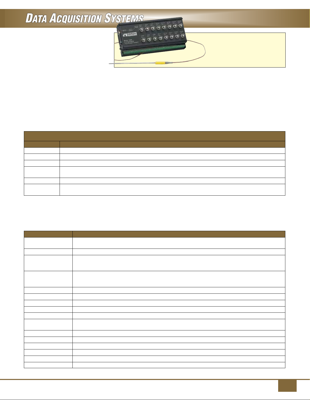
iNET-100B, shown smaller
than actual size with
KMTSS-125U-6 thermocouple
probe, sold separately.
Visit us online for more
thermocouple probes.
Digital I/O Number: 8 non-latching
inputs and 8 latching outputs at
8 bidirectional screw terminals
Input Levels:
V
= 3.2V min to 12V max
IH
V
= 1.0V max to -12V min
IL
I
= -200 µA, Vi = 3.2V
IH
I
= -0.5 mA max
IL
Output Levels:
V
= 2V min to 5V max
OH
I
= -0.5 mA max
OH
I
= 500 mA max, VO =1.7V
OL
I
= 50 mA max, VO = 0.7V
OL
To Order
Model No. Description
iNET-100 instruNet external A/D box with screw terminal connections
iNET-100B instruNet external A/D box with screw terminal and BNC connections
iNET-100HC Same as INET-100 with 15 mA excitation current per channel
iNET-240 USB 2.0 controller for Windows XP SP2//VISTA (32-bit of 64-bit)/7 (32-bit or 64-bit);
iNET-200 PCI-Bus controller card for Windows XP/VISTA (32-bit)/7 (32-bit) computers (controls up to 8 iNET-100s)
iNET-230
Comes complete with operator’s manual, instruNet World data acquisition software, driver software and network terminator.
The iNET-100/100B/100HC include a 3 m (10’) cable for connecting the iNET-100/100B/100HC to the controller�card or other iNET-100/100B/100HCs.
†
iNET-230 is not supported under Windows NT.
Ordering Examples: iNET-100 external A/D box, OCW-1, OMEGACARE
iNET-240, USB 2.0 controller and OCW-1, OMEGACARESM 1-year extended warranty for (adds 1 year to standard 1-year warranty)
iNET-100, external A/D box, and iNET-240 USB 2.0 controller
†
Accessories
Model No. Description
iNET-300
iNET-330
iNET-312-8 Power supply; 110/220 Vac, 5 V/2 A, ±12 V/0.8 A; USA plug used with iNET-300/330/230,
iNET-312-8EU Power supply; 110/220 Vac, 5 V/2 A, ±12 V/0.8 A; 2-prong Euro plug, used with
iNET-340 DIN rail mounting brackets for one iNET-100
iNET-CABLE-10FT instruNet cable, 3.0 m (10’) length
iNET-CABLE-25FT instruNet cable, 7.6 m (25’) length
iNET-CABLE-50FT instruNet cable, 15.2 m (50’) length
iNET-CABLE-100FT instruNet cable, 30.5 m (100’) length
iNET-iWPLUS instruNet World Plus software license for one controller card (includes CD and license
iNET-380
OMX-R250 Precision 250 Ω shunt resistor (1% tolerance)
OMX-R(*) Precision shunt resistor, specify resistance code (200, 2K, 10K or 20K)
OMX-R1K Precision shunt resistor, 1 kΩ
OMX-R4.7K Precision shunt resistor, 4.7 kΩ
OMX-R47K Precision shunt resistor, 47 kΩ
Note: Insert resistance code in ohms. Available resistance codes are 200, 2K, 10K or 20K.
*
Ordering Example: iNET-312-8, power supply, 110/220 Vac.
requires inet-312-8 power supply
PC-Card controller, type II for Windows XP/VISTA (32-bit)/7 (32-bit)
(does not provide power, requires iNET-312-8 power supply)
SM
1-year extended warranty (adds 1-year to standard 1-year warranty),
Power adaptor, required if using more than 2 iNET-100/100B boxes or one iNET-100HC box
with the iNET-200 PCI controller card; the iNET-230 PC card controller provides its own power adaptor
Optical isolator, isolates signal and power lines (replaces iNET-300, requires iNET-312-8 power supply)
iNET-300 included (powers 3 additional iNET-100HC or 4 additional iNET-100/100B);
includes iNET-300 power adaptor
iNET-300/330/230 (powers 3 additional iNET-100HC or 4 additional iNET-100/100B);
includes iNET-3000 power adaptor
certificate for Windows XP SP2//VISTA/7)
LabVIEW drivers (LabVIEW versions 4 to 6 currently supported on
Windows XP SP2//VISTA/7)
5
 Loading...