

Page 1

iMonnit User
Guide
Page 2

Table of Contents
I. ABOUT THE WIRELESS CONTROL UNIT 1
iMONNIT BASIC 1
iMONNIT PREMIERE 1
iMONNIT SUBSCRIPTIONS - FEATURE COMPARISON 2
DOWNLOADING THE iMONNIT APP 3
iMONNIT SECURITY
4
II. REGISTRATION
LOGGING INTO THE ONLINE SYSTEM
REGISTERING A DEVICE
III. OVERVIEW PAGE
MAIN NAVIGATION MENU
IV. SENSOR OVERVIEW
MENU SYSTEM
V. GATEWAY OVERVIEW
HOW GATEWAYS WORK
GATEWAY SETTINGS
VI. REPORTS OVERVIEW
ADDING A REPORT
VII. EVENTS OVERVIEW
CREATING AN EVENT
VIII. SENSOR MAPS OVERVIEW
CREATING A SENSOR MAP
IX. ACCOUNT MENU OVERVIEW
ACCOUNT SETTINGS
USER LIST
NETWORK MANAGEMENT
WEBHOOK
5
6
6
7
7
8
8
15
15
16
23
23
24
25
28
28
30
31
36
37
38
SUPPORT
WARRANTY INFORMATION
40
40
PAGE II
Page 3

I. ABOUT iMONNIT
iMonnit® is a cloud based mobile internet platform and central hub for managing Monnit® and
ALTA® products. All data is secured on dedicated servers operating Microsoft SQL Server.
This online user interface is where all your device settings can be arranged, supervised, and
modied to reect your unique environment. You can access iMonnit on any internet browser
simply by typing www.imonnit.com into the address bar. In addition, you can also download
the iMonnit App from to your smartphone or tablet. Start with the basic version or upgrade to
iMonnit Premiere to enjoy the full features your Monnit experience can oer.
iMONNIT BASIC
iMonnit Basic is included for free with all wireless sensors, providing basic features for you to
congure and monitor your sensors online. These basic features only support one network
and one registered user on an account. More advanced settings, permissions, and actions
are available with an upgrade to iMonnit Premiere.
iMONNIT PREMIERE
iMonnit Premiere allows for enhanced functionality of your wireless sensors and includes an
advanced software feature set at a low annual cost. All of iMonnit’s advanced features are
available for conguration. You can have more sensors on your account, support multiple
users, and view oorplans for all your sensors.
System Requirements
• Ethernet gateways require existing Internet connection
• Wireless Sensor Adapter or USB Pro Gateways require Windows PC or 3rd party
IoT gateway
PAGE 1
Page 4
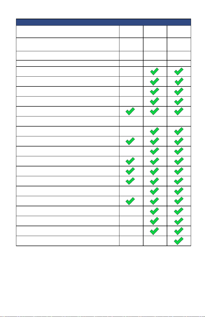
iMONNIT SUBSCRIPTIONS - FEATURE COMPARISON
FEATURE iMONNIT
Annual Price
Number of Sensors Supported Per Network
Sensor Heartbeat Under Two Hours
Allows Sensor heartbeats to be set under two hours.
Can View Maps
Allows access to map pages
Have Multiple Users
Allows account to have more than one user.
Have Multiple Networks
Allows account to have more than one network
Can Calibrate Sensors*
Allows access to calibrate sensors.
Select Old Data
Ability to select past data.
Sensor Advanced Conguration
Ability to Edit Advanced sensor congurations.
Multiple Wi-Fi Networks
Allows additional Wi-Fi networks to be congured on a Wi-Fi Sensor.
Webhook Authorization
Allows access to set up and use the Webhook
Voice Notication Conguration
Allow voice call as a notication alerting option.
Customize Text (SMS) Notications
Allow text as a notication alerting option.
Notication Text Override
Allow the extra elds to be used on a notication.
Advanced Notication Settings
Allow the extra elds to be used on a notication.
Conguration of System Actions
Allow the use of system actions on notications.
Enhanced Notications
Allow the creation and use of advanced notications.
Access to Scheduled Notications
Allows the creation and use of scheduled notications.
Full Use of REST API
Allows the use of the REST APIs
Does Not Require Internet Connection
No internet connection is required to operate.
*
Applies to certain types of sensors only.
** iMonnit Enterprise installation support available. Call for pricing.
*** Requires an internet connection.
BASIC
Online Sensor
Monitoring
FREE Starting at $39
500 6 to 999 6 to 999
90 days 365 days Congurable
iMONNIT
PREMIERE
Advanced
Online Sensor
Monitoring
iMONNIT
ENTERPRISE
Self Hosted
Enterprise
Software
Call For
Pricing**
PAGE 2
Page 5
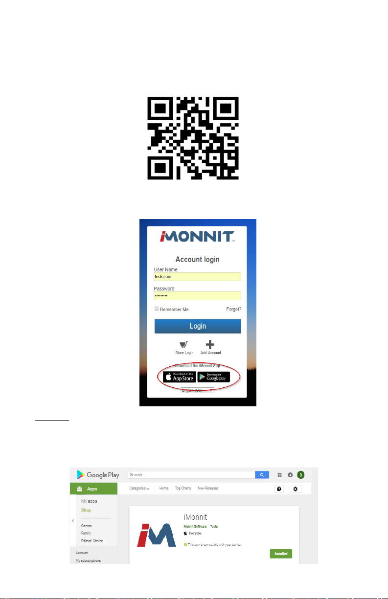
DOWNLOADING THE iMONNIT APP
The iMonnit app is available on both Google Play and the Apple App Store. Use the follow-
ing QR code to link directly to a page where links to download the mobile app will take you
directly to where you can install the program on your device.
Alternatively, you can go to the iMonnit site and select one of the direct links in the bottom
of the login box.
Android
Select the link to go to the Google Play store and download the “iMonnit: Mobile Software.”
Choose the Install button and the app will begin to download to your smartphone or tablet.
Note: The app requires Android 4.0 and up.
PAGE 3
Page 6
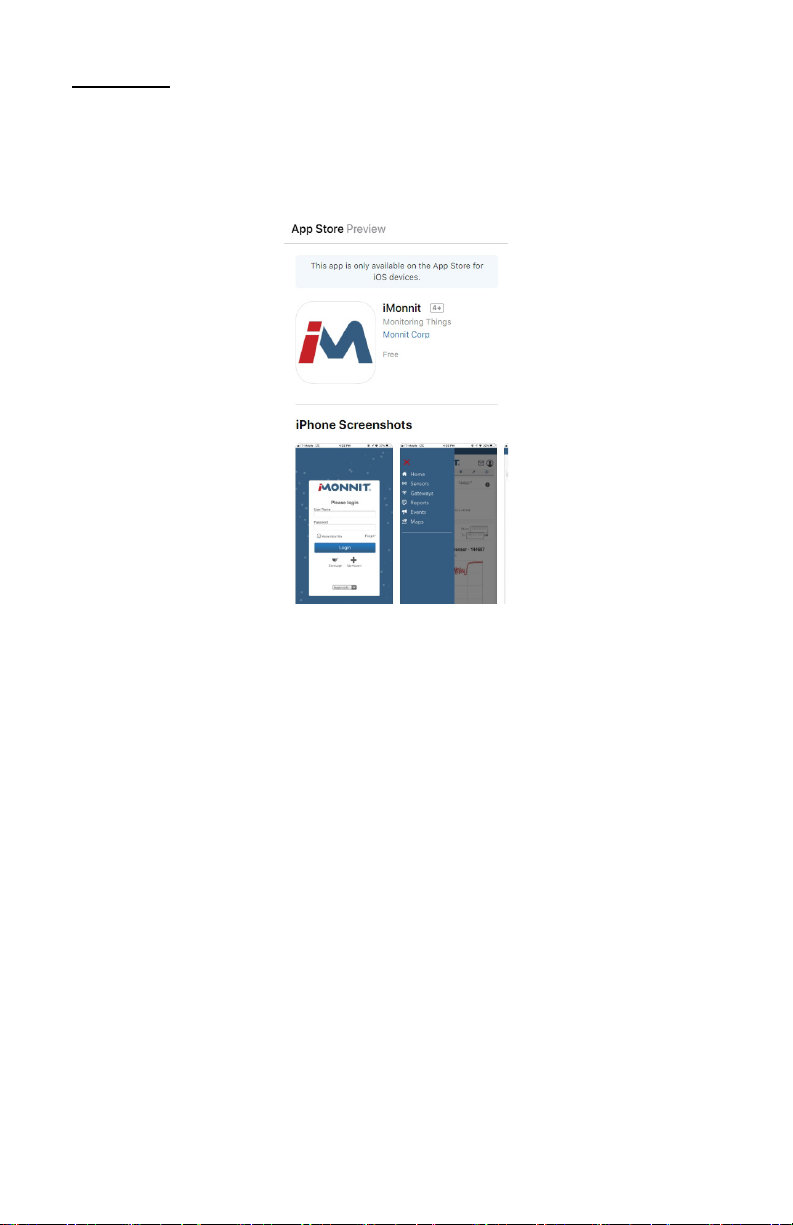
Apple (iOS)
Choose the link for the Apple (iOS) app to be taken to the App Store for Mac Devices. The
app works with iPhone, iPad, and iPod Touch and free to download. Select the app labeled
“iMonnit: Mobile Software.” Download the app and start registering your devices.
Note: The app is only available on the App Store for iOS devices and requires iOS 11.0 or
later.
iMONNIT SECURITY
Security is paramount for the iMonnit when it comes to managing your environment and
equipment. Great care and attention to detail has been taken to keep the exchange of data
secure on a gateway and in device communications.
iMonnit is the online software and central hub for conguring your device settings. All
data is secured on dedicated servers operating Microsoft SQL Server. Access is granted
through the iMonnit user interface, or an Application Programming Interface (API)
safeguarded by 256-bit Transport Layer Security (TLS 1.2) encryption. TLS is blanket of
protection to encrypt all data exchanged between iMonnit and you. The same encryption
is available to you whether you are a Basic user of Premiere user of iMonnit. You can rest
assured that your data is safe with iMonnit.
PAGE 4
Page 7
II. REGISTRATION
If this is your rst time using the iMonnit online portal, you will need to create a new
account. If you have already created an account, you can skip to the “Logging into the
Online System” section. The following instructions will guide you through creating the
account.
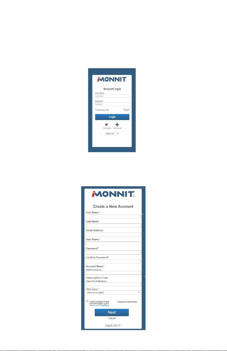
1. Open iMonnit in your mobile app or web browser.
2. Navigate your cursor down to the bottom of the login box and select “Add Account”.
3. Next you will be asked to enter your account information in the following elds:
Note: If this is a Free Trial, you may not have received a subscription code yet. Leave the box blank and proceed.
PAGE 5
Page 8
4. When completed, select the “Next” button.
5. This step will complete the user registration process and lead you into registering your
device. You will be able to log out and log back in with your credentials to complete the
setup at any time.
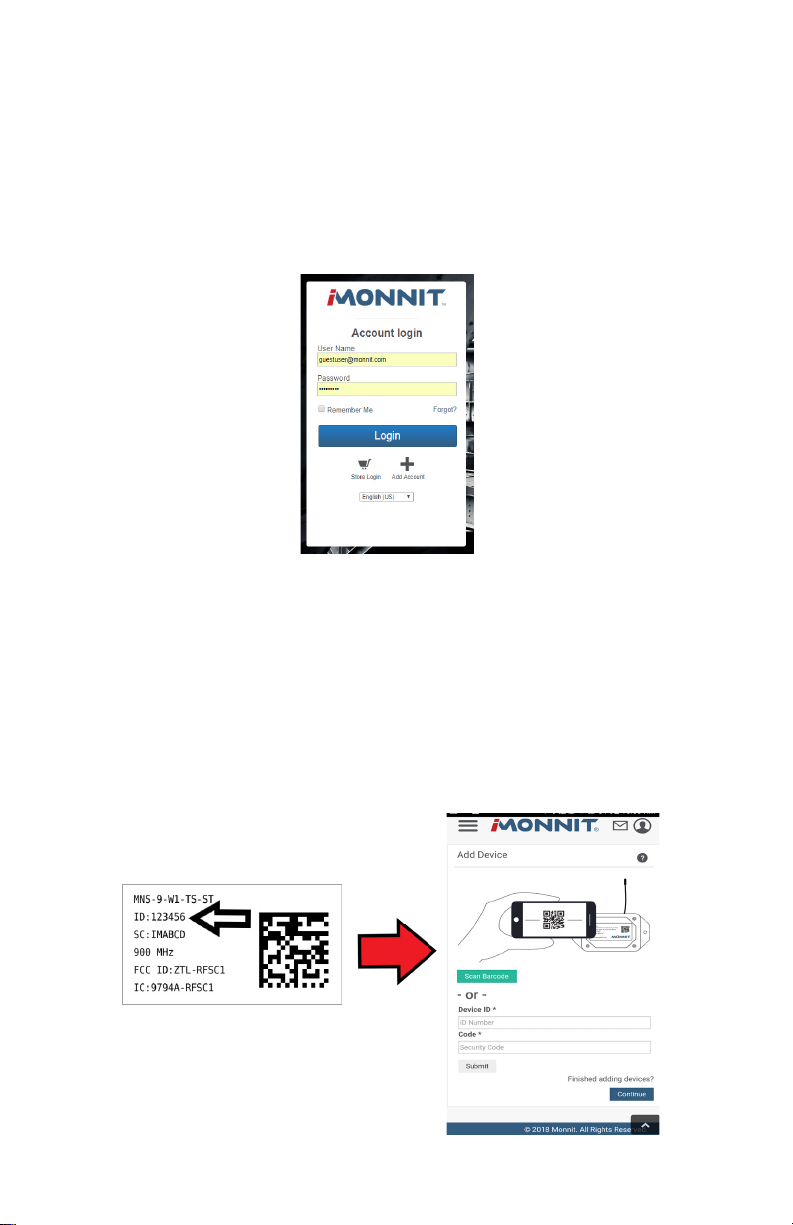
LOGGING INTO THE ONLINE SYSTEM
1. Open iMonnit in your mobile app or web browser.
2. Enter your user name and password.
3. Select the “Login” button.
REGISTERING A DEVICE
You will need to enter the Device ID and the Security Code from your devices in the
corresponding text boxes. Use the camera on your smartphone to scan the QR code on
your sensor and gateway. If you do not have a camera on your phone, or the system is not
accepting the QR code, you may enter the Device ID and Security Code manually.
• The Device ID is a unique number located on each device label.
• Next you’ll be asked to enter the Security Code (SC) on your device. A security
code will be all letters and must be entered in upper case, no numbers. It can also
be found on the barcode label of your gateway.
When completed, select the “Submit” button.
PAGE 6
Page 9
III. OVERVIEW PAGE
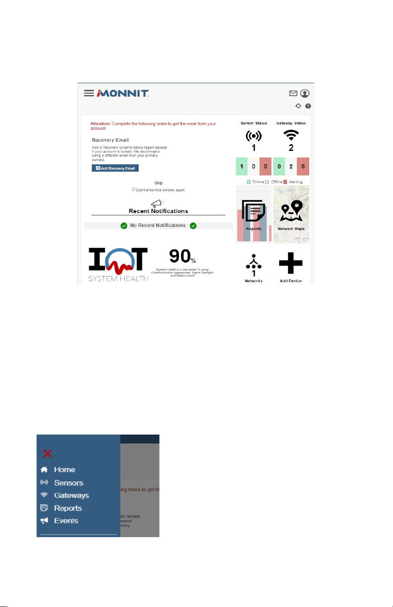
The overview page is the homepage for iMonnit. From here, you can view important noti-
cations and have a central dashboard from where you can drill down into more specic
information.
If there’s anything left to do on your account you’ll see an alert above your notications. You
have the option to skip the alert or check the box so the window does not display again.
If no notications have triggered recently, or you haven't set up your notication settings,
this portion of the dashboard will be blank. Below your recent notications is a percentage
denoting your overall system health.
Note: The System Health percentage is calculated using the average gathered from Communication
Assessment, Signal Strength, and Battery Level.
This will be your iMonnit homepage. Check it regularly to make sure your sensor(s) and
gateway(s) are functioning properly.
MAIN NAVIGATION MENU
The main navigation menu is the primary you will refer
to for information regarding your devices and settings.
It is dierent from the account menu which will be
covered later in this user guide. The sections of the
menu are:
• Home - This will take you back to the overview
page.
• Sensors - Takes you to the sensor page.
• Gateways - Takes you to the gateway page.
• Reports - Takes you to the reports page.
• Events - Takes you to the events page.
Each of these options are covered in their own user guide sections. Read on for more
information on these various pages.
PAGE 7
Page 10
IV. SENSOR OVERVIEW
Select Sensors from the main navigation menu to access the sensor overview page and
begin making adjustments to your sensors.
MENU SYSTEM
Details - Displays a graph of recent sensor data.
History - List of all past heartbeats and readings.
Events - List of all events attached to this sensor.
Settings - Editable levels for your sensor.
Calibrate - Reset readings for select sensors (Not available for all sensor types).
Scale - Change the scale of readings for your sensor (Not available for all sensor types).
Directly under the tab bar is an overview of your sensor. This allows you to see the signal
strength and the battery level of the selected sensor.
• indicates the sensor is checking in and within user dened safe parameters.
•
indicates the sensor has met or exceeded a user dened threshold or triggered event.
indicates that no sensor readings are being recorded, rendering the sensor inactive.
•
Details View
The Details View will be the rst page you see upon selecting which sensor you would like
to modify.
PAGE 8
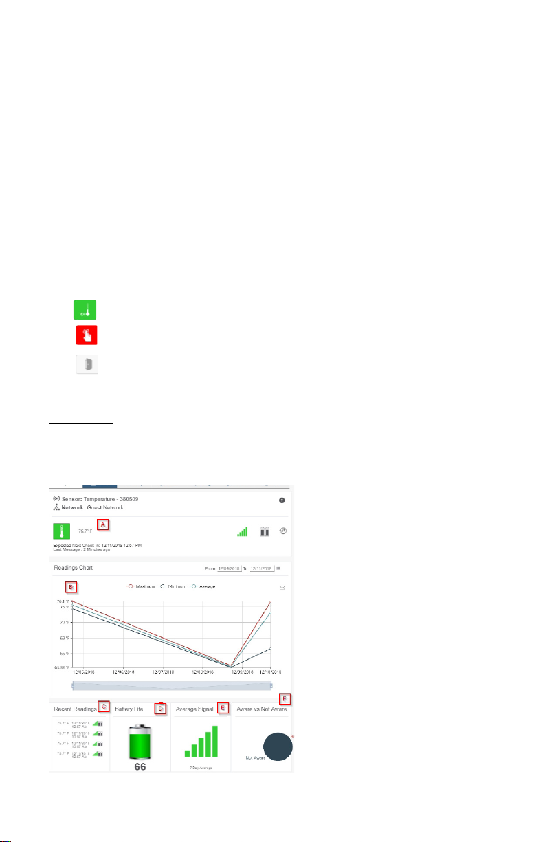
A. The sensor overview section
will be above every page. This will
consistently display the present
reading, signal strength, battery level,
and status.
B. This graph charts how the sensor
uctuates throughout a set date
range. To change the date range
displayed in the graph, navigate up to
the top of the Readings Chart section
on the right-hand corner to change
the from and/or to date.
C. The Recent Readings section
below the chart shows your most
recent data received by the sensor.
D. Battery Life displays the current
battery percentage remaining.
E. The Average Signal shows the
most common signal strength of your
sensor. Low signal strength could be
Page 11
a sign the placement of your sensor should be adjusted.
F. The pie chart in the Aware or Not Aware Section displays the percentage of aware states
your sensor has entered since activation.
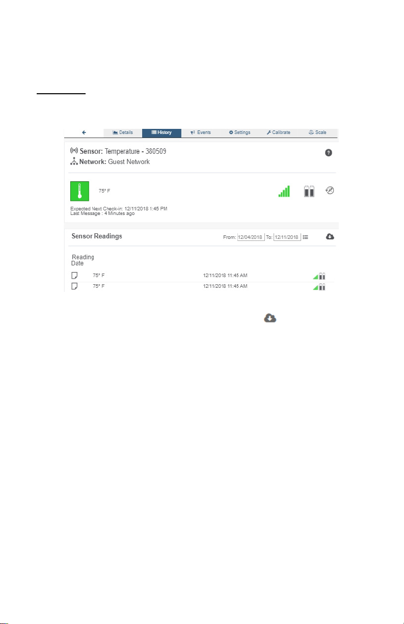
History View
Selecting the “History” tab within the tab bar allows you to view the sensor’s data history as
time stamped data.
• On the far right of the sensor history data is a cloud icon. Selecting this icon will
export an excel le for your sensor into your download folder.
Note: Make sure you have the date range for the data you need input in the “From” and “To” text boxes. This will be
the most recent week by default. Only the rst 2,500 entries in the selected date range will be exported.
The data le will have the following elds:
MessageID: Unique identier of the message in our database.
SensorID: If multiple sensors are exported you can distinguish which reading was from
which using this number even if the names for some reason are the same.
Sensor Name: The name you have given the sensor.
Date: The date the message was transmitted from the sensor.
Value: Data presented with transformations applied but without additional labels.
Formatted Value: Data transformed and presented as it is shown in the monitoring portal.
Battery: Estimated life remaining of the battery.
Raw Data: Raw data as it is stored from the sensor.
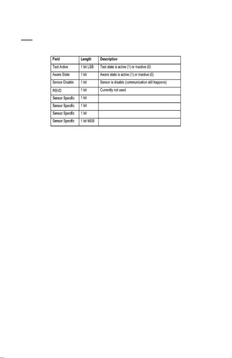
Sensor State: Binary eld represented as an integer containing information about the state
or the sensor when the message was transmitted. (See “Sensor State Explained” below).
Gateway ID: The Identier of the gateway that relayed the data from the sensor.
Alert Sent: Boolean indicating if this reading triggered a notication to be sent from the
system.
Signal Strength: Strength of communication signal between the sensor and the gateway,
shown as percentage value.
PAGE 9
Page 12
Voltage: Actual voltage measured at the sensor battery used to calculate battery percentage,
similar to Received Signal you can use one or the other or both if they help you.
State
The integer presented here is generated from a single byte of stored data. A
byte consists of 8 bits of data that we read as Boolean (True (1)/False (0)) elds.
Using a temperature sensor as an example.
If the sensor is using factory calibrations the Calibrate Active eld is set True (1) so the bit
values are 00010000 and it is represented as 16.
If the sensor is outside the Min or Max threshold, the Aware State is set True (1) so the bit
values are 00000010 and it is represented as 2.
If the customer has calibrated the sensor this eld the Calibrate Active eld is set False
(0) AND the sensor is operating inside the Min and Max Thresholds, the bits look like
00000000 this is represented as 0.
If the sensor is using factory calibrations and it is outside the threshold the bit values are
00010010 and it is represented as 18 (16 + 2 because both the bit in the 16 value is set
and the bit in the 2 value is set).
Note: These two are the only bits that typically observed outside of our testing procedures.
PAGE 10
Page 13
Settings View
To edit the operational settings for a sensor, choose the “Sensor” option in the main
navigation menu then select the “Settings” tab to access the conguration page.
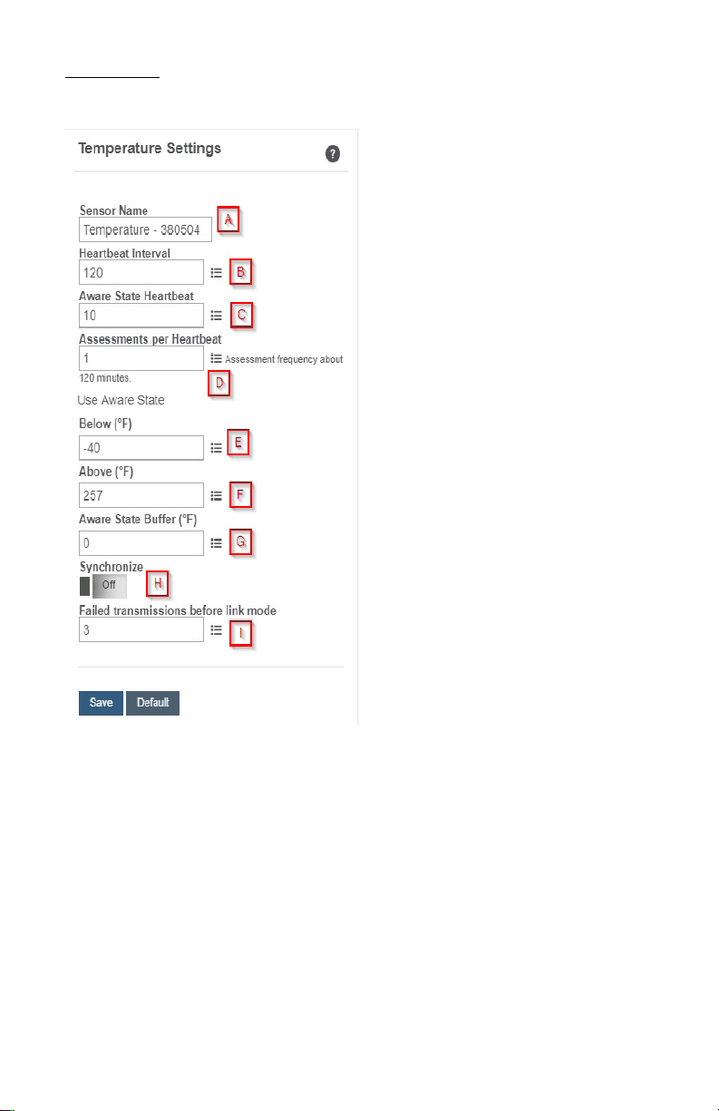
A. Sensor Name is a unique name you
give the sensor to easily identify it in a list
and in any notications.
B. The Heartbeat Interval is how
often the sensor communicates with the
gateway if no activity is recorded.
C. Aware State Heartbeat is how
often the sensor communicates with the
gateway while in an Aware State.
D. Assessments per Heartbeat is how
many times between heartbeats a sensor
will check its measurements against its
thresholds to determine whether it will
enter an Aware State.
E. Below is the minimum reading the
sensor should record before entering an
Aware State.
F. Above is the maximum reading the
sensor should record before entering an
Aware State.
G. The Aware State Buer is a buer
to prevent the sensor from bouncing
between Standard Operation and Aware
State when the assessments are very
close to a threshold. For example, if a
Maximum Threshold is set to 90° and the
buer is 1°, then once the sensor takes
an assessment of 90.1° it will remain in an
Aware State until dropping to 89.0°.
Similarly at the Minimum Threshold the temperature will have to rise a degree above the
threshold to return to Standard Operation.
H. In small sensor networks the sensors can be set to synchronize their communications.
The default setting o allows the sensors to randomize their communications therefore
maximizing communication robustness. Setting this will synchronize the communication of
the sensors.
I. Failed transmissions before link mode is the number of transmissions the sensor
sends without response from a gateway before it goes to battery saving link mode. In link
mode, the sensor will scan for a new gateway and if not found will enter battery saving
sleep mode for up to 60 minutes before trying to scan again. A lower number will allow
sensors to nd new gateways with fewer missed readings. Higher numbers will enable the
sensor to remain with its current gateway in a noisy RF environment better. (Zero will cause
the sensor to never join another gateway, to nd a new gateway the battery will have to be
cycled out of the sensor.)
PAGE 11
Page 14
The default heartbeat interval is 120 minutes or two hours. It is recommended that you do
not lower your heartbeat level too much because it will drain the battery.
Finish by selecting the “Save” button.
Note: Be sure to select the “Save” button anytime you make a change to any of the sensor parameters. All
changes made to the sensor settings will be downloaded to the sensor on the next sensor heartbeat (checkin). Once a change has been made and saved, you will not be able to edit that sensor’s conguration again
until it has downloaded the new setting.
Calibrate View
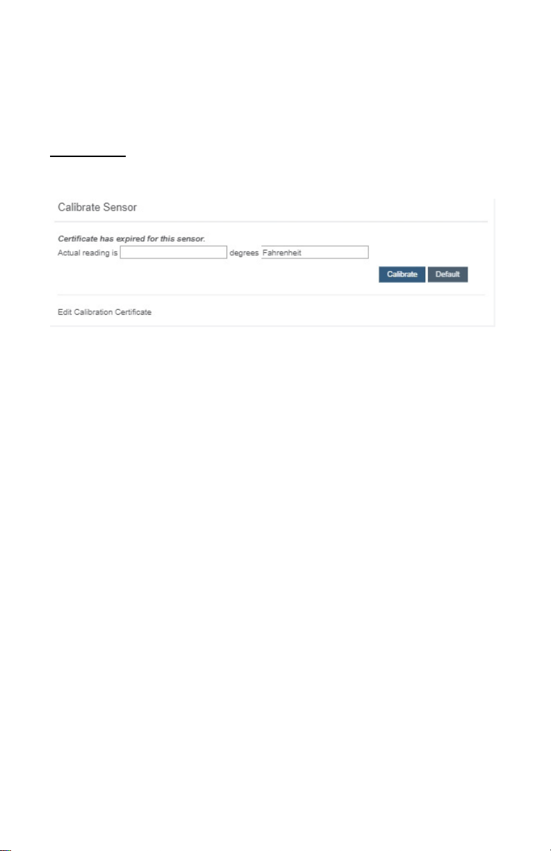
If a sensor type has readings that need to be reset, the “Calibrate” tab will be available for
selection in the sensor tab bar.
To calibrate a sensor, you will want to ensure that the environment of the sensor and other
calibration device is stable. Note the “Expected Next Check-in” time for the sensor you
are calibrating and take a reading from your calibration device a few minutes prior to the
sensors next check-in.
Enter the actual (accurate) reading from the calibration device into the text eld. If you need
to change the unit of measurement you can do that here.
Press “Calibrate”.
To ensure that the calibration command is received prior to the sensors next check-in,
press the control button on the back of the gateway, once, to force communication (Cellular
and Ethernet gateways).
After pressing the "Calibrate" button and choosing the gateway button, the server will send
the command to calibrate the specied sensor to the gateway. When the sensor checks-in,
it will send the pre-calibration reading to the gateway, then receive the calibration command
and update it’s conguration. When the process is completed, it will send a “Calibration
Successful” message. The server will display the sensor’s last pre-calibrated reading for
this check-in, then all future readings from the sensor will be based on the new calibration
setting.
It is important to note that after calibrating the sensor, the sensor reading returned to the
server is based on pre-calibration settings. The new calibration settings will take eect on
the next sensor heartbeat.
Note: If you would like to send the changes to the sensor right away, please remove the battery(s) for a full 60
seconds, then re-insert the battery(s). This forces the communication from the sensor to the gateway and this the
message to make a change from the gateway back to the sensor. (If the sensors are industrial sensors, turn the
sensor o for a full minute, rather than removing the battery).
PAGE 12
Page 15
Creating a Calibration Certicate
Creating a sensor calibration certicate will mask the calibration tab from those who should
not have permissions to adjust these settings. Permissions for self-certifying a calibration
must be enabled in user permissions.
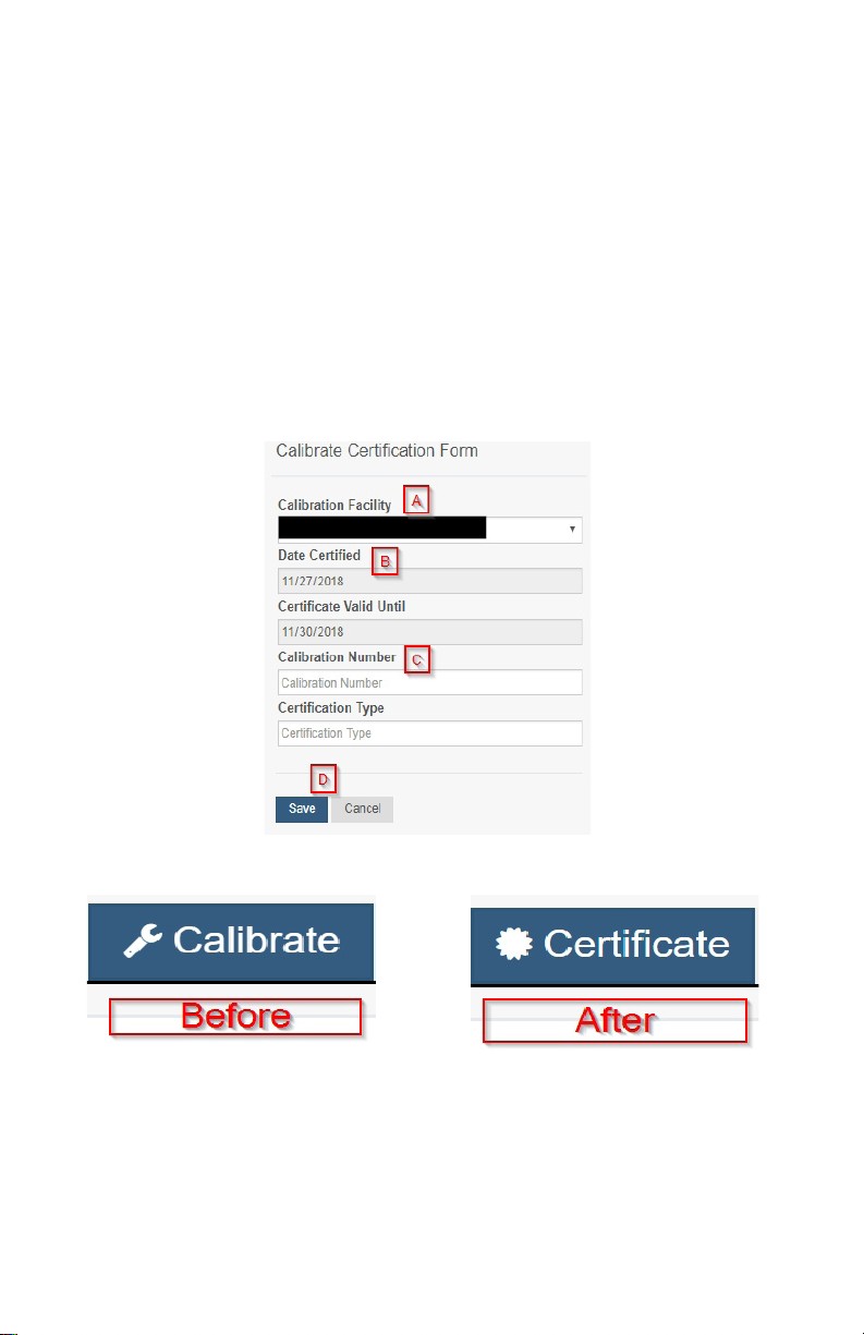
Directly below the calibrate button is the selection to "Create Calibration Certicate.
A. The Calibration Facility Field will be lled. Select the dropdown menu to change your
facility.
B. The date for "Certicate Valid Until" must be set one day in the future after the date
contained in the "Date Certied" eld.
C. "Calibration Number" and "Calibration Type" are unique values to your certicate.
D. Choose the "Save" button before moving on.
When the new certicate is accepted, the Calibration tab will change to a Certicate tab.
You will still be able to edit the certicate by choosing the Certicate Tab and navigating
down to "Edit Calibration Certicate."
The tab will revert back to "Calibrate" after the period for the certicate ends.
PAGE 13
Page 16
Scale View
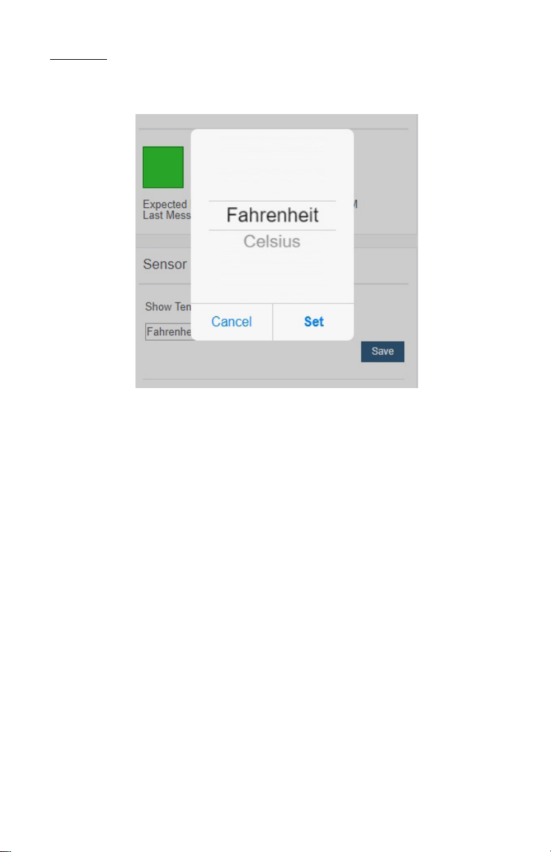
If the sensor settings are inuenced by temperature, the scale option will be available in the
tab bar. To change the temperature unit of measurement from Fahrenheit to Celsius or vice
versa, select the Scale tab.
Choose the text box to trigger a pop-up window allowing you to change the scale. Select
the scale you prefer and push “Set.”
Press the “Save” button to complete your adjustment.
PAGE 14
Page 17
V. GATEWAY OVERVIEW
HOW GATEWAYS WORK
A gateway is the device that manages communication between your sensors and servers.
On startup, the gateway will periodically transmit a heartbeat, checking in with the servers
to make sure it is still receiving an active signal. Sensors also have heartbeats and will
relay information to the gateway, which then forwards the data to the server. There are four
dierent types of gateways:
• Cellular Gateways: Uses cell towers to facilitate communication between
gateways and the monitoring system.
• Ethernet Gateways: Requires an ethernet cable to establish a connection
between your gateway and Monnit Servers using an IEEE 802.3 network.
• USB Gateways: Uses an existing internet connection on a PC to facilitate
communication with the Monnit servers.
• Serial Modbus Gateway: Acts as a data concentrator for Monnit wireless
sensor networks.
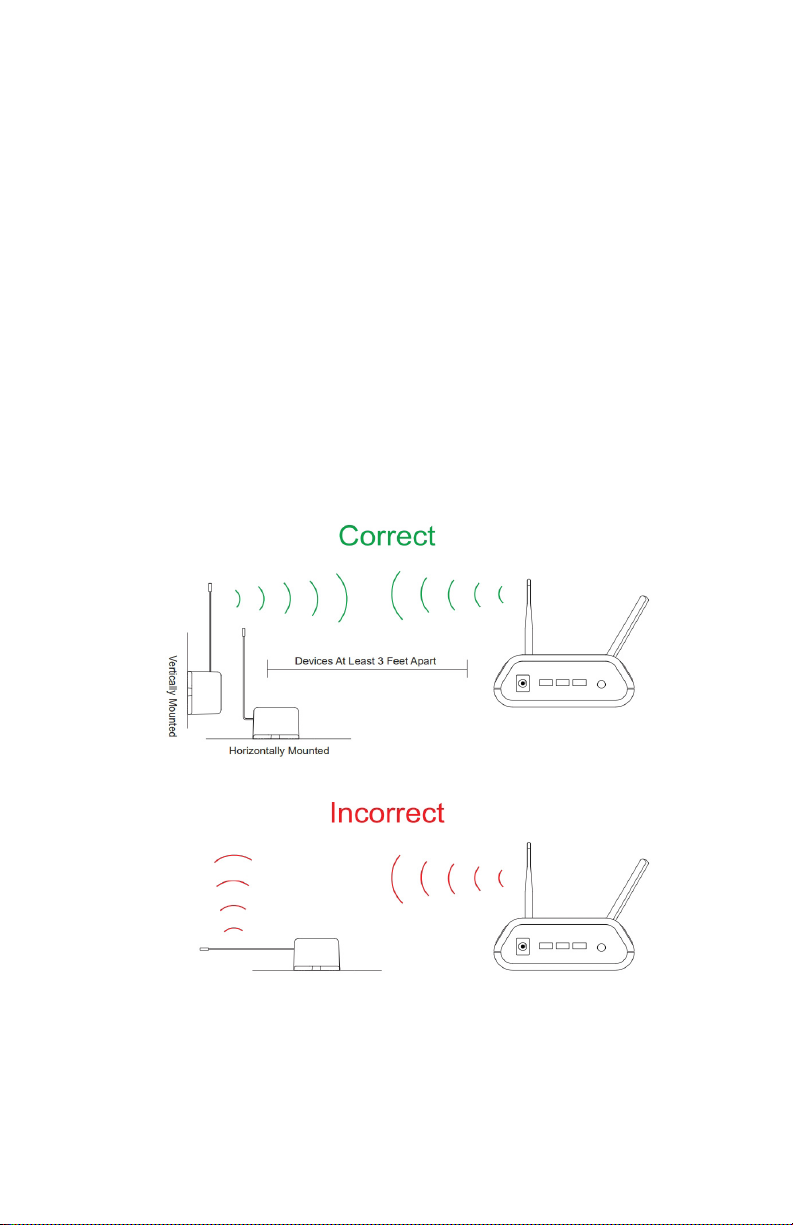
In order for your wireless sensors to work optimally, you should orient all antennas for your
sensor(s) and gateway(s) the same direction (typically vertical). Also, sensors must be
at least three feet away from other sensors and the wireless gateway in order to function
properly.
PAGE 15
Page 18
GATEWAY SETTINGS
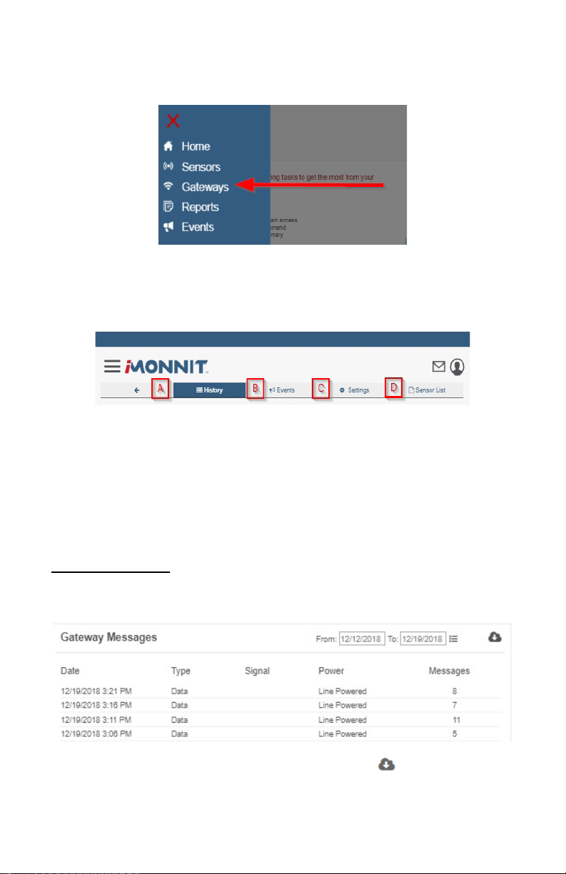
On iMonnit, nd Gateways in the main navigation menu to start modifying your gateway
settings.
A list of all the gateways registered to your account will display. There should be at least
one gateway registered to your account in order for your sensors to be active.
Select one of your gateways from the list. There will be a series of tabs allowing you to view
the status of your gateway and make changes.
A. History – This will be the rst page to display. With a list of data received from previous
heartbeats. If there have been any alert states in the past, they will show up here.
B. Events – This will display a list of all the events you have under this gateway. If you
have not assigned any events to this gateway, the page will be blank.
C. Edit – If you would like to make changes to your gateway network connection, you can
do so here under the Settings section.
D. Sensor List – Here you will see a list of sensors registered to the gateway. If there
aren’t sensors registered to the gateway, the list will be blank.
Gateway History View
The rst tab to display when entering your gateway will be the History tab, allowing you to
view gateway messages as time stamped data.
• On the far right of the gateway history data is a cloud icon. Selecting this icon
will export an excel le for your sensor into your download folder.
Note: Make sure you have the date range for the data you need input in the “From” and “To” text boxes. This will be
the most recent week by default. Only the rst 2,500 entries in the selected date range will be exported.
PAGE 16
Page 19
Gateway Event View
All events assigned to the gateway can be found by selecting the Events tab. If there are
no active events, none will be listed for the gateway. From here you have the option of
selecting an event to edit, pausing notications, or delaying alerts for one hour. For more on
creating and editing event notications, see the Event section of this guide.
Gateway Settings View
Select the Settings tab to enter gateway settings. Depending on the gateway model, there
may be a dierent collection of general settings available for modication.
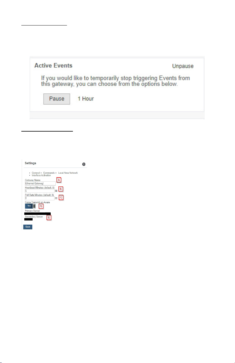
Ethernet Gateway General Settings
A. The Gateway Name eld is where you assign your
gateway a unique title. By default, the gateway name will
be the type followed by the Device ID.
B. The Heartbeat Minutes congures the interval that
the gateway checks in with the server. The default is ve
minutes. So, every ve minutes your gateway will report
to the server.
C. The Poll Rate Minute setting only applies if you are
using Monnit Control or Monnit Local Alert. Here’s how
it works: to conserve cellular data, your gateway has a
set heartbeat (meaning it only exchanges data with the
iMonnit server once every ve minutes by default). If you are using Monnit Control or
Monnit Local Alert, you may want to control equipment or receive local alerts more
frequently. If you were to increase your gateway heartbeat, you would increase your data
usage substantially.
Setting a poll rate allows your gateway to check for priority incoming messages more
frequently — while using a fraction of the data of a regular message exchange. Your
gateway asks the iMonnit server if there are any priority incoming messages, and if there
are, they are exchanged immediately. If not, no messages are exchanged until your
gateway has its next regular heartbeat.
D. Force Transmit on Aware means that if the sensors reach an aware state outside
of the ve minute heartbeat interval, the gateway will immediately relay that data to the
server instead of waiting the extra time it would take to reach the next heartbeat minute.
E. The Primary Server is the main server your gateway is programmed to communicate
with. The Secondary Server is the next server the gateway will issue communication
through if it cannot contact the Primary Server.
PAGE 17
Page 20
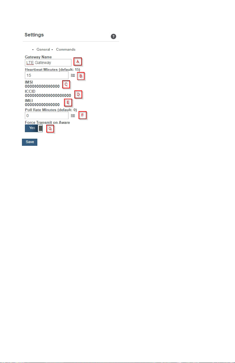
Cellular Gateway General Settings
A. The Gateway Name eld is where you
assign your gateway a unique title. By
default, the gateway name will be the type
followed by the Device ID.
B. The Heartbeat Minutes congures the
interval that the gateway checks in with
the server. The default is fteen minutes.
So, every fteen minutes your gateway
will report to the server.
C. The Global System for Mobile
Communications utilizes a fteen digit
IMSI (International Mobile Subscriber
Identity) number as the primary mode
to identify the country, mobile network,
and subscriber. It is formatted as MCCMNC-MSIN. MCC is the Mobile country
Code. MNC is the Mobile Network Code
attached to the cellular network. MSIN is a
sequential serial number making the IMSI
unique to a subscriber.
D. The ICCID is the nineteen digit unique identication number corresponding to the cellular
SIM card. It is possible to change the information contained on a SIM (including the IMSI),
but the identity of the SIM itself remains the same.
E. IMEI (International Mobile Equipment Identity) is a number exclusive to a Cellular
Gateway to identify the gateway to the cell tower. The Global System for Mobile Communi-
cations network stores the IMEI numbers in a database (EIR - Equipment Identity Register)
containing all valid cellular equipment.
F. The Poll Rate Minute setting only applies if you are using Monnit Control or Monnit
Local Alert. Here’s how it works: to conserve cellular data, your gateway has a set heartbeat (meaning it only exchanges data with the iMonnit server once every ve minutes by
default). If you are using Monnit Control or Monnit Local Alert, you may want to control
equipment or receive local alerts more frequently. If you were to increase your gateway
heartbeat, you would increase your data usage substantially.
Setting a poll rate allows your gateway to check for priority incoming messages more frequently —while using a fraction of the data of a regular message exchange. Your gateway
asks the iMonnit server if there are any priority incoming messages, and if there are, they
are exchanged immediately. If not, no messages are exchanged until your gateway has its
next regular heartbeat.
G. Force Transmit on Aware means that if the sensors reach an aware state outside of
the fteen minute heartbeat interval, the gateway will immediately relay that data to the
server instead of waiting the extra time it would take to reach the next heartbeat minute.
PAGE 18
Page 21
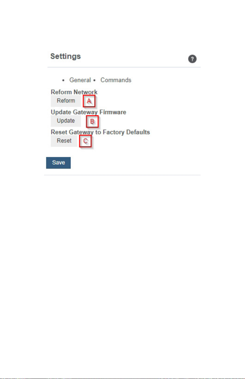
Commands
Choose the bullet for Commands located just under the Settings title to access the
commands page.
A. Selecting the Reform Network command will trigger the gateway to remove all
sensors from its internal white-list, and then request a new sensor list from the server.
This command will force all sensors to reinitialize their connection with the gateway.
Reforming the network cleans up communication when multiple networks are in
range of each other so they are all in sync. This is especially useful if you have move
sensors to a new network, and would like to clear these sensors from the gateways
internal list. Reforming the network will place a new list of sensors that will continue to
exchange data.
B. If there are updates available for your gateway rmware, the Update Gateway
Firmware button will appear, giving you the option to select it and install the latest
rmware.
C. Choosing the Reset Gateway to Factory Defaults button will erase all your unique
settings and return the gateway to factory default settings.
PAGE 19
Page 22
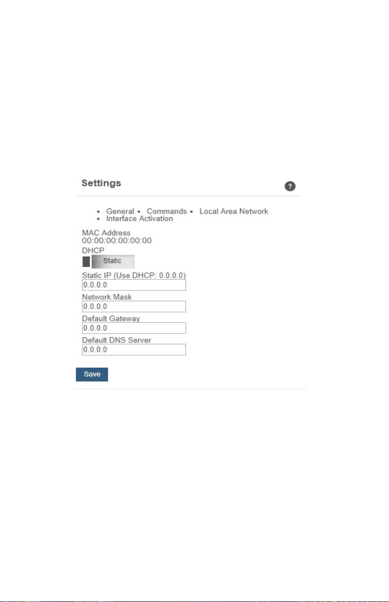
Local Area Network
Choose the Local Area Network bullet under the Settings title to open up the local area
network conguration page. The Local Area Network includes the ability to switch your
network IP address from DHCP to Static. DHCP will be the default network IP address.
Multiple interfaces can be active, but they each need a static IP address on the Gateway.
Internet Service Providers (ISPs) assign IP (Internet Protocol) addresses to a computer
so users can access the Internet. An IP address is a unique number typically formatted
as 000.000.000.0.
To change your IP address to a Static IP, navigate to the network IP option and switch
it from DHCP to Static. Then input your data for the Static IP, Network Mask, Default
Gateway, and Default DNS Server.
Static IP - A static Internet Protocol (IP) address is a numerical sequence assigned to a
computer by an Internet Service Provider (ISP). This is dierent from a Dynamic IP Address
in that a Static IP doesn’t periodically change and remains constant.
Network Mask - More commonly known as a “subnet mask” this number hides the network
half of an IP address. The most common Network Mask number is 255.255.255.0.
Default Gateway - This is the forwarding host a computer utilizes to relay data to the
Internet.
Default DNS Server - DNS Servers take alphanumerical data (like a url address) and dial
the number for the server containing the information you’re looking for.
PAGE 20
Page 23
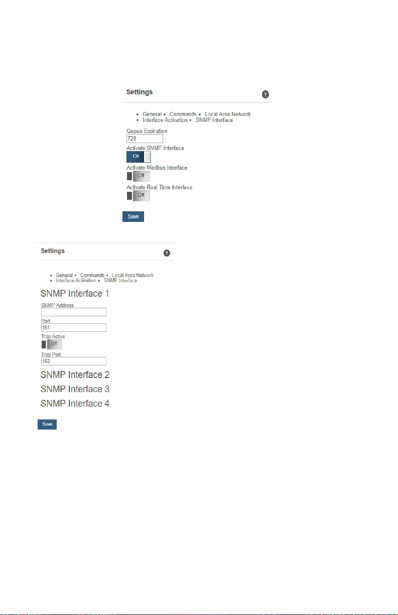
Interface Activation
There are three additional interfaces available for activation on your Gateway Settings
page. To activate them, choose the Interface Activation bullet. Toggle on each of the interfaces to access their individual settings.
SNMP Interface – SNMP (Simple Network
Management Protocol) compiles information from
a variety of clients. This is especially helpful if you
have multiple gateways for devices that need to
communicate with the gateway. Monnit gateways
can manage up to four clients. For more on the
SNMP Interface visit the article SNMP Interface
Conguration. Monnit gateways can manage up
to four clients. The SNMP settings for a gateway
can be adjusted on iMonnit and the oine local
interface. You can continue to use SNMP without
the server interface active. The data will not be
sent to a server, but you can continue to poll for
the data as it is received by the gateway.
• SNMP Address – This is the IP address
for the SNMP Client you wish to communicate with the device. The Enterprise
Gateway has sensor information @ 40101
- 40116 (100 – 115 raw address), and every
16 after in the same pattern; 40117 – 40132
(116- 131 raw) is the next set of 16. Addresses of 0-15, 16-31, 32-47 refer to sensor slots
1, 2 and 3. This is the same as the Register Address of 40001-40016, 40017-40032, and
40033-40048.
• Port - This is the number for where specically in the server data from the
gateway is received. Ports 80 and 443 are reserved for http and https trac. Web
browsers use these ports to send requests to web servers.
• Trap Active – A “Trap” for an SNMP is an alert state sent from your connected
device to the gateway which is then relayed to the server. By default, this option is
o, but you can turn it on by toggling the switch over into the on position.
• Trap Port – The server port where the trap alert state is sent when active.
PAGE 21
Page 24
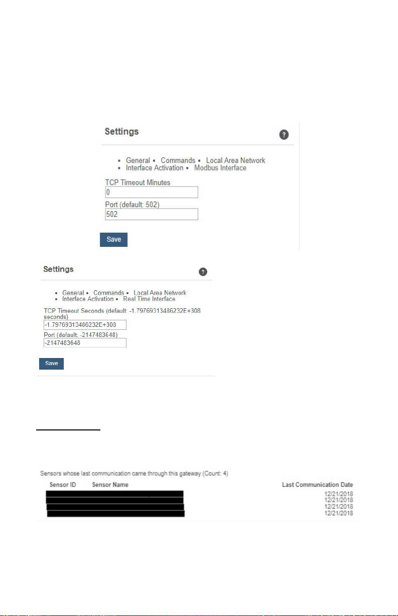
Modbus Interface – Modbus TCP (Transmission Control Protocol) is the Modbus RTU
protocol with a TCP interface that runs on Ethernet. This allows blocks of binary data
to be exchanged between computers. TCP is responsible for making sure all data is
correctly received. IP (Internet Protocol) is responsible for making sure data is correctly
addressed and routed. Monnit provides the Modbus TCP interface for you to pull gateway
and sensor data. You can continue to use Modbus without the server interface active. The
data will not be sent to a server, but you can continue to poll for the data as it is received
by the gateway.
Real-time TCP - Real Time TCP
(Transmission Control Protocol)
guarantees response within a specic
deadline. TCP is responsible for making
sure all data is correctly received by the
IP address. A static IP must be set on
the gateway.
• TCP Timeout Seconds – The
amount of time the gateway waits
for a request to be received by the
server before the session times out
and the connection is refused.
• Port – This is the number for where specically in the server data from the
gateway is received. Ports 80 and 443 are reserved for http and https trac. Web
browsers use these ports to send requests to web servers.
Sensor List View
Choose the Sensor List tab to view a complete count of all sensors reporting to the selected
gateway. This is only a list of the sensors. They cannot be edited from this page.
PAGE 22
Page 25
VI. REPORTS OVERVIEW
Reports are delivered regularly via email, updating you on sensor activity. The interval of
these reports is easy to set and can even be submitted as one-time non-recurring updates.
Regular reports help you stay up to date on your sensor activity. This guide will walk you
through setting up a battery health report. You can use the same steps to set up other
reports as needed. Some parameters will dier slightly depending on the type of report you
select.
ADDING A REPORT
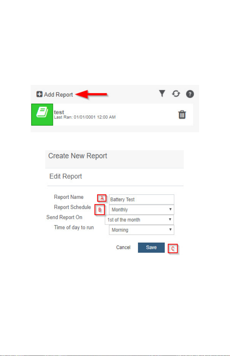
• To create a new report, select "Add Report" in the upper left-hand corner.
• Next you will select the report type from the drop down menu. This guide uses a Battery
Health Report as an example :
A. The rst step will be to add a title for your report.
B. When creating the report, you will be asked to input a title and when you want the report
delivered. You have several options for selecting when you want the report generated. You
can also customize what time of day you would like to receive the report; Morning, Mid-day,
Evening, or Night:
Monthly = The 1st, 8th, 15th, or 22nd of every month.
Weekly = Once on the preferred day of the week.
Daily = Every day at the time of your choosing.
Once = A one-time, non-recurring, report.
C. Selecting "SAVE" will immediately add your new test to the list where you can continue
to edit, view report history, and customize recipients.
PAGE 23
Page 26
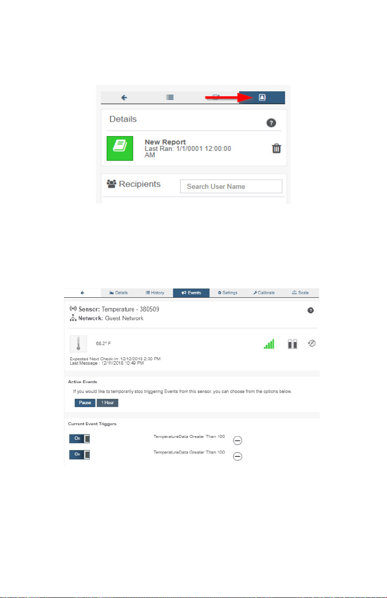
Your user will automatically be added as a recipient of the report. To add other users rst,
make sure they have been added to the account then click on the name of the report you
want to manage.
• Choose the Report Recipients tab.
• Select the other users you would like to also be notied when the report runs.
VII. EVENTS OVERVIEW
Notications for a single sensor or gateway can be created, deleted, and edited by
selecting the “Events” tab in the sensor tab bar.
You can toggle the Event Trigger on or o by selecting the switch under Current Event
Triggers.
PAGE 24
Page 27
CREATING AN EVENT
Events are triggers or alarms set to let you know when a sensor reading identies that
immediate attention is needed. Types of events include sensor readings, battery level,
device inactivity, and scheduled data. Any one of these can be set to send a notication or
trigger an action in the system.
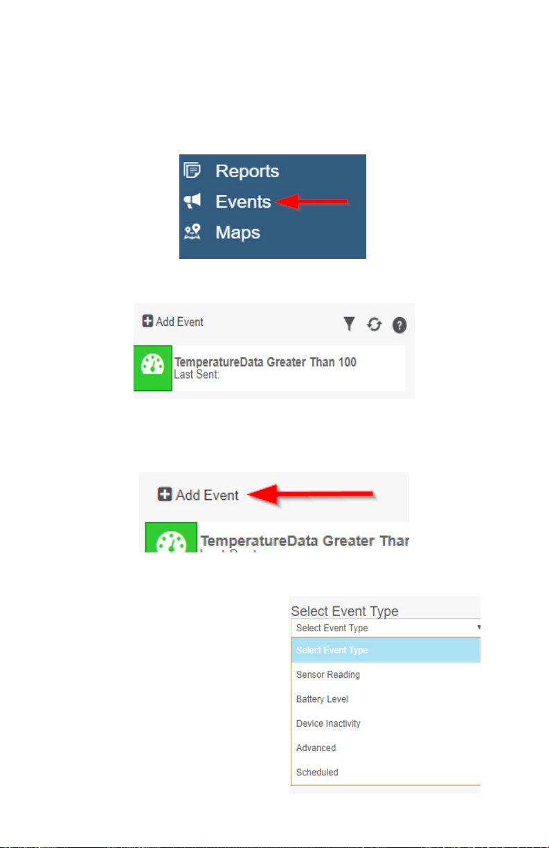
1. Select Events in the main navigation menu.
2. A list of previously created events will display on the screen. From here, you have the
ability to lter, refresh, and add new events to the list.
Note: If this is your rst time adding an event, the screen will be blank.
3. From the Events page, tap “Add Event” in the left hand corner.
4. The dropdown menu will have the following options for Event Types:
• Sensor Reading: Set alerts based on
sensor activity or reading.
• Battery Level: This is where you can set
to be notied whend the battery level drops
below a percentage. 15% is the default
setting.
• Device Inactivity: Alerts when the device
doesn’t communicate for an extended
period of time.
• Advanced: Alerts based on advanced rules, such as comparing past data
points with current ones.
• Scheduled: These are notications that
re at a time set basis.
PAGE 25
Page 28
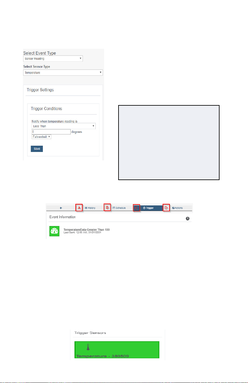
5. Select Sensor Reading from the dropdown menu.
6. A second dropdown menu will appear. From here, you will be able to see a list of the
dierent type of sensors registered to your account. Choose Temperature in the dropdown
menu.
7. Next, you will be asked to input the trigger
settings. You have the option of setting this trigger
for greater than or less than a temperature reading
8. Press the “Save” button.
If you don’t have a temperature sensor, the option in this
example won’t be available, select any variable output
sensor and follow along.
Variable output sensors can have multiple event triggers
created.
Example: A temperature sensor used in a freezer.
You may want to be notied if the temperature goes
below 0° or above 30° Fahrenheit. You would create
two events.
• Event 1- Trigger Set for temperatures LESS THAN
0°F.
• Event 2 - Trigger set for temperatures GREATER
THAN 30° F.
9. The Event Information page has a series of tabs across the top.
A. History: A table of all past alert notications for this specic event.
B. Schedule: Here you can schedule the event only to be active at certain times or
certain days.
C. Trigger: This is where you can review your trigger settings.
D. Actions: Where you set the action you want to happen when an alert state is
triggered.
10. Choose the Trigger tab.
11. The Trigger Sensors section sits below “Trigger Conditions.” If you have multiple
sensors for the same type (Example: ve temperature sensors), this is where they will be
listed. There should be at least one sensor in this section.
PAGE 26
Page 29
12. By default, the sensor(s) will not be assigned to the event conditions you’ve just set. To
assign a sensor, nd the device(s) you want to designate for this event and select. Selected
sensor boxes will turn green when activated. Choose the sensor box again to unassign the
sensor from the event.
13. Continue toggling the sensor(s) corresponding to this new event until you are satised
with your selection. These can be adjusted later by returning to this page.
14. Press the “Save” button.
15. Select the Actions tab.
16. Press the Add Action button under the Event Information header and available action
types are presented in a select list.
• Notication Action: Specify account users to recieve notications when this event
triggers.
• System Action: Assign actions for the system to process when this event triggers.
17. Choose Notication Action from the notication list.
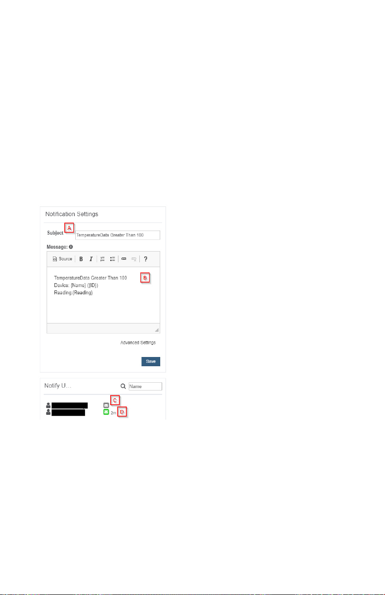
A. Congure the subject for the notication.
B. Customize the message body for the notica-
tion
C. Save button commits any changes to message
content elds.
D. Recipient list identies who will recieve the
notication.
• Select the icon next to a user to congure
how they will be notied
• Choose if you want notications sent
immediately when triggered or if you want
a delay before it is sent and press Set.
• A green icon indicates the users that will
not recieve the notications.
• If a delay has been selected, the delay
time will display beside the icon.
PAGE 27
Page 30
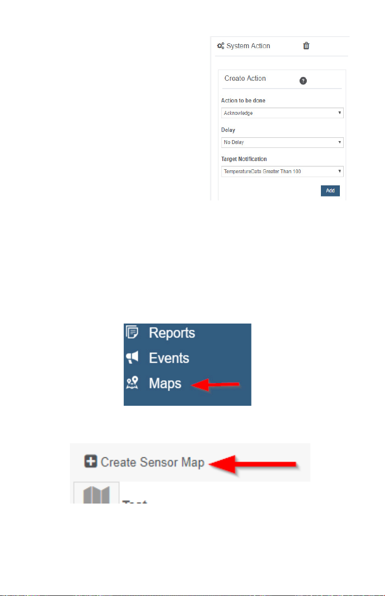
18. Select System Action from the select list
under the Event Information header.
19. Scroll down to the System Action section.
20. The Action to be Done select list has the
following options.
• Acknowledge: Automatically signal
that you have been notied of an
event and take action. When an
event has been triggered, actions will
continue processing until the event
returns to a value that no longer
triggers an event.
• Full Reset: Reset your trigger so it is
armed for the next reading.
• Activate: Enable an event trigger.
• Deactivate: Disable an event trigger.
VIII. SENSOR MAPS OVERVIEW
The Maps feature gives you the option of uploading your oorplan or other image to iMonnit®
and allows you to virtually position sensors where you have physically placed sensors in the
location. This is useful if you have multiple sensors and want to know see them in context of
where they are placed. This guide will walk you through uploading a oorplan and positioning
sensors.
CREATING A SENSOR MAP
1. Find the main navigation menu and select “Maps.”
2. All previously created sensor maps will display.
3. To create a new sensor map, locate “Create Sensor Map” in the top left-hand corner.
PAGE 28
Page 31
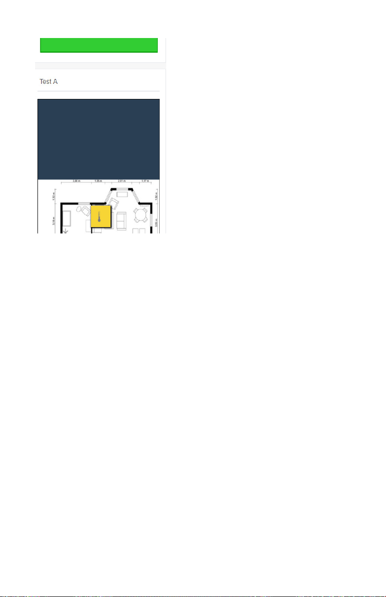
• The following page will ask you to enter
a title for your new sensor map.
• Next you will upload a picture of your
oorplan. Acceptable image formats are:
bmp, gif, jpg, png, ti.
• Selecting "Create Map" will guide you
to the Edit Sensor Map screen.
• The following screen will be the Edit
Map page. Choose the button for the
sensor you want to add to the map. The
button will turn green and the sensor icon
will appear on the map. You can then drag
it to the designated location on the map.
Secondary selection of the icon will open
a menu with additional options. Once your
sensors are in you the desired locations,
proceed to view the map.
• Select the View Map tab to open a
window showing your whole oorplan with
the sensors.
• You cannot move sensors when you are on the View Map page. This can only be
done on the Edit Map Page.
• Select the back button in the tab bar at the top of the page to be guided back to
the Maps homepage.
• Selecting "Create Map" will guide you to the Edit Sensor Map screen.
• The following screen will be the Edit Map page. To place a sensor, choose the
sensor you want to replace. The sensor will turn green and you will be allowed to
place a yellow square representing the sensor where it is located on your oorplan.
• Select the View Map tab to open a window showing your whole oorplan with the
sensors.
• You cannot move sensors when you are on the View Map page. This can only be
done on the Edit Map Page.
• Select the back button in the tab bar at the top of the page to be guided back to
the Maps homepage.
PAGE 29
Page 32
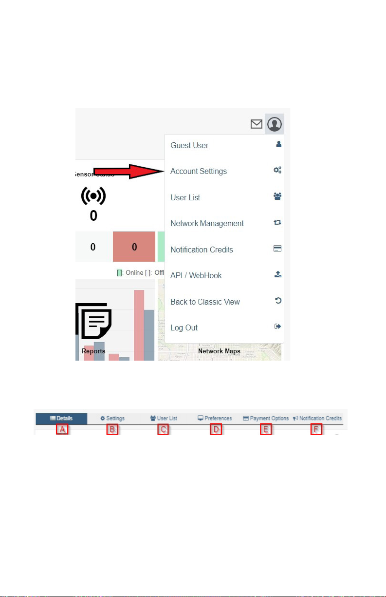
IX. ACCOUNT MENU
Account Settings is where you can edit any account information. From this easy to use
page, you can congure account parameters, manage users, set account level preferences,
and manage your notication credits.
The “Account Menu” is where you can access various administrative functions pertaining to
your iMonnit account. Select the prole symbol in the top right to open the menu.
ACCOUNT SETTINGS
Access Account Settings by nding the section in the Account Menu. Across the top of
the page, you will see the tab bar:
A. Account Details contains all your current user information, in addition to your active
subscription expiration dates and the link to purchase iMonnit Premiere.
B. The Settings tab allows you to change your account information.
C. The User List tab will list all users who have access to the account.
D. Account Preferences is a new feature and new preferences will be added so check
back often.
E. Payment Options gives you the freedom to review sources of payment for your Monnit
Store account.
F. The Notication Credits tab will display all the settings for credits needed to participate
in Direct SMS, and Voice.
PAGE 30
Page 33
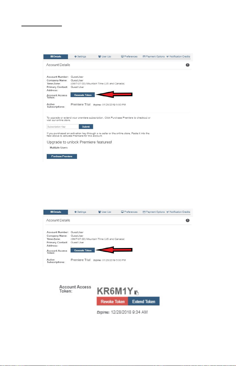
Account Details
The Account Details page will be the rst page you see. This section will contain all the
account information you entered when registering for your account. This is where you will
manage your account when you need to upgrade or renew subscriptions.
Generating a Token
If you ever have to call into Monnit Technical Support, you may be asked to provide an
Account Access Token. An Access Token is an alphanumerical code valid for 24 hours so
Monnit support can assist with issues on the account. It can be extended or revoked if the
problem is solved no longer wish to grant access.
• Select Account Settings and navigate down to the “Generate Token” button.
• Choose the button to receive the unique access code.
The code will automatically expire in 24 hours. Selecting the Extend button will grant a one-
time week-long extension period before mandatory expiration. Choose the Revoke Token
button to end access prior to the expiration date.
PAGE 31
Page 34
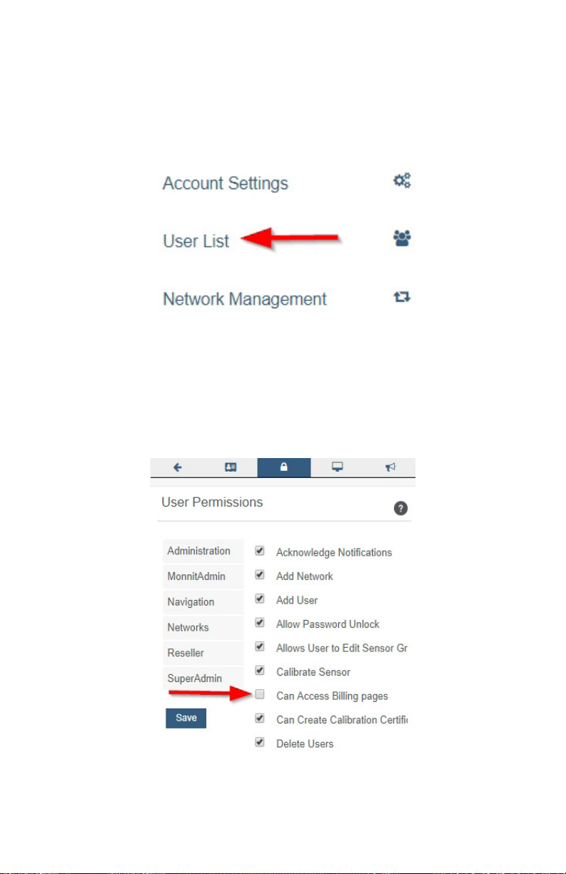
Renewing an iMonnit Subscription
Monnit Premiere Subscriptions are given out on a yearly basis. When it is time to renew, an
email notication will be sent to let you know the subscription is about to expire.
You will need to verify that you have permission to create a certication before launching
into the process. Do this by navigating up to the account menu and selecting “User List.”
Locate your account in the list. If you have a basic account, your name as the primary
account holder will be the only one on the list. The availability of multiple users registered to
one account is a feature only available on iMonnit Premiere.
Once in your account page, choose the User Permissions tab.
Verify that the checkbox for “Can Access Billing Pages” is checked. If the box is empty,
check it and be sure to select the “Save” button before moving on.
You must have a Monnit Store Account to renew your subscription. If you already have a
login for the Monnit Store you may proceed on to the next section.
PAGE 32
Page 35
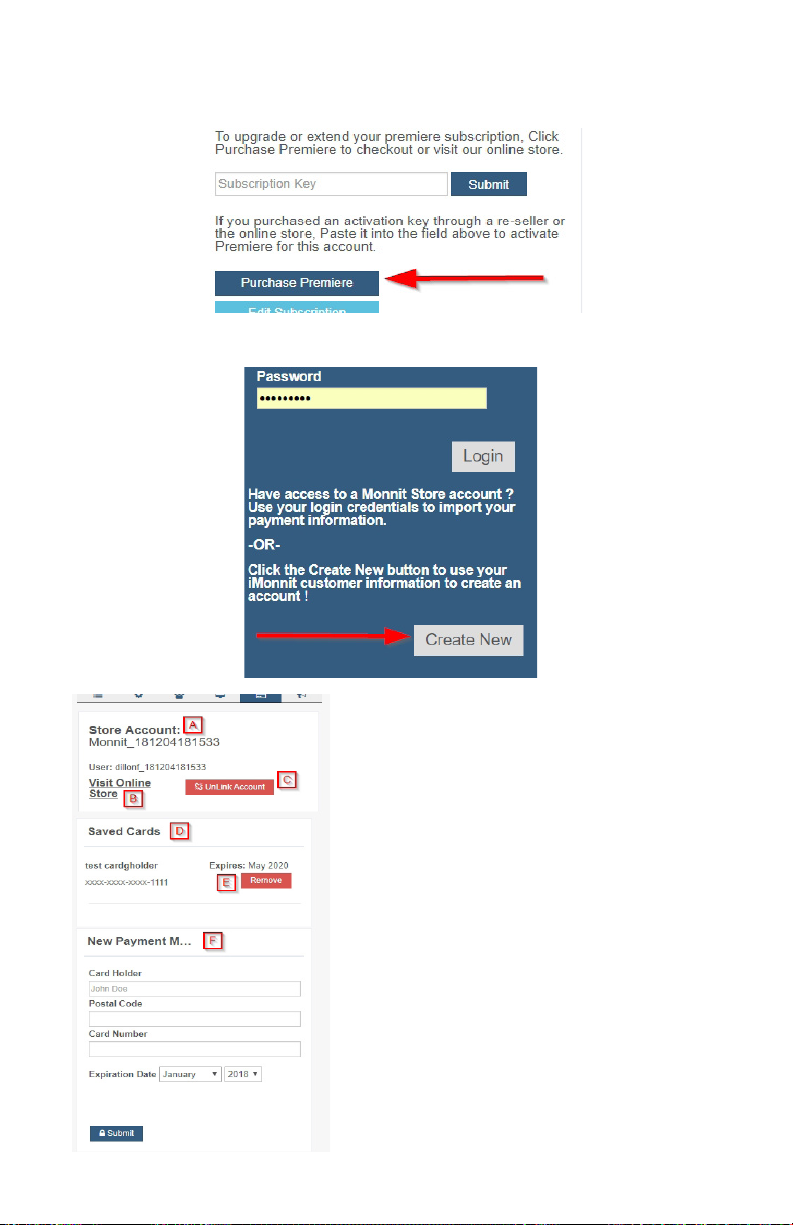
Return to the Account Settings’ Details page. Find the “Purchase Premiere” button located
beneath the Subscription Key text box.
The login page will load. Navigate over to the “Create New” button and select.
A. The new store name will be a combination between
your iMonnit user name and the twelve-digit time
stamp for when you created the account.
B. Select this link to visit the online store and see what
sort of options are out there to buy.
C. Unlinking your account will take you back to the
login page.
D. If you have used any credit cards in the past, they
will appear in the Saved Cards section.
E. Remove previously saved cards in this section by
selecting the “Remove” button.
F. If you would like to add a card, just enter your
name, postal code, card number, and expiration date.
Then select the Submit button.
PAGE 33
Page 36
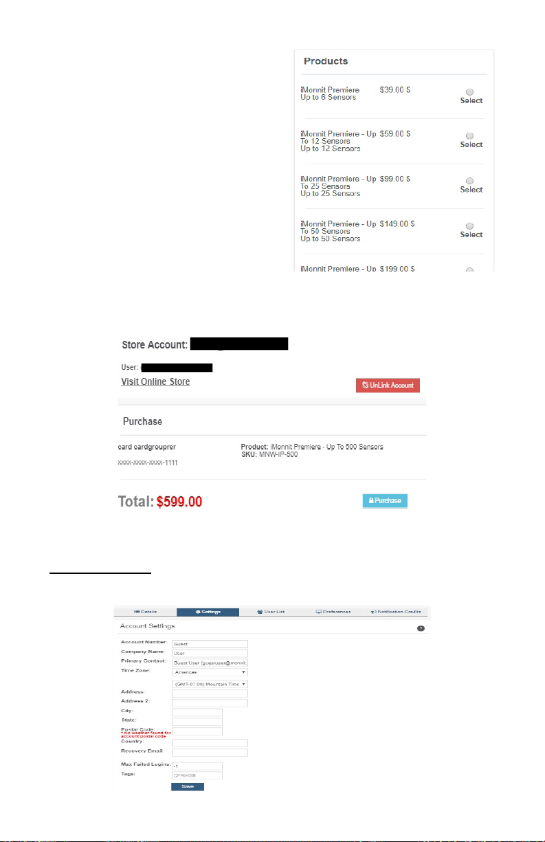
After you enter your card holder information, you
can now move on to purchase a subscription to
your account.
In the products section, you will see a list of
iMonnit Premiere software. You must purchase
a premiere account greater than the number of
sensors registered to your account. If you have
seven sensors, you cannot purchase “iMonnit
Premiere for Up to 6 Sensors.” You need to
select “iMonnit Premiere for Up to 12 Sensors” to
support all your devices.
• Choose a radio button for the
subscription you wish to purchase.
• Select the “Checkout” button.
You’ll be brought to the purchase screen.
The purchase screen will give you one last chance to review your shopping cart. Sales
tax is automatically placed into the calculation of the price. This is software, so there is no
added shipping cost. If everything meets your expectations, select the “Purchase” button.
The new subscription will be added to the list of Active Subscriptions on the Account Details
tab.
Account Settings
Select the Settings tab to modify incorrect personal account information.
PAGE 34
Page 37
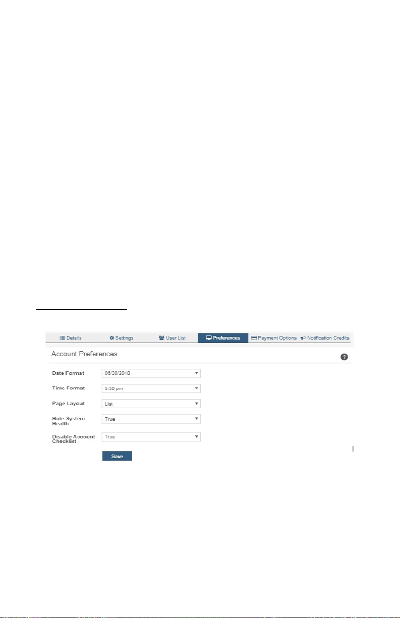
Account Number: This is a unique number for your account. If there is no account number,
this entry will be the same as your name.
Company Name: This is an optional eld for the Company Name. If there is no Company
Name present this eld will be the same as your name.
Primary Contact: This eld displays your name along with your email. This a mandatory
eld as there must be a primary contact for the account to remain active so notications
can be sent.
Time Zone: There are a number of settings in iMonnit that are dependent on time. Set the
time zone for your account here by rst selecting a region and then a zone from the drop-
down list.
Address, City, State, Postal Code, Country: These next few elds apply to your physical
street address.
Recovery Email: An optional eld for a secondary email address if your primary email
cannot be reached.
Reseller: Check this box if you are a veried reseller.
Max Failed Logins: The maximum number of failed login attempts you wish to allow in
order to protect your account from being hacked.
Remember to press the “Save” button after making any changes.
Account Preferences
Select the Preferences tab to adjust selections to t your unique taste.
Date Format: Pick a preferred format to have the date displayed on exports and reports.
Time Format: Dierent from time zone, this option allows you to choose a preferred format
to have the timestamp displayed on exports and reports.
Page Layout: Choose to display page as a list or grid.
Hide System Health: Choose whether or not to hide System Health. True / False.
Disable Account Checklist: Choose whether or not to have a disable account checklist.
PAGE 35
Page 38
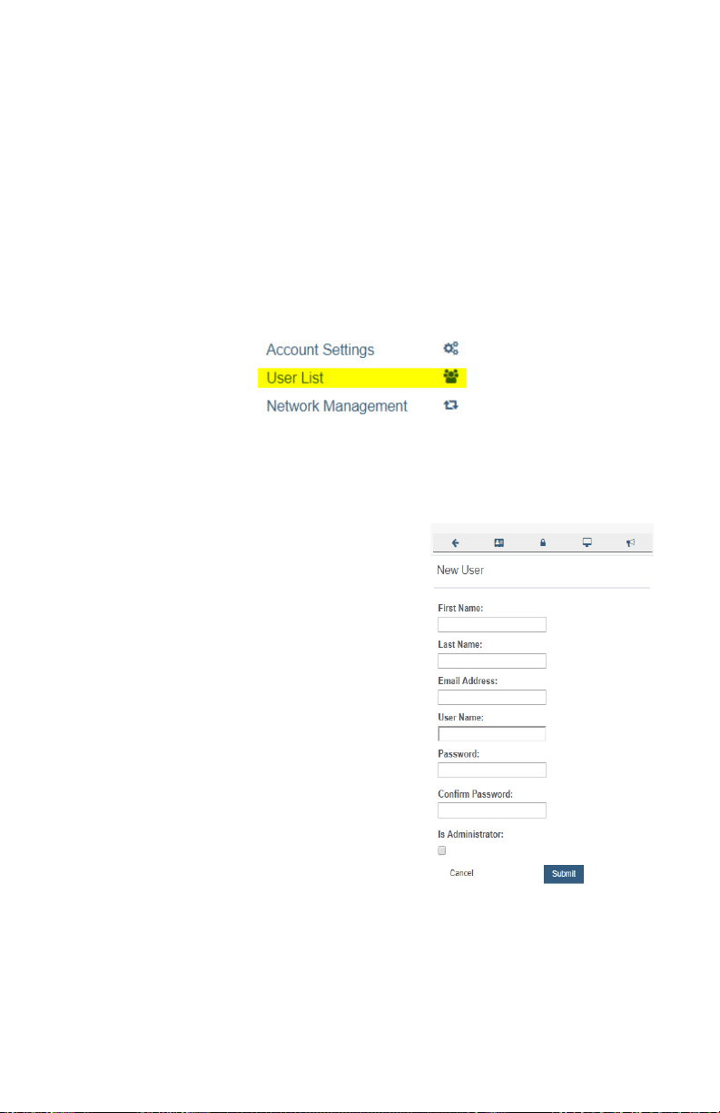
Remember to press the “Save” button after making any changes.
USER LIST
The user list page can be accessed either through the account menu or selecting the User
List tab. The user list will display all users who have access to your account. Basic iMonnit
subscriptions may only have one primary user for the account.
The ability to add users to an account is an exclusive feature of iMonnit Premiere. Having
additional users on an account gives you the chance to act as an administrator and control
what each person is allowed to see and do on the account. This can be extremely helpful if
you have a large company and several people need access to Monnit sensors in the event
of an emergency.
Follow the below steps to add a new user to your account:
1. Find “User List” in the Account Menu.
2. The user list will display all users who have access to the account.
3. Select “Add User” located in the top left corner.
4. The Add User page will appear. You must enter
the new user's account information. If you click out
of this page to another tab, it will not display again.
The User Name will auto populate with the email
address. You will have to change this in the User
Name text box if you prefer it to be dierent.
The password must be at least eight characters.
Checking the box for "Is Administrator" gives
the new user the ability to add new users to the
account. By default, the box is not checked. Leave
this box unchecked if you do not want them to have
this ability.
After you have entered all the account information,
select the "Submit" button.
PAGE 36
Page 39
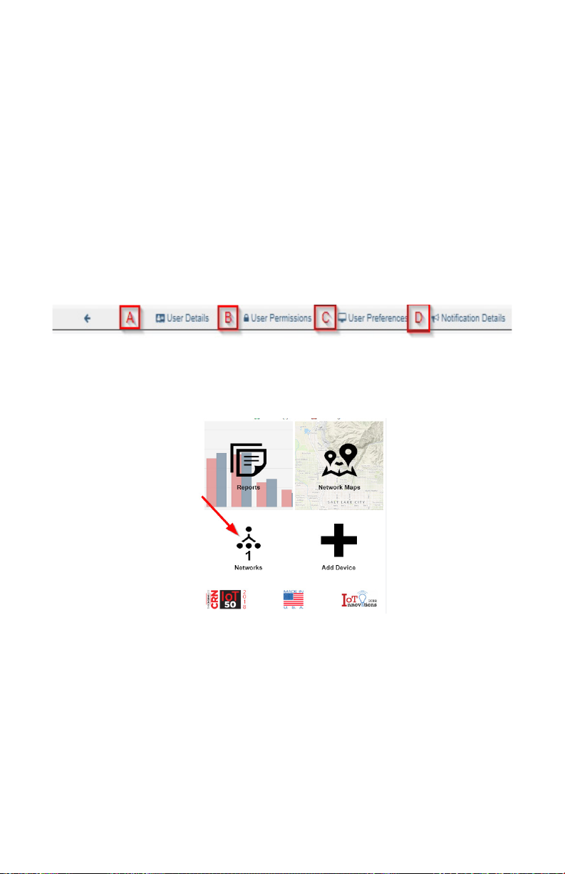
After submitting the new user information, the following tabs will guide you through editing
their settings.
A. User Details lists new user’s account information. This is where the password can be
changed and reset. This information can be downloaded to your computer by clicking the
cloud icon in the upper right corner.
B. User Permissions gives the admin the option of blocking users from having full access to
the site.
Options include: Acknowledge Notications, Edit Gateway Conguration, Password Unlock,
and more.
C. User Preferences is a new feature, check back in the future for more options.
D. Notication Details is where you can adjust settings for how you want to be alerted about
errors in sensors and gateways.
You can receive these alerts over email, text (SMS) messaging, or voicemail. By default,
notications will be o, if not adjusted. Activation can be accomplished by clicking the "Turn
On Notications" button.
NETWORK MANAGEMENT
To view or edit information about your wireless sensor network(s), select the Networks box
in the account overview page or the Network Management option in the account menu.
The following network list page allows you to edit details, create new sensor works, and
manage wireless gateways and sensors for your network(s). Find the network you wish to
modify in the list and select it to be taken to the network edit page.
PAGE 37
Page 40
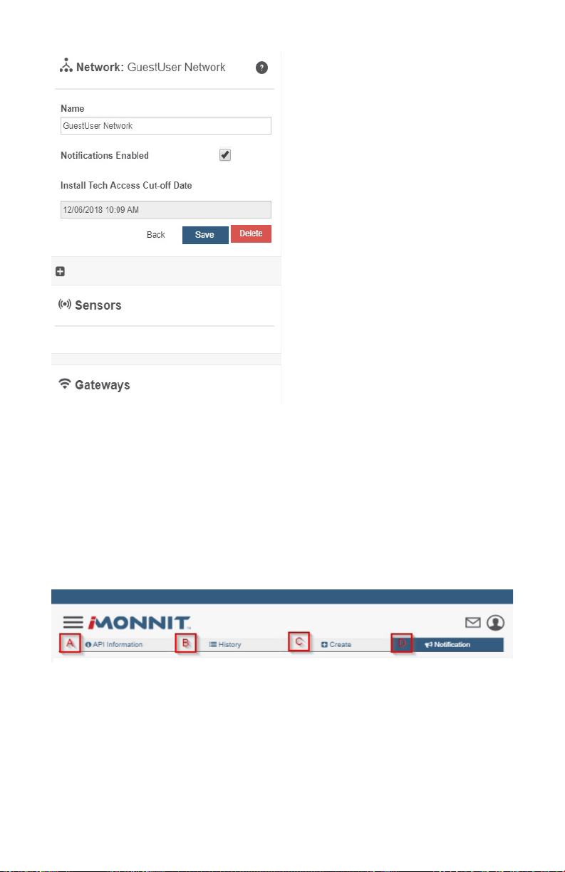
The network edit page will give the option of
changing the name of your network, enable
notications, enable holding, and review the
Install Tech Access Cut-o Date.
Remember, you must press the “Save”
button after making any changes in this
section.
Below this section is a list of sensors and
gateways attached to the account. Choosing
the icon of a trashcan beside each sensor
will delete it from the network. Selecting
the icon directly above the sensor section
will allow new devices to be added to the
network. Review the steps on registering a
new device on page 3 of this user guide.
Note: A sensor or gateway cannot be recovered once it
has been deleted from the network. It is recommended
that you export a sensor’s data history before clearing it
from the list.
API/WEBHOOK
As a Premiere user, you can have Monnit push the sensor readings from iMonnit to your
database with our external conguration tool. This tool allows you to pass data from your
wireless sensor network devices to another service in real time. This is done by coding
the data into a URL query, then sending the data via HTTP get request at the time data is
received. There is an extensive list of parameters that can be passed, allowing you to send
detailed information about both the data and the network.
• Navigate to the API/Webhook Page by opening up the account menu in the top
right corner of the screen. Select API/Webhook.
The API Information page will open. The Tab Bar across the top will read as follows:
A. API Information will be the rst page to appear. Here you can nd information on Data
Push, General Output Format, Gateway Parameters and Sensor Parameters.
B. The History tab displays the history of your data pushes. A Data Push sends data to
your end point when data is received at the server. You can congure the destination and
query parameters used to route the request. Data is compiled as a JSON body and sent
via HTTP POST. There are four (4) endpoints available now. Webhook, Amazon AWS,
Microsoft Azure IoT Hub, and IBM Watson. Only one (1) data push is allowed per account.
If no data push has been congured, this page will be blank.
PAGE 38
Page 41
C. Depending on if you have an existing data push or not this next tab will either read
"Create" or "Edit." If you have an existing data push, this tab will read "Edit" You must end
the existing data push to see the "Create" tab and make a new data push.
D. The Notication Tab covers data push settings that allow you to customize when and to
whom emails are sent when your External Data Push fails multiple times in a row. You will
only be notied once every 24 hours, unless your data push failures exceed 100, in which
case you will be notied of your data push being disabled.
Creating a Webhook
• Select the Create Tab.
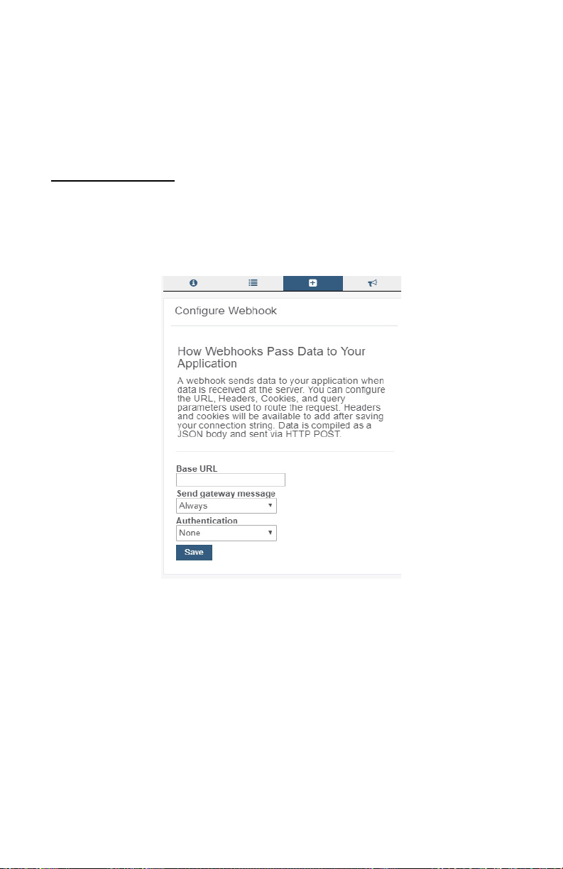
• Open the dropdown menu on the Create Data Type page. Select "Webhook."
• A webhook sends data to your application when data is received at the server.
You can congure the URL, Headers, Cookies, and query parameters used to
route the request. Headers and cookies will be available to add after saving your
connection string. Data is compiled as a JSON body and sent via HTTP POST.
• Base URL: This is the location you want to send the Data Push
• Send gateway message: This is where you decide if you want all messages
sent to you or only messages that contain a message from your sensor
• Authentication: Choose "Basic" or "None" to add authentication to your web-
hook. Selecting "Basic" will ask for the username and password combination to
grant access to the webhook.
• Save your conguration
Note that the tab that used to read "Create" now reads "Edit." The new data push must be
ended for the Create option to be displayed again.
PAGE 39
Page 42

SUPPORT
For technical support and troubleshooting tips please visit our support library online at
monnit.com/support/. If you are unable to solve your issue using our online support, email
Monnit support at [email protected] with your contact information and a description of
the problem, and a support representative will call you within one business day.
For error reporting, please email a full description of the error to [email protected].
WARRANTY INFORMATION
(a) Monnit warrants that Monnit-branded products (Products) will be free from defects
in materials and workmanship for a period of one (1) year from the date of delivery with
respect to hardware and will materially conform to their published specications for a period
of one (1) year with respect to software. Monnit may resell sensors manufactured by other
entities and are subject to their individual warranties; Monnit will not enhance or extend
those warranties. Monnit does not warrant that the software or any portion thereof is error
free. Monnit will have no warranty obligation with respect to Products subjected to abuse,
misuse, negligence or accident. If any software or rmware incorporated in any Product
fails to conform to the warranty set forth in this Section, Monnit shall provide a bug x or
software patch correcting such non-conformance within a reasonable period after Monnit
receives from Customer (i) notice of such non-conformance, and (ii) sucient information
regarding such non-conformance so as to permit Monnit to create such bug x or software
patch. If any hardware component of any Product fails to conform to the warranty in this
Section, Monnit shall, at its option, refund the purchase price less any discounts, or repair
or replace nonconforming Products with conforming Products or Products having substan-
tially identical form, t, and function and deliver the repaired or replacement Product to a
carrier for land shipment to customer within a reasonable period after Monnit receives from
Customer (i) notice of such non-conformance, and (ii) the non-conforming Product provided; however, if, in its opinion, Monnit cannot repair or replace on commercially reasonable
terms it may choose to refund the purchase price. Repair parts and replacement Products
may be reconditioned or new. All replacement Products and parts become the property of
Monnit. Repaired or replacement Products shall be subject to the warranty, if any remains,
originally applicable to the product repaired or replaced. Customer must obtain from Monnit
a Return Material Authorization Number (RMA) prior to returning any Products to Monnit.
Products returned under this Warranty must be unmodied.
Customer may return all Products for repair or replacement due to defects in original
materials and workmanship if Monnit is notied within one year of customer’s receipt of the
product. Monnit reserves the right to repair or replace Products at its own and complete dis-
cretion. Customer must obtain from Monnit a Return Material Authorization Number (RMA)
prior to returning any Products to Monnit. Products returned under this Warranty must be
unmodied and in original packaging. Monnit reserves the right to refuse warranty repairs
or replacements for any Products that are damaged or not in original form. For Products
outside the one year warranty period repair services are available at Monnit at standard
labor rates for a period of one year from the Customer’s original date of receipt.
(b) As a condition to Monnit’s obligations under the immediately preceding paragraphs,
Customer shall return Products to be examined and replaced to Monnit’s facilities, in
shipping cartons which clearly display a valid RMA number provided by Monnit. Customer
acknowledges that replacement Products may be repaired, refurbished or tested and found
to be complying. Customer shall bear the risk of loss for such return shipment and shall
bear all shipping costs. Monnit shall deliver replacements for Products determined by Mon-
nit to be properly returned, shall bear the risk of loss and such costs of shipment of repaired
Products or replacements, and shall credit Customer’s reasonable costs of shipping such
returned Products against future purchases.
PAGE 40
Page 43

(c) Monnit’s sole obligation under the warranty described or set forth here shall be to repair
or replace non-conforming products as set forth in the immediately preceding paragraph, or
to refund the documented purchase price for non-conforming Products to Customer. Monnit’s warranty obligations shall run solely to Customer, and Monnit shall have no obligation
to customers of Customer or other users of the Products.
Limitation of Warranty and Remedies.
THE WARRANTY SET FORTH HEREIN IS THE ONLY WARRANTY APPLICABLE TO
PRODUCTS PURCHASED BY CUSTOMER. ALL OTHER WARRANTIES, EXPRESS
OR IMPLIED, INCLUDING BUT NOT LIMITED TO THE IMPLIED WARRANTIES OF
MERCHANTABILITY AND FITNESS FOR A PARTICULAR PURPOSE ARE EXPRESSLY
DISCLAIMED. MONNIT’S LIABIITY WHETHER IN CONTRACT, IN TORT, UNDER ANY
WARRANTY, IN NEGLIGENCE OR OTHERWISE SHALL NOT EXCEED THE PURCHASE
PRICE PAID BY CUSTOMER FOR THE PRODUCT. UNDER NO CIRCUMSTANCES
SHALL MONNIT BE LIABLE FOR SPECIAL, INDIRECT OR CONSEQUENTIAL DAMAGES. THE PRICE STATED FOR THE PRODUCTS IS A CONSIDERATION IN LIMITING
MONNIT’S LIABILITY. NO ACTION, REGARDLESS OF FORM, ARISING OUT OF THIS
AGREEMENT MAY BE BROUGHT BY CUSTOMER MORE THAN ONE YEAR AFTER
THE CAUSE OF ACTION HAS ACCRUED.
IN ADDITION TO THE WARRANTIES DISCLAIMED ABOVE, MONNIT SPECIFICALLY
DISCLAIMS ANY AND ALL LIABILITY AND WARRANTIES, IMPLIED OR EXPRESSED,
FOR USES REQUIRING FAIL-SAFE PERFORMANCE IN WHICH FAILURE OF A PROD-
UCT COULD LEAD TO DEATH, SERIOUS PERSONAL INJURY, OR SEVERE PHYSICAL
OR ENVIRONMENTAL DAMAGE SUCH AS, BUT NOT LIMITED TO, LIFE SUPPORT OR
MEDICAL DEVICES OR NUCLEAR APPLICATIONS. PRODUCTS ARE NOT DESIGNED
FOR AND SHOULD NOT BE USED IN ANY OF THESE APPLICATIONS.
For more information about our products or to place an
order, please contact our sales department at 801-561-5555.
Visit us on the web at www.monnit.com.
Monnit, Monnit Logo and all other trademarks are property of Monnit, Corp.
© 2019 Monnit Corp. All Rights Reserved.
Monnit Corporation
3400 South West Temple
Salt Lake City, UT 84115
801-561-5555
www.monnit.com
 Loading...