

Page 1
User’s Guide
Shop online at
omega.com
e-mail: [email protected]
For latest product manuals:
www.omegamanual.info
ILD BIG DISPLAY
Monitor / Controller
Communication Manual
Page 2

omega.com [email protected]
Servicing North America:
U.S.A. Omega Engineering, Inc.
Headquarters: Toll-Free: 1-800-826-6342 (USA & Canada only)
Customer Service: 1-800-622-2378 (USA & Canada only)
Engineering Service: 1-800-872-9436 (USA & Canada only)
Tel: (203) 359-1660 Fax: (203) 359-7700
e-mail: [email protected]
For Other Locations Visit omega.com/worldwide
The information contained in this document is believed to be correct, but OMEGA accepts no liability for any errors it contains, and reserves
the right to alter specifications without notice.
Page 3

TABLE OF CONTENTS
Part 1: Before You Begin ....................................................................................2
Part 2: Introduction to Digital Communication.................................................3
2.1 Overview.......................................................................................3
2.2 Definition of Terms ......................................................................3
Part 3: Hardware ...........................................................................................5
3.1 Communication Interfaces..........................................................5
3.2 Wiring RS-232 Interface .............................................................5
3.3 Wiring RS-485 Interface .............................................................6
Part 4: Communication Setup ............................................................................9
4.1 Flow Chart ....................................................................................9
4.2 Setup the i-Series Device Through the Front Panel ...............10
4.3 Abbreviations, Range, Default Setup.......................................10
Part 5: i-Series Protocol....................................................................................13
5.1 Command Structure ..................................................................13
5.2 Command Formats ....................................................................14
5.3 Response Format ......................................................................19
5.4 Error Message............................................................................20
5.5 Alarm Status Characters...........................................................20
5.6 Examples of Transmitted Data .................................................21
5.7 Command Formats ....................................................................22
5.7.1 Input Type (Command Index 07)...................................22
5.7.1.1 Input Type for Temperature/Process ...............22
5.7.1.2 Input Type for Process/Strain Gauge ..............23
5.7.2 Reading Configuration (Command Index 08)..............23
5.7.2.1 Reading Configuration for
Temperature/Process........................................23
5.7.2.2 Reading Configuration for
Process/Strain Gauge .......................................24
5.7.3 Linearization Points (Command Index 29) ..................24
5.7.4 Color Display (Command Index 11)..............................25
5.7.5 Alarm 1 Configuration (Command Index 09)...............25
5.7.6 Alarm 1 Low (Command Index 12) ...............................26
5.7.7 Alarm 2 Configuration (Command Index 0A) ..............26
5.7.8 Output 1 Configuration (Command Index 0C).............27
5.7.9 Output 2 Configuration (Command Index 0D).............27
5.7.10 Communication Parameters (Command Index 10) .....28
5.7.11 Bus Format (Command Index 1F) ................................28
5.7.12 Data Format (Command Index 20)................................29
5.7.13 Miscellaneous (Command Index 24) ............................29
5.7.14 % Low and % Hi (Command Index 27 and 28).............30
5.7.15 Reading Scale and Offset
(Command Index 14 and 3A).........................................30
5.7.16 Grouping Commands with the Same Formats ............33
i
Page 4

Part 6: Modbus Protocol...................................................................................34
6.1 Introduction................................................................................34
6.2 RTU Mode ...................................................................................34
6.3 Device Address..........................................................................35
6.4 Function Code............................................................................35
6.5 Data Field....................................................................................35
6.6 CRC Checking............................................................................36
6.7 Modbus RTU Registers .............................................................37
6.8 Command Format ......................................................................38
6.8.1 Read Multiple Register (03 or 04) .................................38
6.8.2 Write to Single Register (06) ........................................39
6.8.3 Diagnostic Command ....................................................41
6.8.4 Error Response ..............................................................41
Appendix A Reading Scale and Offset .........................................................43
Appendix B ASCII Chart.................................................................................48
ASCII Control Codes .................................................................49
Appendix C Examples of CRC Calculation ..................................................50
Example of CRC Calculation in “C” Language...............................................53
LIST OF FIGURES:
Figure 2.1 Transmission of “c” ....................................................................4
Figure 3.1 DB9 and RS-232 Wiring ..............................................................6
Figure 3.2 DB25 and RS-232 Wiring.............................................................6
Figure 3.3 Multipoint, Half-Duplex RS-485 Wiring .....................................7
Figure 4.1 Flow Chart for Communication Option......................................9
LIST OF TABLES:
Table 3.1 Communication Interface ...........................................................5
Table 3.2 Wiring RS-232 Interface ..............................................................6
Table 3.3 RS-485 Half Duplex Hook-up......................................................8
Table 4.1 Abbreviations, Range, Default Setup ......................................10
Table 5.1 Command Prefix Letters...........................................................13
Table 5.2 Command Formats....................................................................14
Table 5.3 Command Letters and Suffix ...................................................14
Table 5.4 Command Letters and Suffix ...................................................16
Table 5.5 Echo Mode .................................................................................19
Table 5.6 No Echo Mode ...........................................................................19
Table 5.7 Error Message ...........................................................................20
Table 5.8 Alarm Status Characters ..........................................................20
Table 5.9 Conversion Number ..................................................................30
Table 5.10 Commands with Numeric Data Format ...................................33
Table 6.1 Function Code ...........................................................................35
Table 6.2 Modbus Registers .....................................................................37
Table A.1 Conversion Number ..................................................................43
Table A.2 Input Resolution Multiplier .......................................................43
ii
Page 5
NOTES, WARNINGS and CAUTIONS
Information that is especially important to note is identified by following labels:
• NOTE
• WARNING or CAUTION
• IMPORTANT
• TIP
NOTE: Provides you with information that is important to successfully
setup and use the Programmable Digital Meter.
CAUTION or WARNING: Tells you about the risk of electrical shock.
CAUTION, WARNING or IMPORTANT: Tells you of circumstances or
practices that can effect the instrument’s functionality and must refer
to accompanying documents.
TIP: Provides you helpful hints.
1
Page 6

PART 1
BEFORE YOU BEGIN
Customer Service
If you need assistance, please call the nearest Customer Service Department, listed in
this manual.
Manuals, Software
The latest Operation and Communication Manual as well as free configuration software
and ActiveX controls are available from the website listed in this manual or on the
CD-ROM enclosed with your shipment.
Communication Menu
The Communication menu only appears with devices purchased with the RS-232C /
RS-485 Serial Communications Option. Purchasing the controller with Serial
Communications permits a controller to be connected directly to the PC’s available COM
port. Device can be configured or monitored from an IBM PC compatible computer using
software available on our CD or on our website.
To Disable Outputs
Standby Mode is useful during setup of the controller or when maintenance of the
system is necessary. When the controller is in standby, it remains in the ready condition
but all outputs are disabled. This allows the system to remain powered and ready to go.
1. When the controller is in “RUN” Mode, push d twice to disable all outputs and
alarms. It is now in “STANDBY” Mode.
2. Push d once more to resume “RUN” Mode.
PUSH d TWICE to disable the system during an EMERGENCY.
To Reset the Meter
1. When the controller is in the “MENU” Mode, push c down button once to direct
controller one step backward of the top menu item.
2. Push c twice to reset controller, prior to resuming “Run” Mode except after
“Setpoints” and “Alarms” that will go to the “Run” Mode without resetting the
controller.
2
Page 7

PART 2
INTRODUCTION TO DIGITAL COMMUNICATION
2.1 Overview
This manual describes how to use a digital communication link and i-SERIES or
MODBUS communication protocols to operate the iLD Big Display controllers. It has
been assumed that the user has some experience with communication protocols and
some familiarity with iLD Big Display controllers.
2.2 Definitions of terms
This guide is intended to help the user to become familiar with digital communication
between a computer (or other controlling instrument) and one or more devices.
User of this manual should be familiar with following definitions:
• Serial Communication is the exchange of the data one bit at a time on a single data
line. Serial compares with parallel communication, which sends several bits of
information simultaneously over multiple lines or channels.
• Interface are connections over which computers communicate. They may use one pair
of wires to send information in one direction and another pair to send in the opposite
direction (full duplex). They may also use one pair to send the information in both
directions (half duplex).
• Bit is a unit of digital data (binary digit) either a “1” or “0”.
• Byte is a string of seven or eight bits, which represents a single character.
• ASCII (American Standard Code for Information Interchange) – is a 7-bit code defines
128 characters, which include digits, upper and lowercase letters, punctuation symbols,
and control codes such as backspace, line feed, carriage return and so on. The ASCII
code can be written in a base – 16 number system, called hexadecimal (“hex”). The first
10 digits of this system are represented by the numbers 0 through 9, and the other six
digits are represented by the letters A through F. The 128 ASCII character code with the
decimal, hexadecimal and binary equivalents is listed in Appendix B.
• Synchronous and Asynchronous Communications
There are two basic types of serial communications, synchronous and asynchronous.
With synchronous communications, the two devices initially synchronize themselves to
each other, and then continually send characters to stay in sync. Asynchronous means
“no synchronization”, and thus does not require sending and receiving idle characters.
However, the beginning and end of each byte of data must be identified by start and stop
bits. The serial ports on IBM-style PCs are asynchronous devices and therefore only
support asynchronous serial communications.
• Start and Stop Bits
The start and stop bits identify the beginning and end of each character and permit a
receiver to resynchronize a local clock to each new character. The start bit indicates
when the data byte is about to begin and the stop bit signals when it ends. The start bit is
always a 0. The stop bit is always a 1.
3
Page 8
• Parity Bit
Besides the synchronization provided by the use of start and stop bits, an additional bit
called a parity bit may optionally be transmitted along with the data. A parity bit affords a
small amount of error checking, to help detect data corruption that might occur during
transmission. You can choose either even parity, odd parity or no parity at all. When
even or odd parity is being used, the number of marks (logical 1 bits) in each data byte
are counted, and a single bit is transmitted following the data bits to indicate whether the
number of 1 bits just sent is even or odd.
For example, when even parity is chosen, the parity bit is transmitted with a value of 0 if
the number of preceding marks (1’s) is an even number. For the binary value of 0110 0011
the even parity bit would be 0. If even parity were in effect when the binary number
1101 0110 is sent, then the parity bit would be 1. Odd parity is just the opposite, and the
parity bit is 0 when the number of mark bits (1’s) in the preceding word is an odd number.
Parity error checking is very rudimentary. While it will tell you if there is a single bit error
in the character, it doesn't show which bit was received in error. Also, if an even number
of bits are in error then the parity bit would not reflect any error at all. No parity ignores
the parity bit. When transmitted, each character is preceded by a start bit and followed
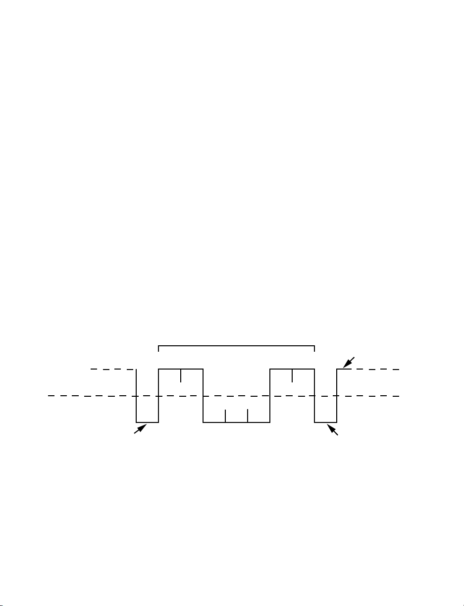
by a stop bit plus an optional parity bit, making train of 10 or 11 bits for each transmitted
character. The Figure 2.1 below shows transmission of the 7 bits of the ASCII lower case
“c” with start, stop and even parity bits.
• Baud Rate
The baud rate refers to the data transmission. It specifies the communication rate over
the bus. When a change in signal represents one data bit, baud rate is equal to bits per
second (bps). Standard baud rates for computers are 300, 600, 1200,2400, 4800, 9600
and 19200 baud.
Figure 2.1 Transmission of “c” with start, stop, and even parity bits.
• Communication Protocol
A data communication protocol defines the rules and structure of messages used by all
devices on a network for data exchange. This protocol also defines the orderly exchange
of messages, and the detection of errors. iLD Big Display controllers use i-SERIES and
MODBUS communication protocols.
4
7 - BIT CHARACTER
12345678
1
0
START BIT EVEN PARITY BIT
STOP BIT
Page 9
PART 3
HARDWARE
3.1 Communication Interfaces
Two communication interfaces are supported in the iLD Big Display devices: RS-232 and
RS-485. These standards define the electrical characteristics of a communication
network.
• The RS-232 standard (point-to-point) allows a single device to be connected to a PC.
The iLD Big Display devices operate with full-duplex RS-232 using three wires: a Rx receive wire, a Tx - transmit wire and a common ground wire. RS-232 cable length is
limited to 50 feet.
• The RS-485 standard (multipoint) allows one or more devices to be connected
(multi-dropped) using a two wire connection (half-duplex) +Rx / +Tx and -Rx / -Tx.
Use of RS-485 communications allows up to 32 “remote” devices to connect to the
“master” computer with cable length up to 4000 feet long.
• Both interfaces use standard RS-232/RS-485 voltage levels.
Although the RS-485 is commonly referred to as a “two wire” connection, the iLD
Big Display also provides a ground / return shield connection to use as a
common connection for EMI noise protection.
The Table 3.1 shows the differences between RS-232 and RS-485 communication
interfaces.
Table 3.1 Communication Interfaces
Data Transmission Characteristics RS232 RS485
Transmission Mode Single ended Differential
Electrical connections 3 wire 2 wire
Drivers per line 1 driver 32 drivers
Receivers per line 1 receiver 32 receiver
Maximum data rate 20k bits/s 10M bits/s
Maximum cable length 50 ft (15 meters) 4000 ft (1200 meters)
Changing between RS-232 and RS-485 is possible through the front panel
buttons (see Part 4 for details).
3.2 Wiring RS-232 Interface
Most PC’s provide an RS-232 port for digital communication. The RS-232 communication
uses three wire full-duplex system: a line for receiving data, a line for transmitting data
and a common line between the computer and device. Usually PCs use a 25 or 9 pin
connector.
Caution: Do not connect power to your instrument until you have completed all
serial interface connections. Failure to do so may result in injury.
5
Page 10
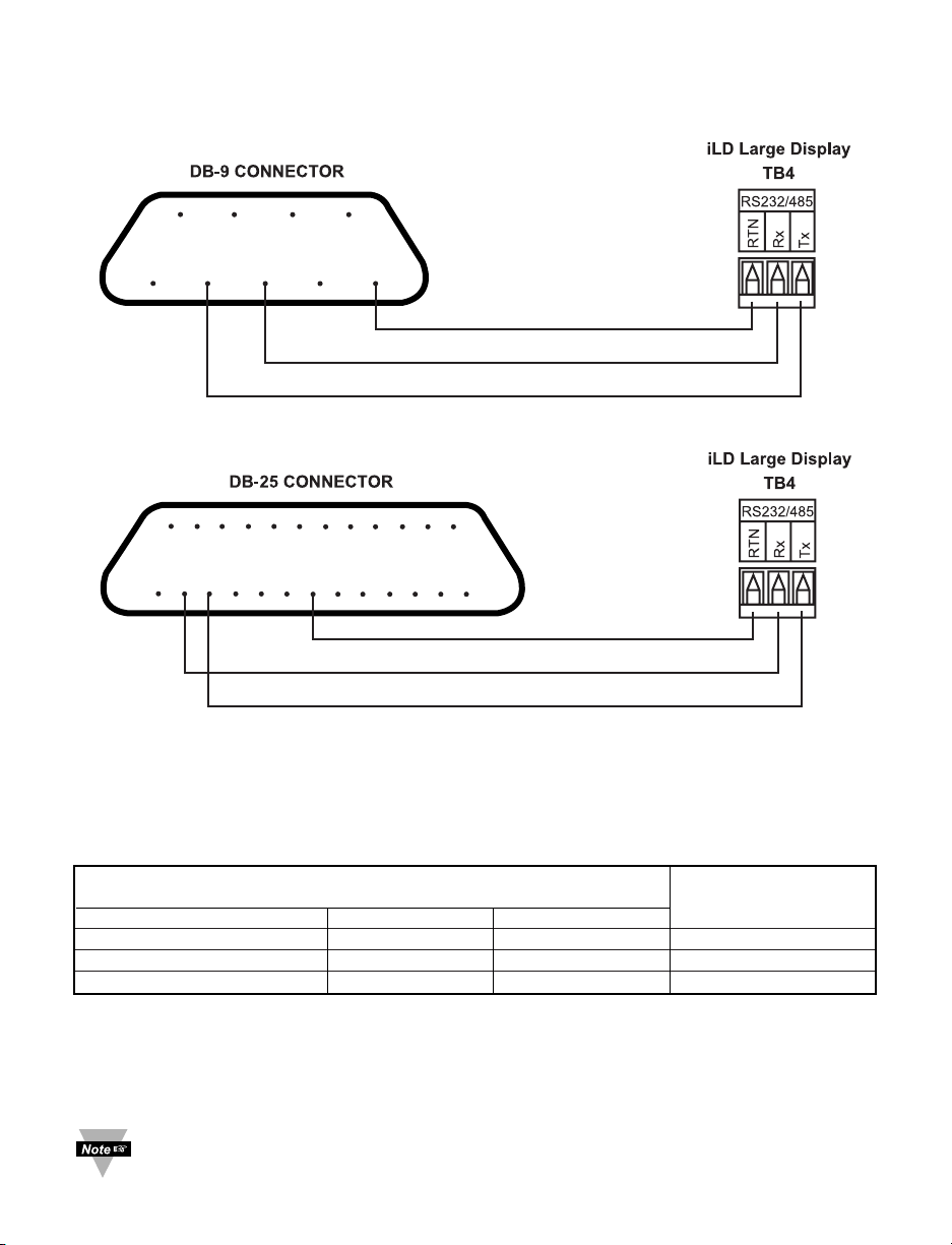
Figures 3.1 and 3.2 show the three-wire RS-232 connections between the host computer
using a 9-pin or 25-pin “D” connector and the iLD Big Display device.
Figure 3.1 Wiring between DB9 computer connector and RS-232 controller interface
Figure 3.2 Wiring between DB25 computer connector
and RS-232 controller interface
Table 3.2 shows the pin connection assignments between the RS-232 connector on the
meter and the 9-pin or 25-pin “D” connectors of your computer.
Table 3.2 Wiring RS-232 Interface
COMPUTER iLD Big Display
FUNCTION/LABEL
PIN FUNCTION DB9 DB25 TB4
Receive (Rx) 2 3 Transmit (Tx) 3
Transmit (Tx) 3 2 Receive (Rx) 2
Common ground 5 7 RTN 1
3.3 Wiring RS-485 Interface
RS-485 interface uses a two wire communication system (one for transmitting and one
for receiving) plus a common wire to connect to the shield of a cable. It is recommended
to use a shielded cable with one twisted pair.
Use of twisted pair and shield will significantly improve noise immunity.
6
789
6
2345
1
20 21 21 23 24 25
15 16 17 18
14
2 3 4 5
1
17
7 8 9 10 11 12 13
6
Page 11
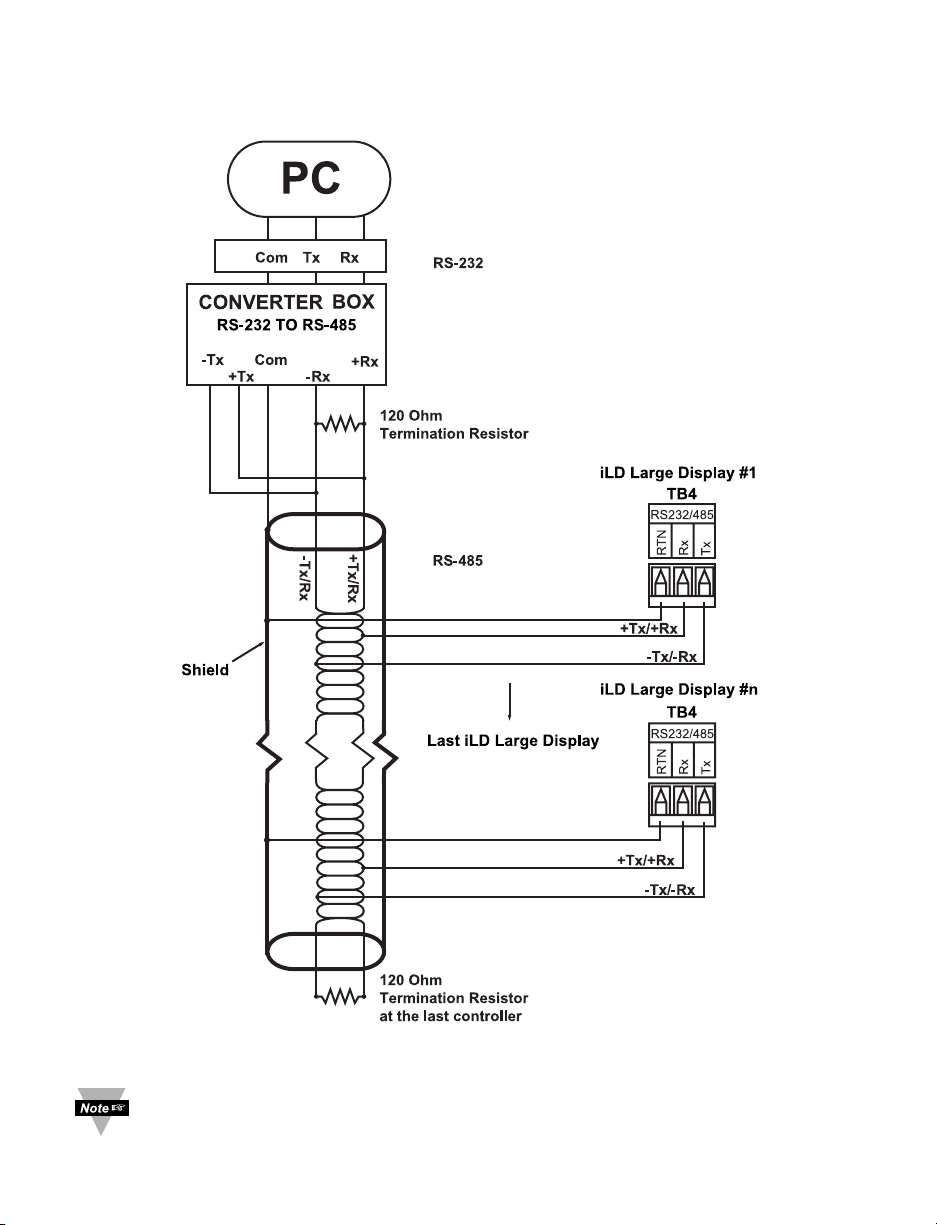
Figure 3.3 shows multipoint, half-duplex RS-485 interface connections for the iLD Big
Display.
Figure 3.3 Multipoint, Half-Duplex RS-485 wiring
Value of the termination resistor is not critical and depends on the cable
impedance.
7
Page 12
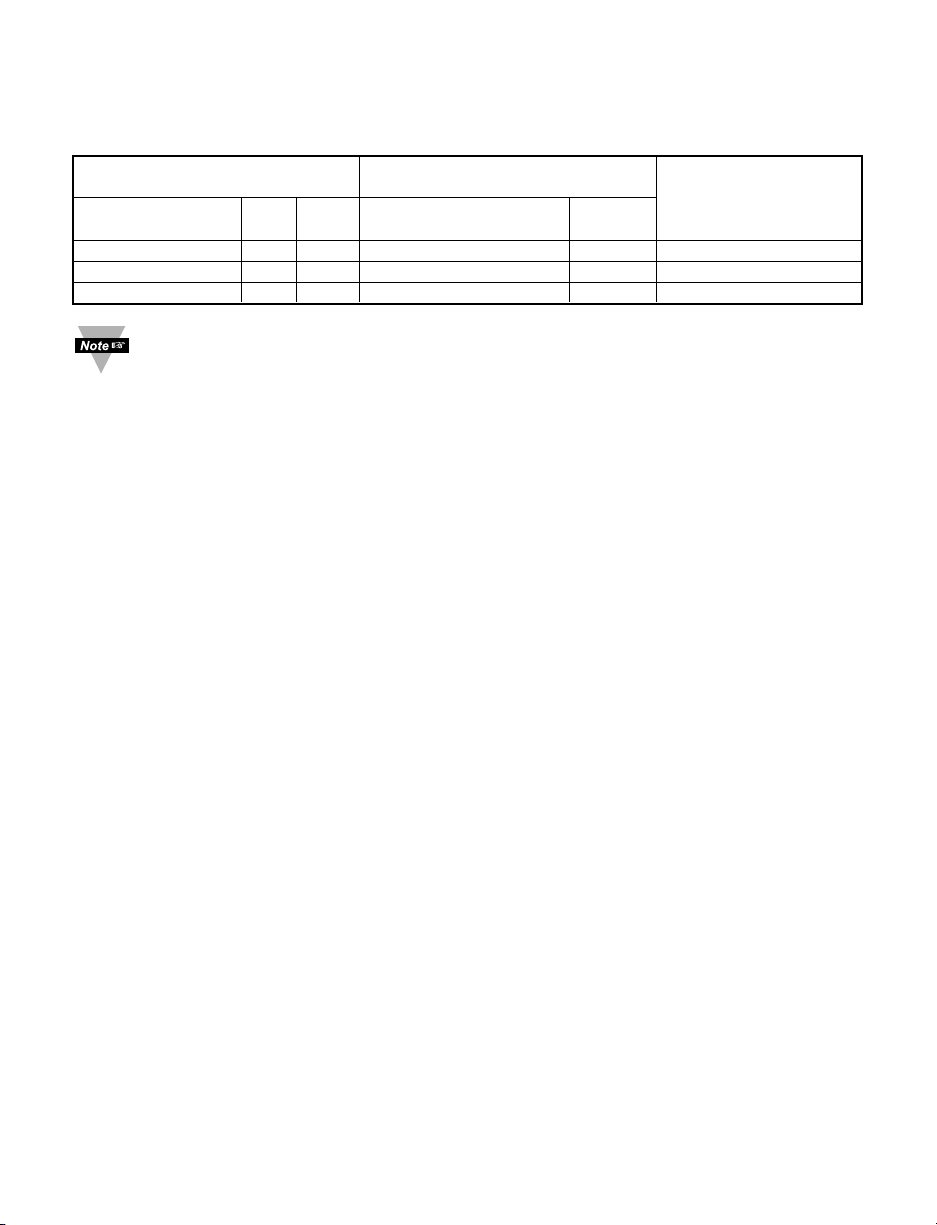
Table 3.3 shows RS-485 half-duplex hookup using a computer’s RS-232 interface, an
RS-485 interface converter, and an iLD Big Display controller.
Table 3.3 RS-485 Half-Duplex Hook-up
COMPUTER CONVERTER BOX iLD Big Display
FUNCTION/LABEL
PIN FUNCTION DB9 DB25 COMPUTER iLD TB4
SIDE SIDE
Rx/Tx 2 3 SEE CONVERTER’S -Rx/-Tx Tx 3
Rx/Tx 3 2 MANUFACTURING +Rx/+Tx Rx 2
Common ground 5 7 SPECIFICATION COM RTN 1
Communication Interfaces shown above are those which are used on iLD Big
Display devices. Other types of Communication Interfaces are not covered in this
chapter.
8
Page 13
PART 4
COMMUNICATION SETUP
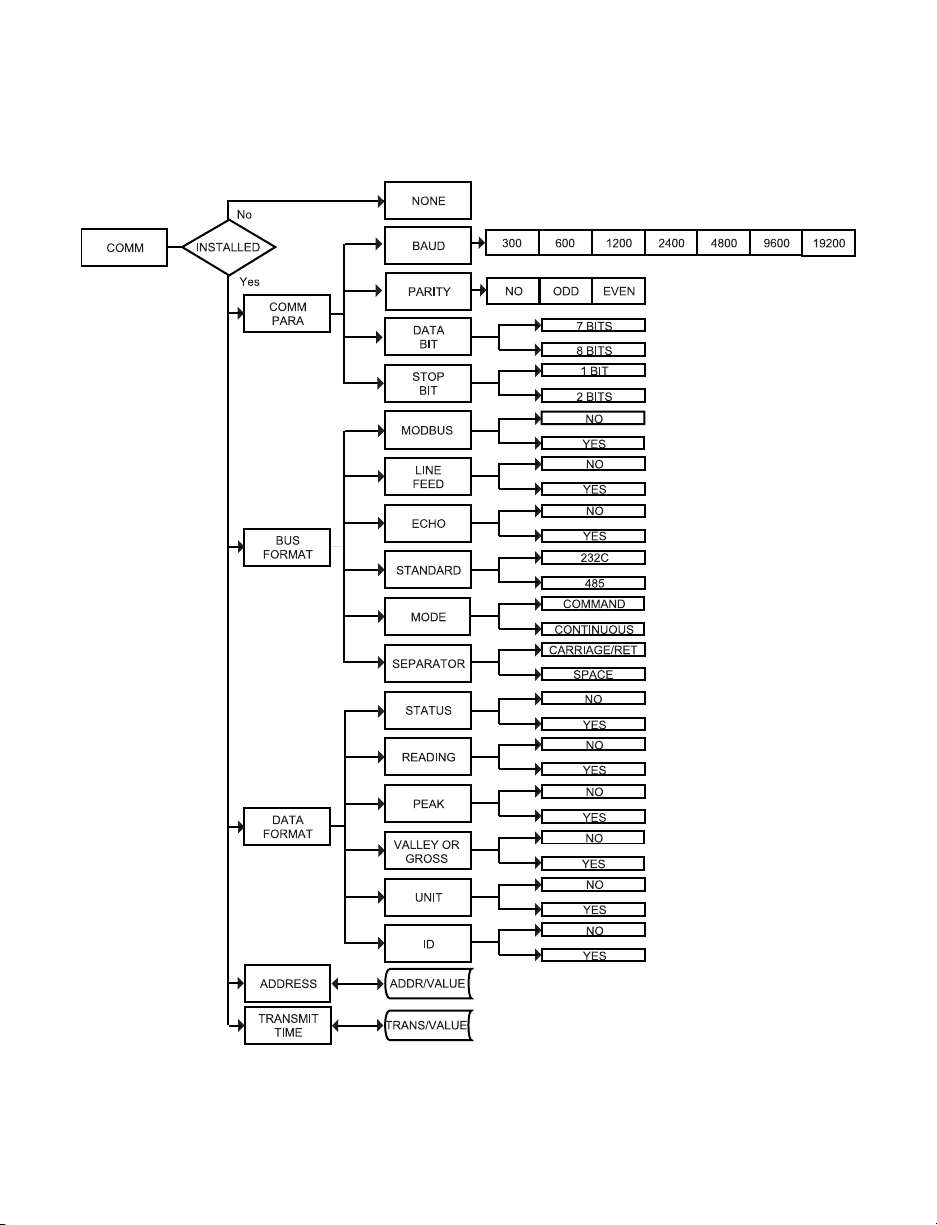
4.1 Flow Chart
Figure 4.1 Flow Chart for Communication Option
9
Page 14
4.2 Setup the iLD Big Display Device Through the Front Panel
You can setup your device by pressing the push buttons on the front panel.
ENTER COMMUNICATION OPTION MENU:
Press a 1) Press a until
CNFG
prompt appears.
Press d 2) Display advances to
INPT
Input Menu.
Press a 3) Press a, until display advances to
COMM
Communication Options Menu.
Press d 4) Display advances to
C.PAR
Communication Parameters Submenu.
a - Use a to advance/navigate through all Communication Menu items.
b - Press d to access the submenus from a top level of Communication Menu item.
Press d to store a submenu selection.
c
- Press bto scroll through “flashing” selection. When a numerical value is displayed,
press bto change a value of this parameter.
d - Press c to go back to a top level of Communication Menu item. Press c twice to
reset the device to Run mode.
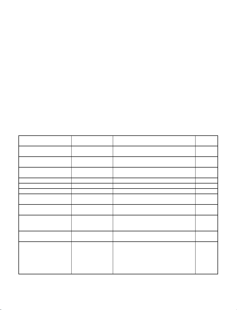
4.3 Abbreviations, Range, Default Setup
The Communication Menu Displays items using some abbreviations and compact
wording shown on Table 4.1.
Table 4.1 Abbreviations, Range, Default Setup
Display Function Range/ Definition Factory
(abbreviations) Default
C.PAR Communication
Parameter:
bAUd Baud rate 300, 600,1200, 2400
4800, 9600, 19200 9600
PRtY (odd_, EVEN, Parity Odd, Even, No odd
_No_)
dAtA (7.bit, 8.bit) Data bit 7 bit, 8 bit 7.bit
StOP (1.bit, 2.bit) Stop bit 1 bit, 2 bit 1.bit
bus.F Bus format:
M.bUS Modbus protocol Yes – Modbus protocol enabled
No – i-Series protocol enabled _No_
_LF_ Line feed Yes – print on every other line
No – print on every line _No_
ECHO Echo Yes – echo the command _YES
parameter
No – no echo
StNd (232C, 485_) Communication RS-232, RS-485 232C
Standard
ModE (CMd_, CoNt) Data Flow Mode Command – operate in Command CMd_
Mode (respond to valid command).
Continuous – operate in
Continuous mode (transmit
different measurement values
continuously on the bus).
10
Page 15
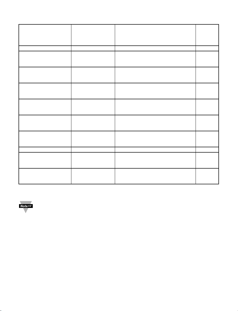
Abbreviations, Range, Default Setup Continued
SEPR (SPCE, _cR_) Data Separation Space – space inserted after each SPCE
Character piece of data.
Carriage Return – carriage return
inserted after each piece of data
dAt.F Data Format:
stAt Alarm Status Yes – enables the transmission of _No_
Alarms Value
No – disable
RdNG Reading Yes – enables the transmission _Yes
of Reading Value
No – disable
PEAk Peak Yes – enables the transmission _No_
of Peak Value
No – disable
VALY * Valley Yes – enables the transmission _No_
of Valley Value
No – disable
GROS ** Gross Yes – enables the transmission _No_
of Gross Value
No – disable
UNit Units Yes – enables the transmission _No_
of Units of Measurement
No – disable
AddR Multipoint Address 0000 to 0199 – Addressed Meter 0001
tR.tM Transmit Time 0000 to 5999 sec – transmission 0016
Interval Time Interval between consecutive
transmissions in Continuous Mode.
Recognition 20 Hex to 7F Hex (32 to 127 Dec) *
Character –see Table 2.1, except “^”, “A”,
“E”
* - For Temperature/Process instrument only
** - For Process/Strain Gauge instrument only
1. There is no Continuous Mode, when the device is configured to use the
RS-485 interface standard.
2. The Multipoint Address will be included in the transmission data if RS-485
standard has been selected in the menu items.
3. Transmit time is available only when the device has been configured for
Continuous Mode and RS-232 Standard.
4. If the meter is in point-to-point Continuous Mode, it ignores any transmitted
commands except Crtl S, which will stop transmission.
11
Page 16

Communications Parameters Submenu
Allows the user to adjust Serial Communications settings of the device. When
connecting an instrument to a computer or other device, the Communication Parameters
must match. Generally the default settings shown in Table 4.1 should be utilized.
Bus Format Submenu
Determines communications standards and command/data formats for transferring
information into and out of the device via the Serial Communications Bus.
Bus Format submenus essentially determine how and when data can be accessed via
the Serial Communications Port of the device.
Data Format Submenu
Preformatted data can be sent automatically or upon request from the device. Use the
Data Format Submenus to determine what data will be sent in this preformatted data
string. At least one of the Data Format suboptions must be enabled to send output data
to the Serial Bus.
Recognition Character
A selectable symbol transmitted as the first character of each message from the
computer, which is used for message security: the meter ignores messages without this
symbol.
12
Page 17
PART 5
i-SERIES PROTOCOL
To Enable the i-Series Protocol, set the Modbus menu item to “No” in the Bus
Format Submenu of the Communication Menu. Refer to Section 5.7.11.
A Data Communication Protocol defines the rules and structure of messages used by all
devices on a network for data exchange. A typical transaction will consist of a request to
send from the “master” followed by the response from the “slave”.
5.1 Command Structure
The device can be commanded to “Read”, i.e., to transmit (send) data from either the
nonvolatile memory (EEPROM) or from the volatile working memory (RAM).
The device can also be commanded to “Write”, i.e., store new values for data processing
or control.
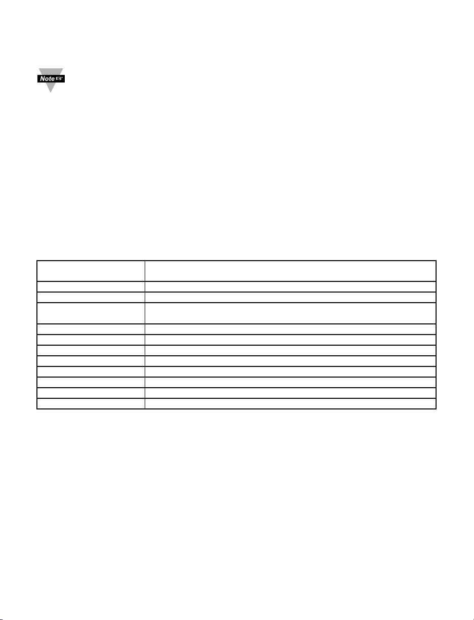
There are different command types associated in communicating with your meter shown
in Table 5.1, which shows the Command Prefix Letters (Command Classes).
Table 5.1 Command Prefix Letters
COMMAND PREFIX
(COMMAND CLASS)
MEANING
^AE Special read, Communication parameters
P (Put) Write HEX data into RAM
W (Write) Write HEX data into EEPROM. 1,000,000 writes to EEPROM
is guaranteed!
G (Get) Read HEX data from RAM
R (Read) Read HEX data from EEPROM
U Read status byte
V Read measurement data string in Decimal format
X Read measurement data values in Decimal format
D Disable
E Enable
Z Reset
13
Page 18
5.2 Command Formats
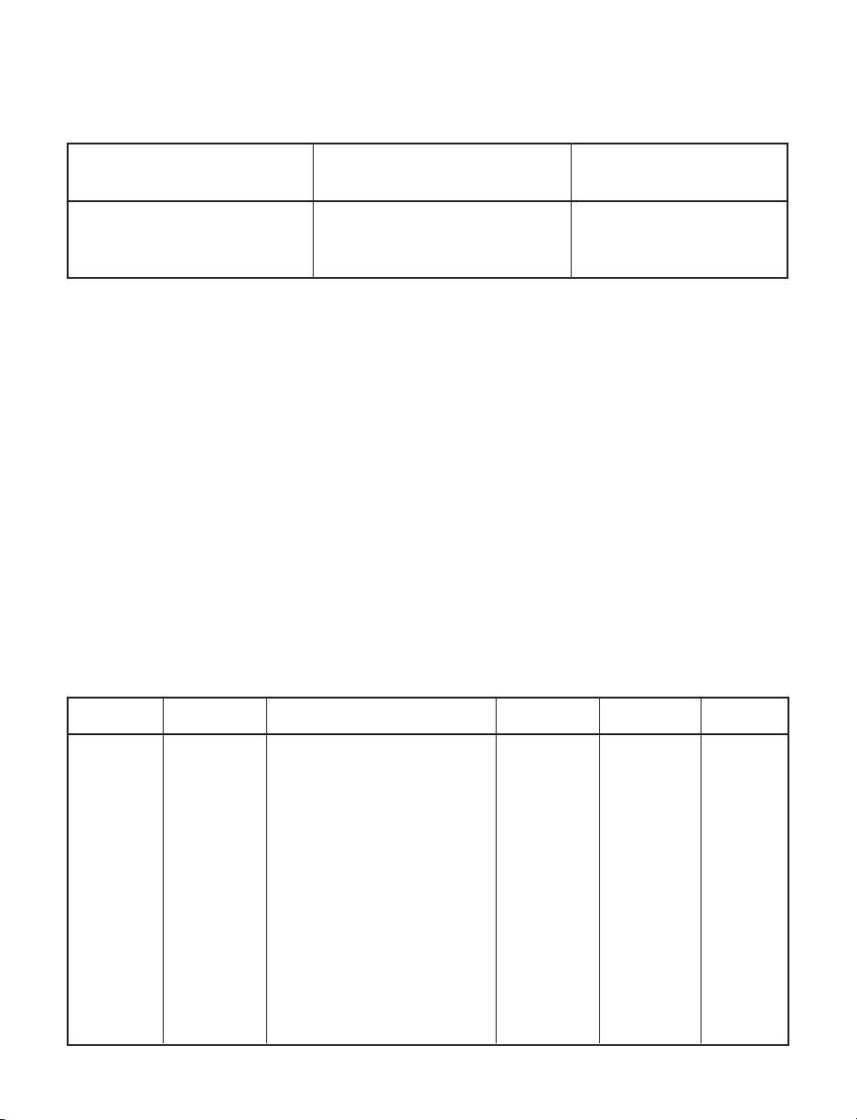
Table 5.2 shows the command formats for iLD Big Display devices.
Table 5.2 Command Formats
For “P” and “W” Command For “G” and “R” Command For “X”, “V”, “U”, “D”,
classes: classes: “E”, and”Z” Command
classes:
Point-to-point mode Point-to-point mode Point-to-point mode
* ccc<data><cr> * ccc <cr> * ccc <cr>
Multipoint mode Multipoint mode Multipoint mode
* nnccc [<data>]<cr> * nnccc <cr> * nnccc <cr>
Where:
“*” is the selected Recognition Character. You may select any ASCII table symbol from
“!” (HEX address “21”) to the right-hand brace (HEX “7D”) except for the caret “^”, “A”,
“E”, which are reserved for bus format request.
“ccc” stands for the hex-ASCII Command Class letter (one of eleven given in Table 5.1),
followed by the two hex-ASCII Command Suffix characters identifying the meter data,
features or menu items to which the command is directed (given in Table 5.3).
“<data>” is the string of characters containing the variable information the computer is
sending to the meter. These data (whether BCD or binary) are encoded into hex-ASCII
characters, two characters to the byte. Square brackets (indicating optional status)
enclose this string, since some commands contain no data.
“<nn>” are the two ASCII characters for the device Bus Address of RS-485
communication . Use values from “00” to hex “C7” (199 decimal).
Table 5.3 and 5.4 shows the command letters and suffix for iLD Big Display devices.
Table 5.3 Command Letters and Suffix for Temperature/Process and Process/Strain Gauge
Instruments
Command Command Function Command # Of Default
Index Bytes Characters Value
RW 01 SP1 3 6 200000
RW 02 SP2 3 6 200000
GPRW 03 RDGOFF 3 6 200000
RW 04 ANLOFF 3 6 400000
RW 05 ID 2 4 0003
-06 N/A - --
RW 07 INPUT 1 2 04
GPRW 08 RDGCNF 1 2 4A
RW 09 AL1CNFG 1 2 00
RW 0A AL2CNFG 1 2 00
RW 0B LOOP BREAK TIME 2 4 003B
RW 0C OUT1CNF 1 2 00
RW 0D OUT2CNF 1 2 60
RW 0E RAMPTIME 2 4 0000
14
Page 19

Command Letters and Suffixes Continued
Command Command Function Command # Of Default
Index Bytes Characters Value
RW 0F ANLSCL 3 6 9186A0
RW 10 COMM.PARAMETERS 1 2 0D
RW 11 COLOR 1 2 09
RW 12 AL1LO 3 6 A003E8
RW 13 AL1HI 3 6 200FA0
GPRW 14 RDGSCL 3 6 100001
RW 15 AL2LO 3 6 A003E8
RW 16 AL2HI 3 6 200FA0
GPRW 17 PB1/DEAD BAND 2 4 00C8
GPRW 18 RESET 1 2 4 00B4
GPRW 19 RATE 1 2 4 0000
GPRW 1A CYCLE 1 1 2 07
-1B N/A - - -
GPRW 1C PB2/DEAD BAND 2 4 00C8
GPRW 1D CYCLE 2 1 2 07
RW 1E SOAK TIME 2 4 0000
RW 1F BUS FORMAT 1 2 14
GPRW 20 DATA FORMAT 1 2 02
RW 21 ADDRESS 1 2 01
RW 22 Transit Time Interval 2 4 0010
-23 N/A - --
RW 24 Miscellaneous 1 2 00
RW 25 C.J. OFFSET ADJ. 3 6 200000
RW 26 Recognition Character 1 2 2A
RW 27 %LOW 1 2 00
RW 28 %HI 1 2 63
D 01 DISABLE ALARM 1 0 0 D 02 DISABLE ALARM 2 0 0 D 03 STANDBY 0 0 D 04 DISABLE SELF 0 0 E 01 ENABLE ALARM 1 0 0 E 02 ENABLE ALARM 1 0 0 E 03 DISABLE STANDBY 0 0 E 04 ENABLE SELF 0 0 X 01 SEND READING 0 0 X 02 SEND PEAK READING 0 0 X 03 SEND VALLEY READING 0 0 U 01 SEND ALARM STATUS 0 0 U 03 SEND SW VERSION 0 0 V 01 SEND DATA STRING 0 0 Z 02 HARD RESET 0 0 -
15
Page 20

Table 5.4 Command Letters and Suffix for Process/Strain Gauge Instrument with
10 Linearization Points
Command Command Function Command # Of Default
Index Bytes Characters Value
RW 01 SP1 3 6 200000
RW 02 SP2 3 6 200000
GPRW 03 RDGOFF 3 6 200000
RW 04 ANLOFF 3 6 400000
RW 05 ID 2 4 0003
-06 N/A - --
RW 07 INPUT 1 2 04
GPRW 08 RDGCNF 1 2 4A
RW 09 AL1CNFG 1 2 00
RW 0A AL2CNFG 1 2 00
RW 0B LOOP BREAK TIME 2 4 003B
RW 0C OUT1CNF 1 2 00
RW 0D OUT2CNF 1 2 60
RW 0E RAMPTIME 2 4 0000
RW 0F ANLSCL 3 6 9186A0
RW 10 COMM.PARAMETERS 1 2 0D
RW 11 COLOR 1 2 09
RW 12 AL1LO 3 6 A003E8
RW 13 AL1HI 3 6 200FA0
GPRW 14 RDGSCL 3 6 100001
RW 15 AL2LO 3 6 A003E8
RW 16 AL2HI 3 6 200FA0
GPRW 17 PB1/DEAD BAND 2 4 00C8
GPRW 18 RESET 1 2 4 00B4
GPRW 19 RATE 1 2 4 0000
GPRW 1A CYCLE 1 1 2 07
-1B N/A - - -
GPRW 1C PB2/DEAD BAND 2 4 00C8
GPRW 1D CYCLE 2 1 2 07
RW 1E SOAK TIME 2 4 0000
RW 1F BUS FORMAT 1 2 14
GPRW 20 DATA FORMAT 1 2 02
RW 21 ADDRESS 1 2 01
RW 22 Transit Time Interval 2 4 0010
-23 N/A - - -
RW 24 Miscellaneous 1 2 00
RW 25 C.J. OFFSET ADJ. 3 6 200000
RW 26 Recognition Character 1 2 2A
RW 27 %LOW 1 2 00
RW 28 %HI 1 2 63
16
Page 21

17
Command Letters and Suffixes Continued
Command Command Function Command # Of Default
Index Bytes Characters Value
RW 2B INPUT FOR SCALE 1 3 6 RW 2C INPUT FOR SCALE 2 3 6 RW 2D INPUT FOR SCALE 3 3 6 RW 2E INPUT FOR SCALE 4 3 6 RW 2F INPUT FOR SCALE 5 3 6 RW 29 Linearization Points 1 2 00
RW 30 INPUT FOR SCALE 6 3 6 RW 31 INPUT FOR SCALE 7 3 6 RW 32 INPUT FOR SCALE 8 3 6 RW 33 INPUT FOR SCALE 9 3 6 RW 34 RDGSCL1/SCALE 1 3 6 RW 35 RDGSCL2/SCALE 2 3 6 RW 36 RDGSCL3/SCALE 3 3 6 RW 37 RDGSCL4/SCALE 4 3 6 RW 38 RDGSCL5/SCALE 5 3 6 RW 39 RDGSCL6/SCALE 6 3 6 RW 3A RDGSCL7/SCALE 7 3 6 RW 3B RDGSCL8/SCALE 8 3 6 RW 3C RDGSCL9/SCALE 9 3 6 RW 3D RDGOFF1/OFFSET 1 3 6 RW 3E RDGOFF2/OFFSET 2 3 6 RW 3F RDGOFF3/OFFSET 3 3 6 RW 40 RDGOFF4/OFFSET 4 3 6 RW 41 RDGOFF5/OFFSET 5 3 6 RW 42 RDGOFF6/OFFSET 6 3 6 RW 43 RDGOFF7/OFFSET 7 3 6 RW 44 RDGOFF8/OFFSET 8 3 6 RW 45 RDGOFF9/OFFSET 9 3 6 -
D 01 DISABLE ALARM 1 0 0 D 02 DISABLE ALARM 2 0 0 D 03 STANDBY 0 0 D 04 DISABLE SELF 0 0 E 01 ENABLE ALARM 1 0 0 E 02 ENABLE ALARM 1 0 0 E 03 DISABLE STANDBY 0 0 E 04 ENABLE SELF 0 0 X 01 SEND READING 0 0 X 02 SEND PEAK READING 0 0 X 03 SEND VALLEY READING 0 0 U 01 SEND ALARM STATUS 0 0 U 03 SEND SW VERSION 0 0 V 01 SEND DATA STRING 0 0 Z 02 HARD RESET 0 0 -
Page 22

After modifying any settings with the use of the W prefix commands, a Hard Reset
command should be sent in order to load the changes into Volatile memory.
Examples:
1. To reset the controller, send *Z02 (Table 5.3 & 5.4)
2. To read Setpoint 1, send *R01 (Table 5.3 & 5.4)
3. To change Setpoint 1 to 100.0, send *W012003E8 (see explanation below)
Description: SETPOINT.23~0 means 3 bytes x 8 bit positions
(2 hex. character in each byte)
Where 23~0 are 3 x 8 = 24 Binary bit positions
SETPOINT.23 = SETPOINT.22~20 = SETPOINT.19~0 =
0 = positive sign 000 – Not Allowed Setpoint data
1 = negative sign 001 – Decimal Point 1 (FFFF.)
010 – Decimal Point 2 (FFF.F)
011 – Decimal Point 3*(FF.FF)
101 – Decimal Point 4*(F.FFF)
*Process only
For 100.0: Positive sign = 0, Decimal Point 2 = 010 Bin, Setpoint data 1000 = 3E8 Hex =
=00 1111101000 Bin
The command data = 0010 0000 0000 0011 1110 1000 Bin = 2003E8 Hex.
2 0 0 3 E 8 Hex
Send *W01 20 03E8
where:
*W01 - *<ccc> - write to Setpoint 1 (Table 5.2)
2003E8 - <data> - Setpoint data in hexadecimal format including sign and decimal
point (Table 5.2)
No spaces are allowed in the data string. The spaces shown on the above
example for illustration purposes only.
Decimal Point position for TC/RTD = 1 or 2, for PROCESS = 1, 2, 3, or 4
Decimal Point position for Set Point should be the same as Decimal Point
position set for process value and can not be overwritten by SETPOINT
command (see RDGCNG command, described in 5.7.2).
4. To change Setpoint 1 to –100.0, send *W01A003E8 (see explanation below)
For (–100.0): Negative sign = 1, Decimal Point 2 = 010 Bin, Setpoint data
1000=3E8 Hex = 001111101000 Bin
The command data = 1010 0000 0000 0011 1110 1000 Bin = A003E8 Hex
A 0 0 3 E 8 Hex
Send *W01A003E8
5. To send the same as above for RS-485 with transmit address 01, the command is
Send *01W01A003E8.
18
Page 23

5.3 Response Format
Table 5.5 and 5.6 show response format with ECHO and without ECHO Mode selection.
Table 5.5 Echo Mode
For “P” and “W” For “G” and “R” For “X”,”V” and “U”
For “D”, “E” and “Z”
Command Command Command Command
classes: classes: classes: classes:
Point-to-point Point-to-point Point-to-point Point-to-point
mode mode mode mode
ccc<cr> ccc<data> <cr> ccc<value><cr> ccc<cr>
Multipoint mode Multipoint mode Multipoint mode Multipoint mode
nnccc <cr> nnccc<data> <cr> nnccc<value><cr> nnccc<cr>
Examples:
1. Sent: *W012003E8 (Change Setpoint 1 to 100.0- see example above)
Response: W01
2. Sent *R01 (Read Setpoint 1, which set to 100.0)
Response: R012003E8
3. Sent: *X01 (Controller reads 75.4 F and Units set to “No”)
Response: X01075.4
4. Sent: *E02 (Enable Alarm 2)
Response: E02
Table 5.6 No ECHO Mode
For “P” and “W” For “G” and “R” For “X”,”V” and “U”
For “D”, “E” and “Z”
Command Command Command Command
classes: classes: classes: classes:
Point-to-point Point-to-point Point-to-point Point-to-point
mode mode mode mode
No Response <data> <cr> <value><cr> No Response
Multipoint mode Multipoint mode Multipoint mode Multipoint mode
No Response <data> <cr> <value><cr> No Response
Examples:
1. Sent: *W012003E8 (Change Setpoint 1 to 100.0 - see example above)
Response: No Response
2. Sent *R01 (Read Setpoint 1, which set to 100.0)
Response 2003E8
3. Sent: *X01 (Controller reads 75.4 F and Units set to “No”)
Response: 075.4
4. Sent: *E02 (Enable Alarm 2)
Response: No Response
<data> in Hexadecimal format, except “U” command class, <value> reading in
Decimal format
19
Page 24
20
5.4 Error Message
The instrument is capable of detecting different errors during the Communication process
and will transmit an indicating message as shown in Table 5.7 to the host computer.
Table 5.7 Error Message
ERROR MESSAGE CODE
1 Command Error ?43
2 Format Error ?46
3 Parity Error ?50
4 Serial Device Address Error ?56
Where:
1. COMMAND ERROR occurs when:
a. Command prefix letter is not valid.
b. Command suffix is not valid.
2. FORMAT ERROR occurs when:
a. Length of message is either shorter or longer than it should be.
b. Any characters other than “0 – F” used for hexadecimal values.
3. PARITY ERROR occurs when transmitted parity does not match with parity set on
the receiver.
4. Serial Device Address Error occurs if the new value is larger than 199 decimal.
1. The iLD Big Display device will not respond to a command if the command‘s
recognition character does not match the meter’s recognition character.
2. When in Multipoint mode, the device will not respond to the command if the
addresses do not match.
3. If the device is in the Menu or Setpoint Mode and receives any transmitted
data, it quits that routine, displays
COMM
for up to 2 seconds, completes its
Communication job, and then resets the device, i.e., hard reset.
5.5 Alarm Status Characters
The meter, upon receiving the U01 Command, will transmit the alarm status characters.
Table 5.8 shows the transmitted character for each of the possible setpoint/alarm states.
Table 5.8 Alarm Status Characters
CHARACTER Alarm1 Alarm2
@ OFF OFF
A ON OFF
B OFF ON
CONON
Page 25

5.6 Examples of Transmitted Data
1. The following menu items have been selected:
Standard – RS-232, Mode – Continuous, Linefeed – No, Separation – Space, Status - No
Echo – No, Reading – Yes, Valley – Yes, Peak – Yes, Unit of measurement – Yes
Assume that instrument has the following data:
Reading value = 74.2°F, Peak value = 75.1°F, Valley value = 73.2°F
Alarm 1 – OFF, Alarm 2 - OFF
Instrument will transmit: 74.2 75.1 73.2 F
2. The following menu items have been changed: Separation – Carriage Return
Instrument will transmit: 74.2
75.1
73.2 F
3. The following menu items have been changed: Alarm Status – Yes
Instrument will transmit: @
74.1
75.1
73.2 F
4. The following menu items have been changed: ECHO – Yes, Alarm 1 - ON
Instrument will transmit: V01
A
74.2
75.1
73.2 F
21
Page 26
5.7 Command Formats
The following conditions are assumed in the examples in this section.
1. The recognition character is the asterisk (*).
2. The meter uses the RS-232 interface standard (point-to-point communication).
3. When the “W” command is given, a reset is necessary to initiate the command.
4. Each byte consist of 8 bits.
5. “ “ (blank) in bit pattern information means the bit is not applicable to that parameter.
Note that all ranges have been given decimal numbers. To make a data
command, the decimal numbers are converted into a hex numbers and then the
digits of that hex number are encoded into their equivalent ASCII values.
5.7.1 Input Type (Command Index 07)
Description: INPUT.76543210 means 8 bit positions of the Command Data.
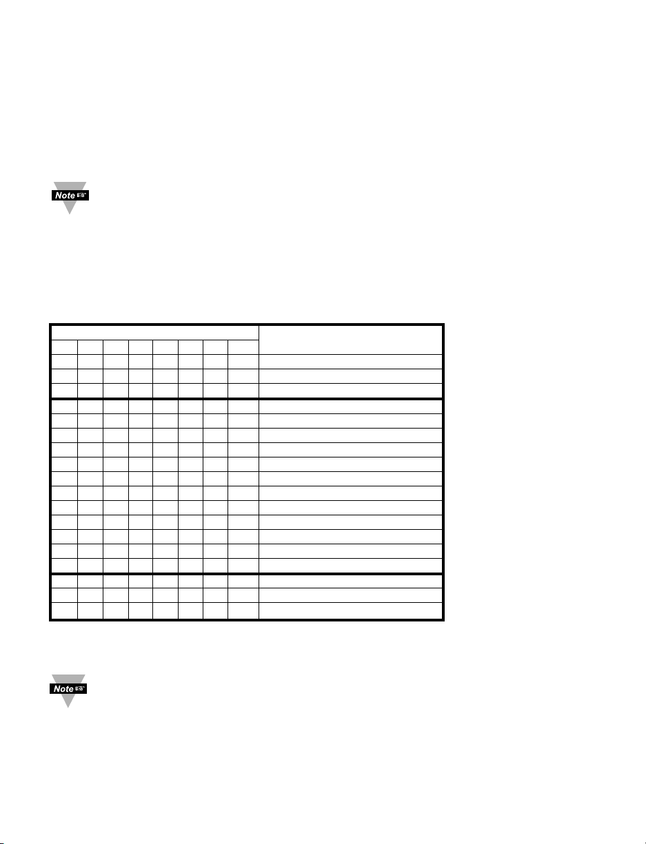
5.7.1.1 Input Type Format for Temperature/Process Instrument
BIT POSITION INPUT CLASS, RANGE
7 6 5 4 3 2 1 0 OR TYPE
0 0 TC (Thermocouple)
01 RTD
1 0 PROCESS
TC/ RTD/ PROCESS
0000 J/ 392.2/ 0-100 mV
0001 K/ 392.3/ 0-1 V
0010 T/ 392.4/ 0-10 V
0011 E/ 385.2/ 0-20 mA
0100 N
0101 DIN-J/ 385.4
0110 R
0111 S
1000 B/ xx/ xx
1001 C/ xx/ xx
1100 xx/ 385.3/ xx
0 0 100 ohm RTD
0 1 500 ohm RTD
1 0 1000 ohm RTD
Example: Set RTD, 4 wire, .0392 Curve, 100 ohms.
The command data is 00001001 Bin = 09HEX. Send: *W0709
Send a Read command first to determine the bits, which are not specified for
some positions (TC and Process for positions 7,6 above).
22
Page 27
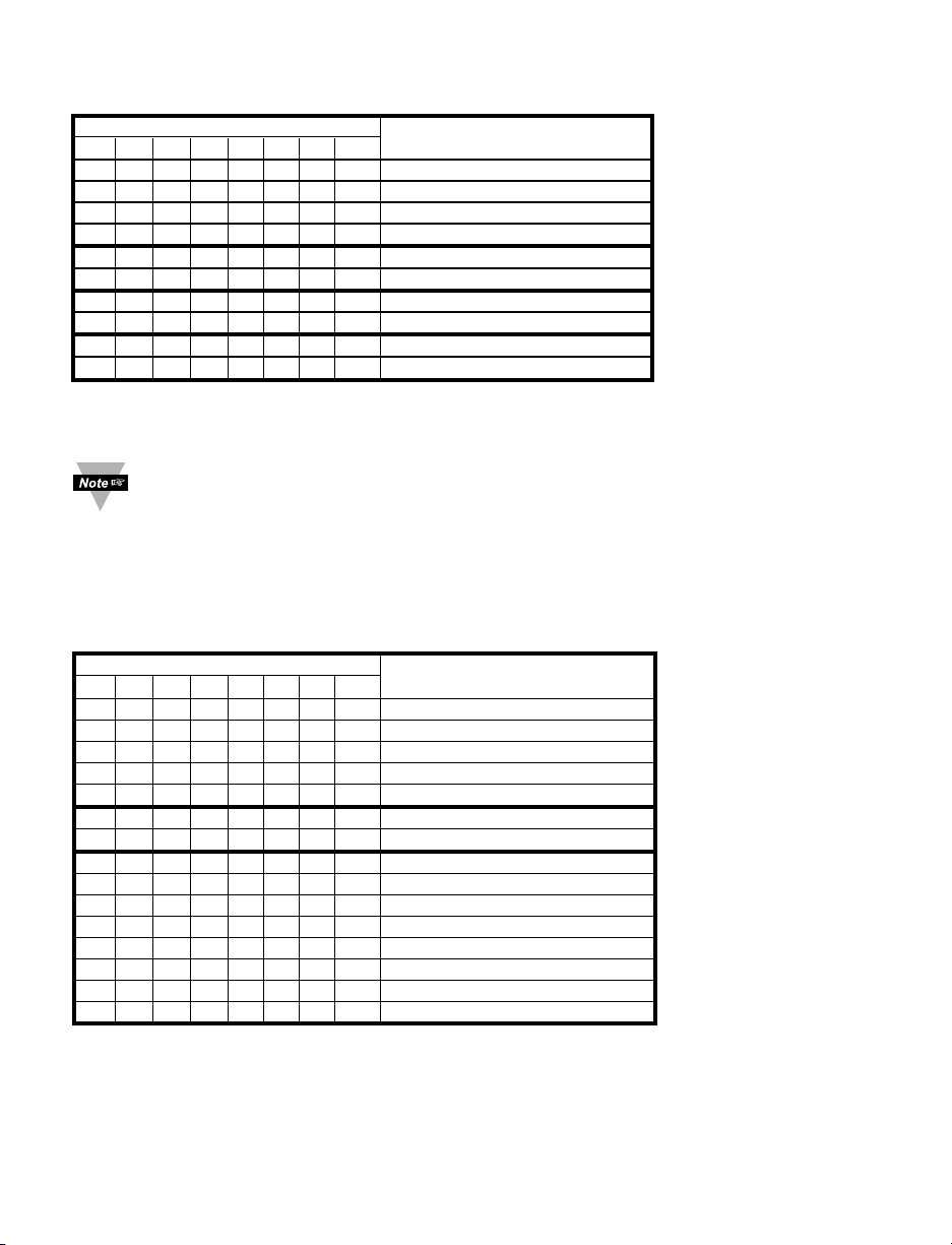
5.7.1.2 Input Type Format for Process/Strain Gauge Instrument
BIT POSITION INPUT CLASS, RANGE
7654321 0 OR TYPE
0 0 Voltage 0 ~ 100 mV
0 1 Voltage 0 ~ 1 V
1 0 Voltage 0 ~ 10 V
1 1 Voltage 0 ~ 20 mA
0 Ratio Disable
1 Ratio Enable
0 Low Resolution
1 High Resolution
0 Peak Value
1 Gross Value
Example: Set Voltage 0 ~ 100 mV, Ratio Enabled, Low Resolution, Gross Value
The command data is 00010100 Bin = 14HEX. Send: *W0714
Send a Read command first to determine the bits, which are not specified for
some positions (positions 7,6 and 5 above).
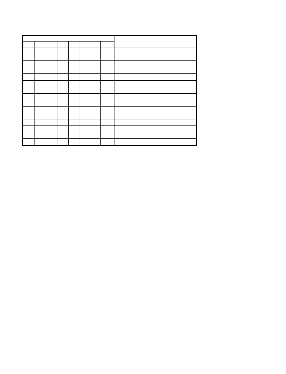
5.7.2 Reading Configuration: (Command Index 08)
Description: RDGCNG.76543210 means 8 bit positions of the Command Data.
5.7.2.1 Reading Configuration Format for Temperature/Process Instrument
BIT NUMBER FUNCTION
76543210
0 0 0 Not Allowed
0 0 1 Decimal Point 1 (FFFF)
0 1 0 Decimal Point 2 (FFF.F)
0 1 1 Decimal Point 3 (FF.FF)
1 0 0 Decimal Point 4 (F.FFF)
0°C
1°F
0 0 0 Filter Constant 1
0 0 1 Filter Constant 2
0 1 0 Filter Constant 4
0 1 1 Filter Constant 8
1 0 0 Filter Constant 16
1 0 1 Filter Constant 32
1 1 0 Filter Constant 64
1 1 1 Filter Constant 128
Example: Set Decimal point 1, ºC, Filter constant 16.
The command data is 10000001Bin = 81Hex. Send: *W0881
23
Page 28
24
5.7.2.2 Reading Configuration Format for Process/Strain Gauge Instrument
BIT NUMBER FUNCTION
76543210
0 0 0 Not Allowed
0 0 1 Decimal Point 1 (FFFF)
0 1 0 Decimal Point 2 (FFF.F)
0 1 1 Decimal Point 3 (FF.FF)
1 0 0 Decimal Point 4 (F.FFF)
0 Load (On line Cal) Disable
1 Load Enable
0 0 0 Filter Constant 1
0 0 1 Filter Constant 2
0 1 0 Filter Constant 4
0 1 1 Filter Constant 8
1 0 0 Filter Constant 16
1 0 1 Filter Constant 32
1 1 0 Filter Constant 64
1 1 1 Filter Constant 128
Example: Set Decimal point 2, Load Enable, Filter constant 4.
The command data is 01010010 Bin = 81Hex. Send: *W084A
5.7.3 Linearization Point (Command Index 29)
The data for number of Linearization Points (number of Scales and Offsets) has offset of -2.
Example: Linearization Points 2 (Scale/Offset number 1 is active for the entire range)
Send: *W2900
Example: Linearization Points 10 (All 9 Scale/Offset are active)
Send: *W2908
Page 29
25
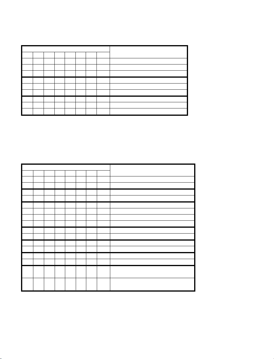
5.7.4 Color Display (Command Index 11)
Description: CLR.76543210 means 8 bit positions of the Command Data.
BIT NUMBER FUNCTION
76543210
0 0 Alarm 2 Color AMBER
0 1 Alarm 2 Color GREEN
1 0 Alarm 2 Color RED
0 0 Alarm 1 Color AMBER
0 1 Alarm 1 Color GREEN
1 0 Alarm 1 Color RED
0 0 Normal Color AMBER
0 1 Normal Color GREEN
1 0 Normal Color RED
Example: Set Normal color green, Alarm 1 color red, Alarm 2 color amber
The command data is 00001001Bin = 09Hex. Send *W1109
5.7.5 Alarm 1 Configuration (Command Index 09)
Description: ALR1CNG.76543210 means 8 bit positions of the Command Data.
BIT NUMBER FUNCTION
76543210
0 Alarm 1 at Power On Disable
1 Alarm 1 at Power On Enable
0 Loop Break Time Disable
1 Loop Break Time Enable
0 0 Active Above
0 1 Active Below
1 0 Active Hi/Lo
1 1 Active Band (Deviation only)
0 Normally Open
1 Normally Closed
0 Unlatch
1 Latch
0 Absolute
1 Deviation
0 Disable Alarm 1 /
Retransmission
1 Enable Alarm 1 /
Retransmission
Example:Set Alarm 1 Enable, Deviation, Unlatch, N.C., Band, Loop Disable, Alarm at
Power On Enable. The command data is 10111011Bin = BBHex.
Send: *W09BB
Page 30
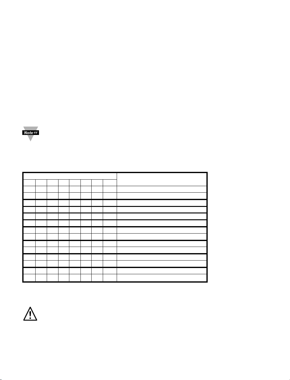
5.7.6 Alarm 1 Low (Command Index 12)
Description: AL1LO.23~0 means 3 bytes x 8 bit positions of the Alarm Low Data
AL1LO.23 = AL1LO.22~20 = AL1LO.19~0 =
0 = positive sign 000 – Not Allowed Setpoint data
1 = negative sign 001 – Decimal Point 1 (FFFF.)
010 – Decimal Point 2 (FFF.F)
011 – Decimal Point 3*(FF.FF)
101 – Decimal Point 4*(F.FFF)
*Process only
Example:Set Alarm 1 Low value to -50.0
The command data is 101000000000000111110100Bin = A001F4Hex.
Send: *W12A001F4
To set the Decimal Point for proper position see command format for RDGCNF
(command index 08).
5.7.7 Alarm 2 Configuration (Command Index 0A)
Description: ALR2CNG.76543210 means 8 bit positions of the Command Data.
BIT NUMBER FUNCTION
76543210
0 Voltage Retransmission
1 Current Retransmission
0 0 Active Above
0 1 Active Below
1 0 Active Hi/Lo
1 1 Active Band (Deviation only)
0 Normally Open
1 Normally Closed
0 Unlatch
1 Latch
0 Absolute
1 Deviation
0 Disable
1 Enable
Example: Set Alarm 2 Enable, Absolute, Latch, N.O.,Above, Current Retransmission.
The command data is 10000101 Bin = 85Hex. Send: *W0A85
Warning: If you change the “0A” to “00” on units with Isolated Analog Output it
will disable the Alarm 2 menu.
26
Page 31
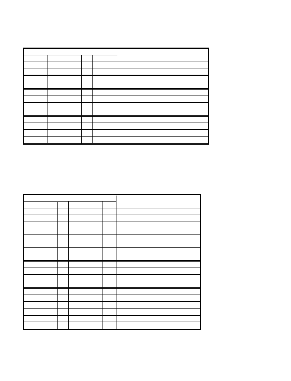
5.7.8 Output 1 Configuration (Command Index 0C)
Description: OUT1CNG.76543210 means 8 bit positions of the Command Data.
BIT NUMBER FUNCTION
76543210
0 Auto Tune PID Stop
1 Auto Tune PID Start
0 Anti Wind Up Disable
1 Anti Wind Up Enable
0 Auto PID Disable
1 Auto PID Enable
0 Reverse
1 Direct
0 Analog Proportional 0 – 20 mA
1 Analog proportional 4 – 20 mA
0 Time Proportional On/Off
1 Time Proportional PID
Example: Set PID, Direct, Auto PID Enable, Anti Integral Enable, Auto PID Stop.
The command data is 00010111Bin = 2Fhex. Send: *W0C17
5.7.9 Output 2 Configuration (Command Index 0D)
Description: OUT2CNG.76543210 means 8 bit positions of the Command Data.
BIT NUMBER FUNCTION
765 43210
0 0 0 Damping 0
0 0 1 Damping 1
0 1 0 Damping 2
0 1 1 Damping 3
1 0 0 Damping 4
1 0 1 Damping 5
1 1 0 Damping 6
1 1 1 Damping 7
0 Soak Disable
1 Soak Enable
0 Ramp Disable
1 Ramp Enable
0 Auto PID Disable
1 Auto PID Enable
0 Reverse
1wReverseADirect
0 Time Proportional On/Off
1 Time Proportional PID
Example: Set On/Off, Reverse, Auto PID Disable, Ramp Disable, Soak Disable,
Damping 4. The command data is 10000101Bin = 80Hex. Send: *W0D85
27
Page 32
28
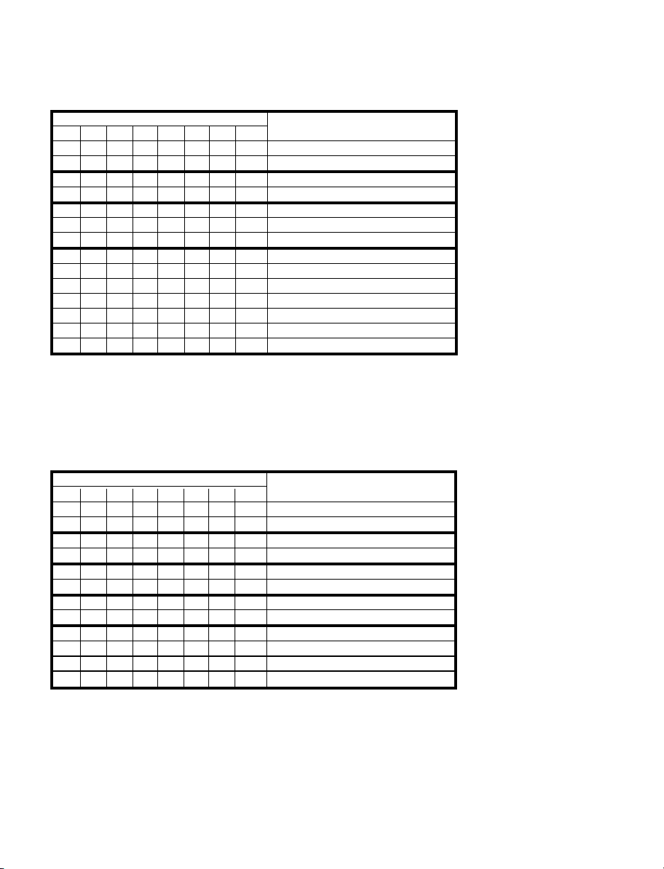
5.7.10 Communication Parameters (Command Index 10)
Description: COMM.PAR.76543210 means 8 bit positions of the Command Data.
BIT NUMBER FUNCTION
76543210
0 1 Stop Bit
1 2 Stop Bit
0 7 Bit
1 8 Bit
0 0 No Parity
0 1 Odd
1 0 Even
0 0 0 300 Baud
001 600
0 1 0 1200
0 1 1 2400
1 0 0 4800
1 0 1 9600
1 1 0 19200
Example: Set Baud Rate 9600, Odd Parity, 7 Bit, 1 Stop.
The command data is 00001101Bin = 0Dhex. Send: *W100D
5.7.11 Bus Format (Command Index 1F)
Description: BUSFORMAT.76543210 means 8 bit positions of the Command Data.
BIT NUMBER FUNCTION
76543210
0 Space
1 Carriage Return
0 Continuous
1 Command
0 RS-232
1 RS-485
0 N0 ECHO
1 ECHO
0 No Line Feed
1 Line Feed
0 No Modbus
1 Modbus
Example: Set Space, Continuous, RS-232, Echo, Line Feed, N/A
The command data is 00000110Bin = 06Hex. Send *W1F06
Page 33
29
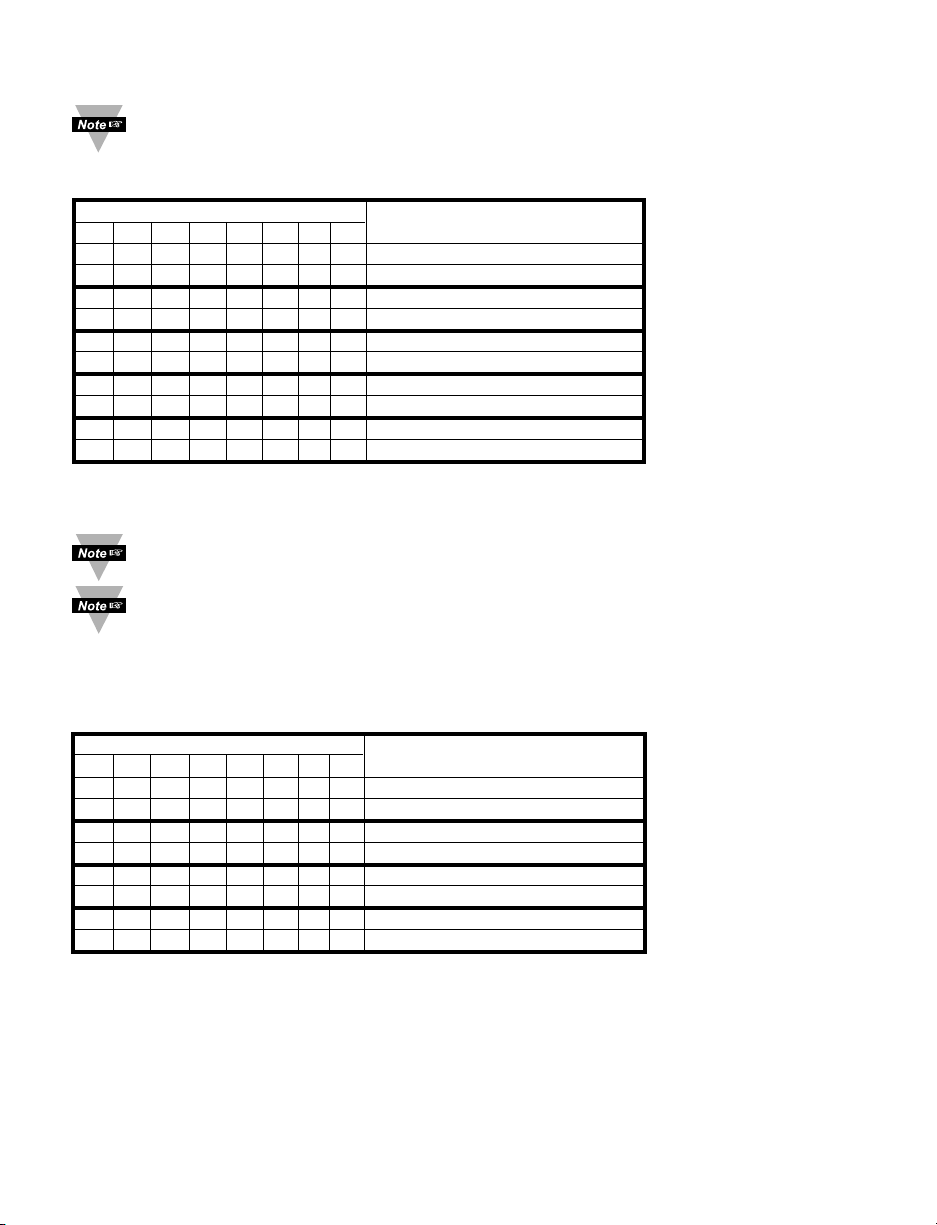
5.7.12 Data Format (Command Index 20)
DATAFORMAT is used for V01 command or continuous mode (RS-232)
Description: DATAFORMAT.76543210 means 8 bit positions of the Command Data.
BIT NUMBER FUNCTION
76543210
0 No Unit
1 Unit
0 No Valley or Gross
1 Valley or Gross
0 No Peak
1 Peak
0 No Reading
1 Reading
0 No Alarm Status
1 Alarm Status
Example: Set ID, Unit, No Valley, No Peak, Reading, No Status.
The command data is 11000010Bin = C2Hex. Send: *W20C2
ADDRESS is applicable for RS-485 standard only and can be 01 to 199
TRANSMIT TIME INTERVAL is applicable for RS-232 standard and Continuous Mode,
which specifies the time between transmission and the minimum time is 500 msec.
5.7.13 Miscellaneous (Command Index 24)
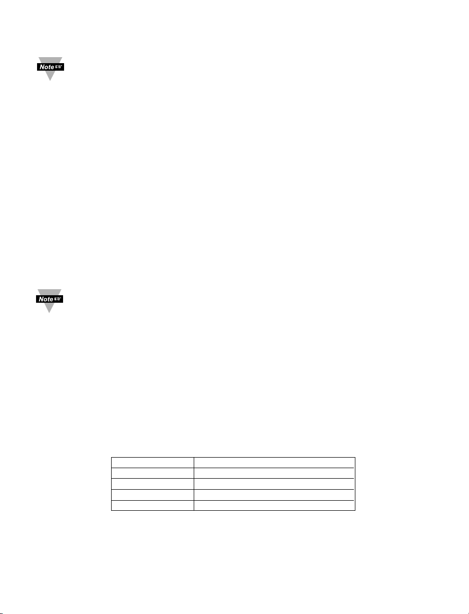
Description: MISCELLANEOUS.76543210 means 8 bit positions of the Command Data.
BIT NUMBER FUNCTION
76543210
0 SP Deviation Disable
1 SP Deviation Enable
0 Self Disable
1 Self Enable
0 Full ID Disable
1 Full ID Enable
0 Set Point ID Disable
1 Set Point ID Enable
Example: Set SP Enable, Self Disable, Full ID Enable, Set Point ID Disable.
The command data is 10001000Bin = 88Hex. Send: *W2088
Page 34
30
5.7.14 % Low and % Hi (Command Indexes 27 and 28)
Make sure the values of % Low and % Hi submenus are entered correctly
(% Hi can’t be more than 99% or % Hi should be always more than % Low). If
values entered incorrectly, instrument will reset these values to factory defaults
(% Low = 0, % Hi = 99 (63 Hex)
5.7.15 Reading Scale and Offset (Command Indexes 14 and 3A)
Description: RDGOFF.23~16, 15~8, 7~0 means 3 bytes x 8 bit positions of the
Reading Offset
RDGSC.23~16, 15~8, 7~0 means 3 bytes x 8 bit positions of the
Reading Scale
RDGOFF.23 = RDGOFF.22~20 = RDGOFF.19~0 =
0 positive offset DP+2 offset data
1 negative offset
RDGSC.23~20 = RDGSC.19 = RDGSC.18~0 =
DP+1 0 direct scale scale data
1 reverse scale
Example: To have an input of 4 to 20 mA displayed as 0 to 100
First make sure that the Decimal Point on your device is set to the proper position.
Then, disregard the decimal point position through Scale and Offset calculation.
For instance: to display 0 to 100 set decimal point into position 1 (FFFF);
to display 0 to 100.0 set decimal point into position 2 (FFF.F)
then, perform Scale and Offset calculation to display 0 to 1000.
The Low input value = min. input value * conversion number = 4(mA) x 500 = 2000
The High input value = max. input value * conversion number = 20(mA) x 500 = 10000 (9999)
where: conversion number is a coefficient of conversion between input values and real
display range.
The full range of the display = 10000, conversion number = 10000/20 = 500
See Table 5.9 below for proper conversion number
Table 5.9 Conversion Number
INPUT RANGE CONVERSION NUMBER
0 ~ 100 mV 10000 / (100 x 1) = 100 cts/mV
0 ~ 1 V 10000 / (1000 x 1) = 10 cts/mV
0 ~ 10 V 10000 / (1000 x 10) = 1 cts/mV
0 ~ 20 mA 10000 / (20 x 1) = 500 cts/mA
Page 35

31
Scaling:
To remap 4 – 20 mA to a displayed reading from 0 to 100 then use slope:
Rd2 – Rd1
Slope (Scale) = -------------------
In2 – In1I
where: Rd2 – Hi Display reading (100), Rd1 – Low Display reading (0)
In2 – Hi Input (20 x 500), In1 – Low Input (4 x 500)
1. Obtain a Scale Factor
Scale = (100-0) / (9999-2000) = 0.0125016
2. Rewrite the Scale Factor as an integer times an exponent
0.0125016 = 125016 E -7
3. Then Encode these values
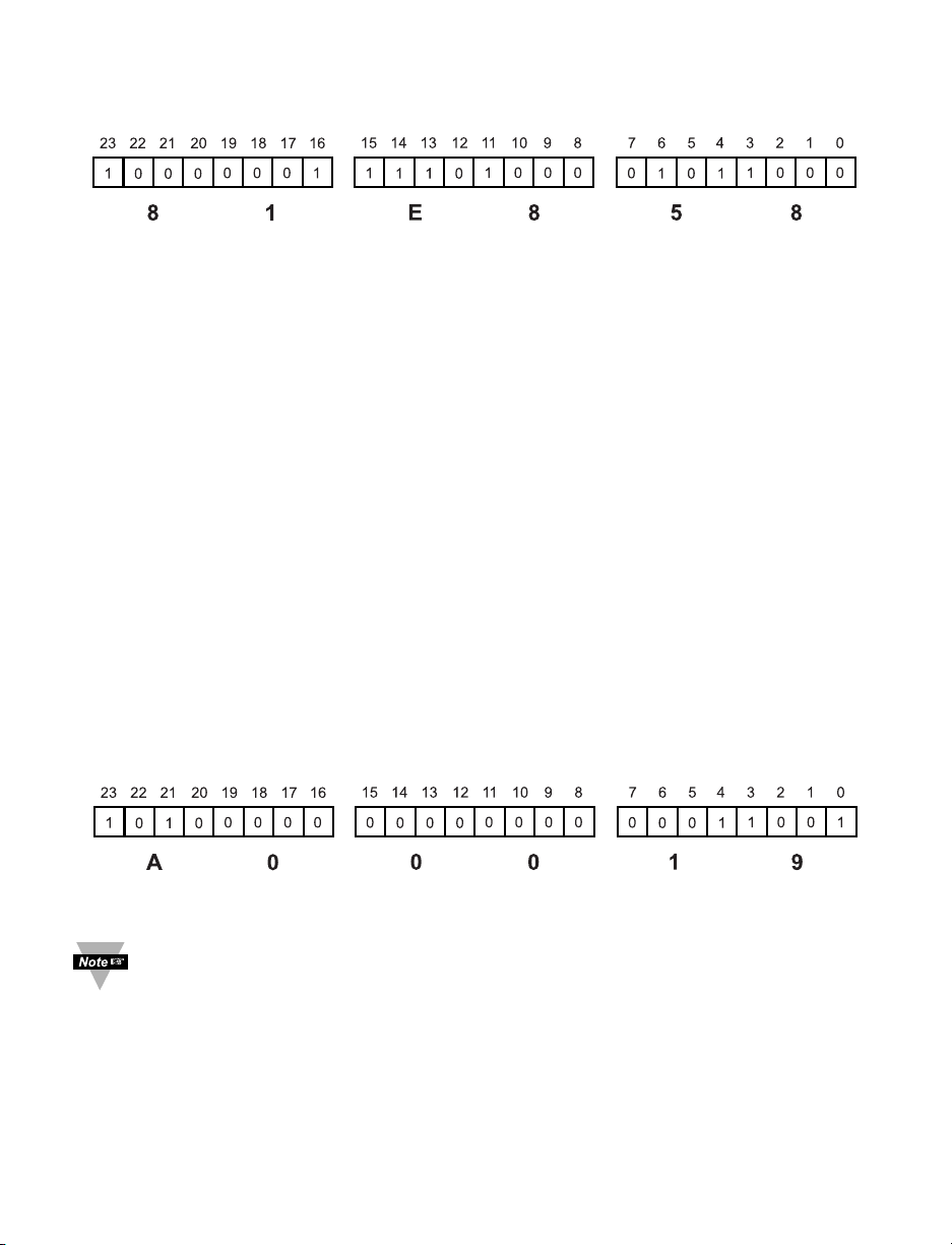
125016 Dec = 1E858 Hex - Reading Scale Data
(RDGSC.18 ~ 0 value stored into bits 0 - 18);
E –7 is represented as RDGSC.23 ~ 20 = 8 (DP = 7);
Direct Scale is represented as RDGSC.19 = 0 (direct scale);
Y2
Y1
Y = mX + b
WHERE: m - SLOPE (SCALE)
b - OFFSET
b
X1 X2
(Y2 - Y1)
m =
(X2 - X1)
Page 36
32
Binary Code:
Send command: *W1481E858 (scale = 81E858)
Offset:
Offset is found in the following equation: Reading = Scale x Input value + Offset (Y=mX+b)
or the equation can be rewritten as: Offset = Reading – Scale x Input Value (b=Y-mX)
1. Obtain the Offset Factor
Offset = 100 – (0.0125 x 10000) = (-25)
2. Rewrite the Offset Factor as an integer times an exponent
–25 x E0
3. Then encode these values
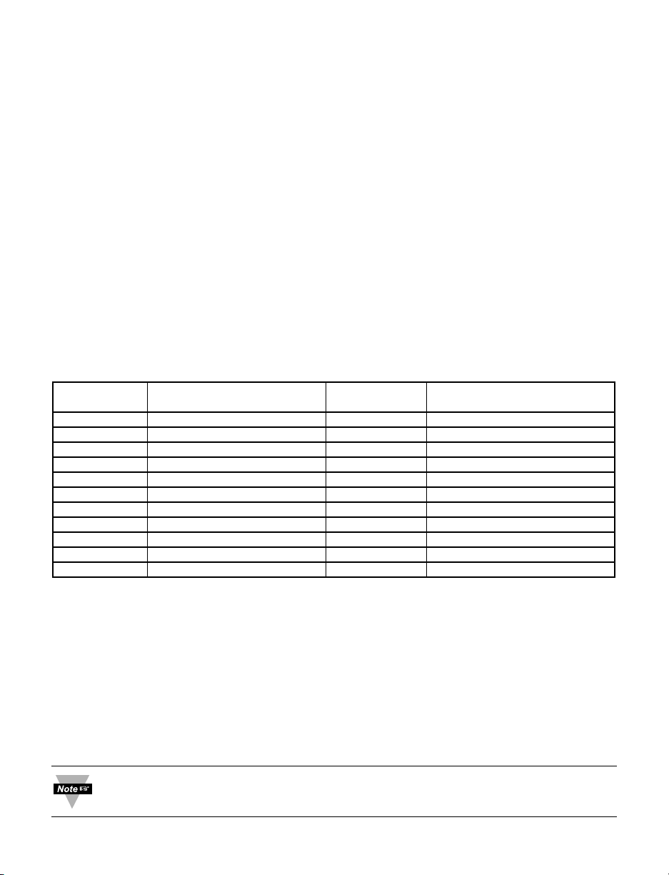
25 Dec = 00019 Hex Offset Data (RDGOFF.19 ~ 0 value stored into bits 0 – 19)
E0 is represented as RGDOFF.22 ~ 20 = 2 (DP+2=0+2)
Offset is negative represented RDGOFF.23 = 1
Binary Code:
Send command: *W03A00019 (offset=A00019)
See Appendix A for Reading Scale and Offset of Process/Strain Gage Instrument
with 10 Linearization Points
Page 37
33
5.7.16 Grouping Commands with the Same Formats
1. The following are of the same format as the Alarm 1 Low data format:
Set Point 1 (command index 01), Set Point 2 (command index 02)
Alarm 1 High (command index 13), Alarm 2 Low (command index 15),
Alarm 2 High (command index 16), C.J. Offest Adjustment
(command index 25).
2. There are two commands using the same Scale-Type format:
Reading Scale (command index 14) and Analog Output Scale
(command index 0F)
3. There are two commands using the same Offset-Type format:
Reading Offset (command index 03) and Analog Output Offset
(command index 04)
4. Table 5.10 below shows the simple natural numbers, which have a simple
data format.
Table 5.10 Commands with Numeric Data Format
Command Function # of Range
index characters
05 ID Code 2 0 ~ 9999
22 Transmit Time Interval 4 0 ~ 1999 (0 = 500 ms)
1A Cycle 1 2 1 ~ 199 Sec
1D Cycle 2 2 1 ~ 199 Sec
21 Address 2 1 ~ 199
17 PB1/Dead Band 1 4 0 ~ 9999 Counts
1C PB1/Dead Band 2 4 0 ~ 9999 Counts
18 Reset 1 4 0 ~ 3999 Sec
19 Rate 1 4 0 ~ 3999 Sec
27 %Low 2 0 ~ 98%
28 %High 2 0 ~ 99%
Example: Set Proportional Band 1 (PB 1) to 150
The command data = 0096Hex. Send: *W170096
5. Time Formats:
Loop Break Time Value MM * 100 + SS (encoded as a 4 digit hex number)
Ramp Time HH * 100 + MM (encoded as a 4 digit hex number)
Soak Time HH * 100 + MM (encoded as a 4 digit hex number)
Example: Set Loop Break Time to 10 minutes 25 seconds (10:25)
The command data = 0401Hex. Send: *W0B0401
To communicate when the Continuous Mode is enabled, the Continuous Mode
must be stopped by sending Crtl S (Xoff) and then send ^AE
Page 38

34
PART 6
MODBUS PROTOCOL
To Enable the Modbus Protocol, set Modbus menu item to “Yes” in the Bus
Format Submenu of the Communication Menu.
6.1 Introduction
Modbus Protocol defines a message structure that iLD Big Display devices will recognize
and use, regardless of the type of networks over which they communicate. It describes
the process a device uses to request access to another device, how it will respond to
requests from the other devices, and how errors will be detected and reported. It
establishes a common format for the layout and contents of message fields.
The Modbus Protocol provides the internal standard that the iLD Big Display devices use
for parsing messages. During communications on a Modbus network, the protocol
determines how each instrument will know its device address, recognize a message
addressed to it, determine the kind of action to be taken, and extract any data or other
information contained in the message. If a reply is required, the iLD Big Display will
construct the reply message and send it using Modbus protocol.
Modbus defines a digital communication network to have only one MASTER and one or
more SLAVE devices. Either a single (point-to-point) or multi-drop network (multipoint) is
possible.
iLD Big Display devices communicate on standard Modbus networks using RTU
(Remote Terminal Unit) transmission mode.
6.2 RTU Mode
In RTU Mode, each eight-bit byte in a message contains two four-bit hexadecimal
characters. The main advantage of this mode is that its greater character density allows
better data throughput than ASCII for the same baud rate. Each message must be
transmitted in a continuous stream.
The following format used for each byte sent and received by i-Series instrument
in RTU Mode:
1. Eight-bit binary, Hexadecimal (0 ... 9, A ... F)
2. Two hexadecimal characters contained in each eight-bit field of the message
3. 1 start bit, 8 data bits, 1 Stop Bit (No Parity Bit)
The figure below shows the bit sequences when byte transmitted in RTU Mode.
LSB – Least Significant bit sent first
Page 39

35
The Modbus Message frame is shown below
DEVICE FUNCTION DATA CRC
ADDRESS CODE CHECK
8 BITS 8 BITS k x 8 BITS 16 BITS
nn nn nnn... nnnn
where: n – character, k – integers depend on the contents of the data format.
6.3 Device Address
The address message frame contains eight bits. The slave device addresses are in the
range of 1 ... 199 decimal. A master addresses a slave by placing the slave address in
the address field of the message. When the slave sends its response, it places its own
address in this address field of the response to let the master know which slave is
responding. Address 0 is used for the write command broadcast that commands all
devices on network, which all slave devices recognize.
6.4 Function Code
The function code field of a message frame contains eight bits (RTU). Valid codes are in
the range of 1 ... 255 decimal. Of these, some codes are applicable for i-Series
controllers. When a message is sent from a master to a slave device the function code
field tells the slave what kind of action to perform.
The following functions are supported by iLD Big Display devices:
Table 6.1 Function Code
Function Code Function Description
03 Read holding register Reads the binary contents of holding
registers in the slave
04 Read input register Reads the binary contents of input register
in the slave.
06 Preset (Write to) Preset (Write) a value into single holding
single register register
08 Diagnostic Series of tests for checking communication
between master and slave
When the slave responds to the master, it uses the function code field to indicate either a
normal (error-free) response or that some kind of error occurred (called an exception
response). For a normal response, the slave simply echoes the original function code.
For an exception response, the slave returns a code that is equivalent to the original
function code with its most significant bit set to a logic 1.
6.5 Data Field
The data field is constructed using sets of two hexadecimal digits, in the range of 00 to
FF hexadecimal. The data field of messages sent from a master to slave devices
contains additional information, which the slave must use to take the action defined by
the function code. This can include items like discrete and register addresses, the
quantity of items to be handled, and the count of actual data bytes in the field.
Page 40

6.6 CRC Checking
With RTU Mode the error checking field contains a 16-bit value implemented as two
eight-bit bytes (High order byte and Low order byte). The error check value is the result
of a Cyclical Redundancy Check (CRC) Calculation performed on the message contents.
After building a message (address, function code, data) the transmitting device
calculates a CRC Code and puts it to the end of the message. A receiving device will
calculate a CRC Code from the message it has received and compare against
transmitted CRC Code. If these CRC Codes are different, there has been a
communication error. iLD Big Display devices will not reply if they detect a CRC Error.
Sequences of CRC calculation:
1. Load a 16 bit CRC register with all 1’s.
2. Apply first 8 bit byte of the message to the low order byte (LB) of the contents of the
register.
3. Exclusive OR these 8 bit with the register contents.
4. Shift the result one bit to the right with zero entering into the high order byte (HB)
position and evaluate the LB.
5. If over flow bit in LB is 1, exclusive OR the latest register contents with A001 Hex
value.
6. If over flow bit in LB is 0, no exclusive OR occurs (repeat step 4).
7. Repeat steps 4, 5 and 6 until 8 shifts have been performed.
8. Apply next 8 bit byte of the message to the LB contents of the register.
9. Exclusive OR these 8 bit with the register contents.
10. Repeat steps 4 to 9 until all bytes of the message have been processed.
11. The final content of the register is the CRC value.
Examples of CRC calculation sees in Appendix B
When CRC is placed into the end of the message, the low order byte of the CRC
will be transmitted first, followed by the High order byte.
36
Page 41

6.7 Modbus RTU Registers
The table below shows the Modbus registers supported by iLD Big Display devices.
Table 6.2 Modbus Registers
FUNCTION REGISTER FUNCTION VALUE, RANGE
CODE (Decimal)
NO 0 N/A
03/04, 06 1 SETPOINT 1 -1999 to 1999
03/04, 06 2 SETPOINT 2 -1999 to 1999
NO 3 N/A
NO 4 N/A
03/04, 06 5 ID 0 to 9999
NO 6 N/A
03/04, 06 7 INPUT 0 to 255
03/04, 06 8 RDGCNF 0 to 255
03/04, 06 9 ALR1CNF 0 to 255
03/04, 06 10 ALR2CNF 0 to 255
03/04, 06 11 LOOP BREAK TIME 00:00 to 99:59
03/04, 06 12 OUT1CNF 0 to 255
03/04, 06 13 OUT2CNF 0 to 255
03/04, 06 14 RAMP TIME 00:00 to 99:59
NO 15 N/A
03/04, 06 16 COMM. PARAMETERS 0 to 255
NO 17 N/A
03/04, 06 18 ALR1 LOW -1999 to 9999
03/04, 06 19 ALR1 HI -1999 to 9999
NO 20 N/A
03/04, 06 21 ALR2 LOW -1999 to 9999
03/04, 06 22 ALR2 HI -1999 to 9999
03/04, 06 23 PB1/DEAD BAND 1 0 to 9999
03/04, 06 24 RESET 1 0 to 3999
03/04, 06 25 RATE 1 0 to 399.9
03/04, 06 26 CYCLE 1 1 to 199
NO 27 N/A
03/04, 06 28 PB2/DEAD BAND 2 0 to 9999
03/04, 06 29 CYCLE 2 1 to 199
03/04, 06 30 SOAK TIME 00:00 to 99:59
03/04, 06 31 BUS FORMAT 0 to 255
03/04, 06 32 DATA FORMAT 0 to 255
03/04, 06 33 ADDRESS 0 to 199
03/04, 06 34 TRANSIT TIME 0 to 9999
NO 35 N/A
NO 36 N/A
NO 37 N/A
03/04, 06 38 RECOGNITION CHAR. 32 to 126
03/04 39 PROCESS VALUE
03/04 40 PEAK VALUE
03/04 41 VALLEY VALUE
03/04 42 SOFTWARE VERSION
06 43 RESET
37
Page 42
38
6.8 Command Format
The following formats are used to SEND commands by computer and RETURNED by
the device.
6.8.1 Read Multiple Register (03 or 04)
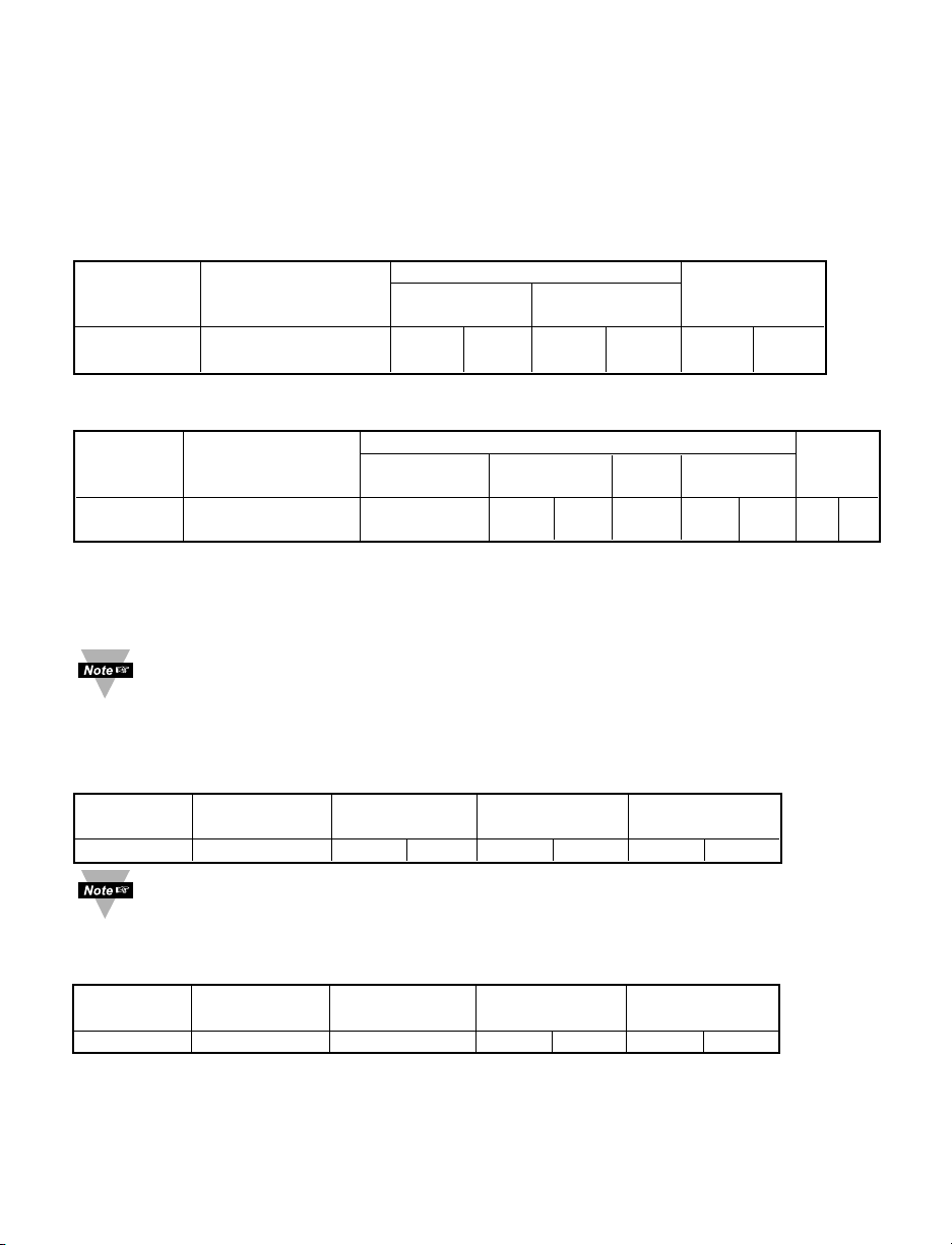
SENT TO DEVICE:
DEVICE FUNCTION CODE DATA
ADDRESS 03 or 04 STARTING NUMBER OF CRC
REGISTERS REGISTERS
1 BYTE 1 BYTE HB LB HB LB LB HB
nn 03 00 nn 00 nn nn nn
RETURNED FROM DEVICE:
DEVICE FUNCTION CODE DATA
ADDRESS 03 or 04 NUMBER OF FIRST .... n CRC
BYTES REGISTER REGISTER
1 BYTE 1 BYTE 1 BYTE HB LB .... HB LB LB HB
nn 03 nn nn nn nn nn nn nn
Where: HB – High Order Byte
LB – Lower Order Byte
Unused bits are set to zero
iLD Big Display devices support only Read Single Register, so the number of
registers should always set to 1.
Example:
SENT TO DEVICE: Address 1, Read (03) register 1 (Setpoint 1)
DEVICE FUNCTION STARTING NUMBER OF CRC
ADDRESS CODE REGISTER REGISTERS
01 03 00 01 00 01 D5 CA
To determine the appropriate registers see Table 6.2
RETURNED FROM DEVICE: Setpoint 1 set to 100.0
DEVICE FUNCTION NUMBER OF VALUE OF CRC
ADDRESS CODE BYTES REGISTERS
01 03 02 03 E8 B8 FA
03E8 Hex = 1000 Dec
These returned data do not specify the Decimal Point position. The following command
will determine the Decimal Point position.
Page 43
Example:
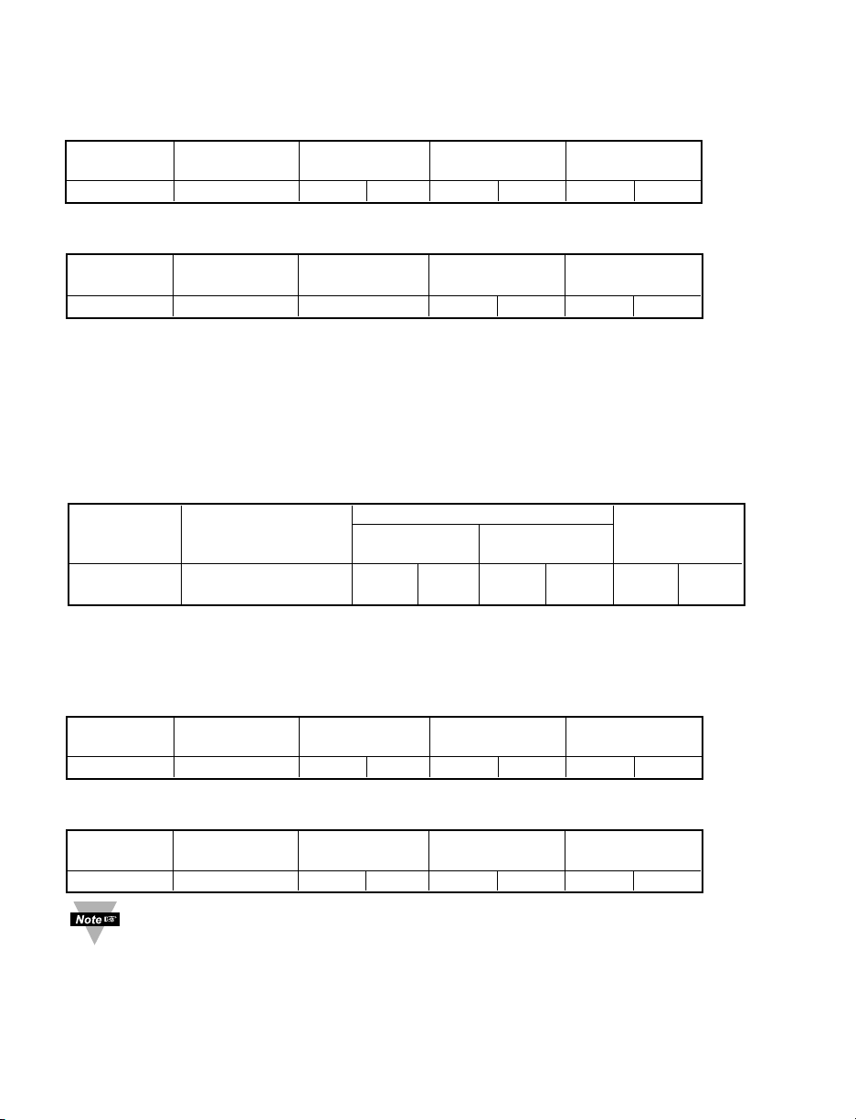
SENT TO DEVICE: Address 09, Read (03) register 08 (Reading Configuration)
DEVICE FUNCTION STARTING NUMBER OF CRC
ADDRESS CODE REGISTER REGISTERS
09 03 00 08 00 01 04 80
RETURNED FROM DEVICE:
DEVICE FUNCTION NUMBER OF VALUE OF CRC
ADDRESS CODE BYTES REGISTERS
09 03 02 00 4A D8 72
004A Hex = 01001010 Bin. This value calls for Decimal Point position number 2 (FFF.F)
– see example in 5.7.2 for Reading Configuration.
6.8.2 Write to Single Register (06)
The following command will write a parameter to the single register.
Sent to/Return from device :
DEVICE FUNCTION CODE DATA
ADDRESS 06 REGISTER DATA/ CRC
VALUE
1 BYTE 1 BYTE HB LB HB LB LB HB
nn 06 00 nn 00 nn nn nn
Example: Set Alarm1 Low (register 18) to 300 Dec (12C Hex)
SEND TO DEVICE: Address 20 (14 Hex), write (06) to register 18 (12 Hex) value 300
(12C Hex)
DEVICE FUNCTION REGISTER DATA/ CRC
ADDRESS CODE VALUE
14 06 00 12 01 2C 2B 47
RETURNED FROM DEVICE:
DEVICE FUNCTION REGISTER DATA/ CRC
ADDRESS CODE VALUE
14 06 00 12 01 2C 2B 47
iLD Big Display devices support only Write to Single Register command
39
Page 44
40
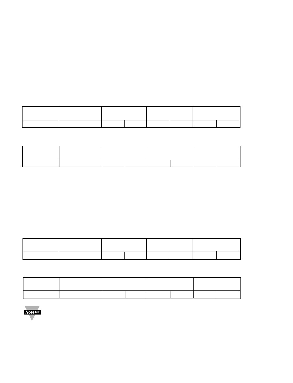
Example: Set Alarm2 Low to –100.0 on Device address 20
We have to send two commands to accomplish this task.
First, we have to set decimal point into the position 2 (FFF.F) and then, set value of
Alarm 2 Low to –1000 counts (disregard decimal point).
1. Set Decimal Point
Set the Decimal point to the position 2 (FFF.F), Temperature unit ºF, Filter constant 4
- see example in 5.7.2
SEND TO DEVICE: Address 20 (Hex 14), write (06) to register 8, data 4A
DEVICE FUNCTION REGISTER DATA/ CRC
ADDRESS CODE VALUE
14 06 00 08 00 4A 8B 3A
RETURNED FROM DEVICE:
DEVICE FUNCTION REGISTER DATA/ CRC
ADDRESS CODE VALUE
14 06 00 08 00 4A 8B 3A
2. Conversion the Decimal value of (–1000) to Hexadecimal Value:
N = +1000 Dec = 0000 0011 1110 1000 Bin = 2 bytes or 16 bits
1’s complement of N = 1111 1100 0001 0111 Bin = Not N
2’s complement of N = 1111 1100 0001 1000 Bin = 1’s complement of N + 1LSB
F C 1 8 Hex
SEND TO DEVICE: Address 20 (14 Hex), write (06) to register 21 (15 Hex) value
(–1000) (FC18 Hex)
DEVICE FUNCTION REGISTER DATA/ CRC
ADDRESS CODE VALUE
14 06 00 15 FC 18 DB C1
RETURNED FROM DEVICE:
DEVICE FUNCTION REGISTER DATA/ CRC
ADDRESS CODE VALUE
14 06 00 15 FC 18 DB C1
For examples of how to Read/Write data code for INPUT, RDGCNF, ALR1CNF,
ALR2CNFG, OUT1CNF, OUT2CNF, COLOR, COMM.PARAMETERS,
BUSFORMAT, DATAFORMAT see section 5.7 of this manual.
Page 45
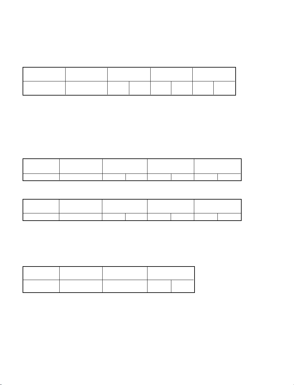
6.8.3 Diagnostic Command
This command echoes the sent message to indicate that the communication link is
established correctly.
SEND TO/RETURN FROM DEVICE:
DEVICE FUNCTION DIAGNOSTIC LOOPBACK CRC
ADDRESS CODE CODE DATA
1 BYTE 1 BYTE HB LB HB LB LB HB
nn 08 00 00 nn nn nn nn
Where: Diagnostic Code is two byte code to determine the type of test to be performed.
iLD Big Display devices supported only “00” code which requested slave to echo sent
command back to the master.
Example:
SEND TO DEVICE: Address 01, Diagnostic command (08), data value 8755 Dec
(2233 Hex)
DEVICE FUNCTION DIAGNOSTIC LOOPBACK CRC
ADDRESS CODE CODE DATA
01 08 22 33 00 00 BE B8
RETURNED FROM DEVICE:
DEVICE FUNCTION DIAGNOSTIC LOOPBACK/ CRC
ADDRESS CODE CODE DATA
01 08 22 33 00 00 BE B8
6.8.4 Error Response
When a device can not properly respond to the command due to incorrect or corrupted
command, it will respond with an error message. The error massage has the following
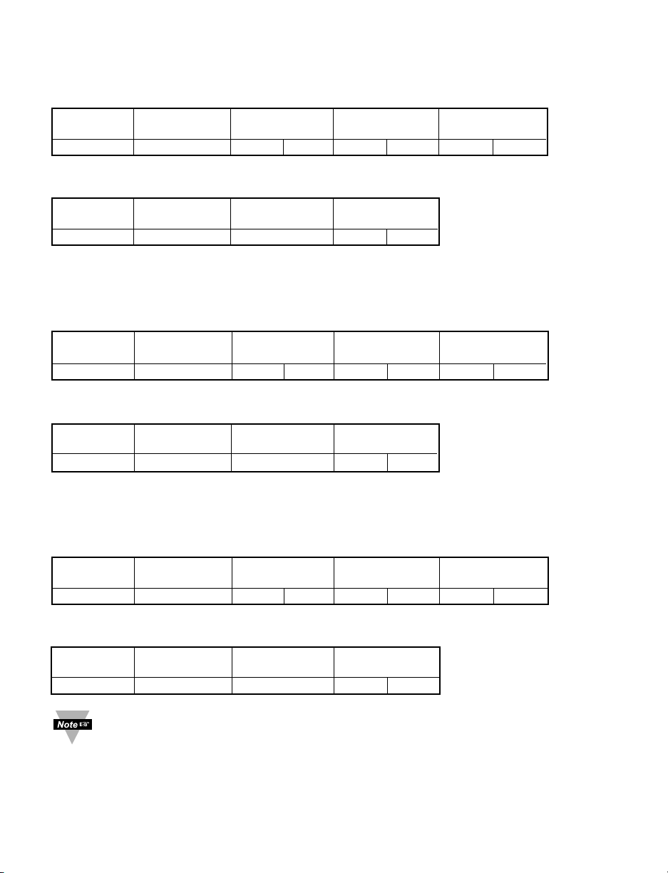
format:
DEVICE FUNCTION ERROR CRC
ADDRESS CODE RESPONSE
1 BYTE 1 BYTE 1 BYTE LB HB
nn nn nn nn nn
iLD Big Display devices support the following error code messages:
02 – read from/write to the illegal register – read from/write to the register, which is
inactive, or not supported by iLD Big Display devices
03 – write an illegal value – write out of range value
4141
Page 46
4242
Example:
SEND TO DEVICE: Address 05, read (03) register 04 - inactive (see Table 6.2)
DEVICE FUNCTION STARTING NUMBER OF CRC
ADDRESS CODE REGISTER REGISTERS
05 03 00 04 00 01 C4 4F
RETURNED FROM DEVICE:
DEVICE FUNCTION ERROR CRC
ADDRESS CODE RESPONSE
05 83 02 81 30
Example:
SEND TO DEVICE: Address 120 (Hex 78), write (06) to register 35 (Hex 23) - inactive
(see Table 6.2)
DEVICE FUNCTION REGISTER DATA/ CRC
ADDRESS CODE VALUE
78 06 00 23 00 00 73 A9
RETURNED FROM DEVICE:
DEVICE FUNCTION ERROR CRC
ADDRESS CODE RESPONSE
78 86 02 12 78
Example:
SEND TO DEVICE: Address 01, write (06) to register 12 (Hex C) value 300 (Hex 12C)
–out of range (see Table 6.2)
DEVICE FUNCTION REGISTER DATA/ CRC
ADDRESS CODE VALUE
01 06 00 0C 01 2C 49 84
RETURNED FROM DEVICE:
DEVICE FUNCTION ERROR CRC
ADDRESS CODE RESPONSE
01 86 03 02 61
When a device returns an error message, it adds 80 Hex to the Function Code
(03 + 80 = 83 or 06 + 80 = 86)
Page 47
APPENDIX A
Reading Scale and Offset for Process/Strain Gage Instrument with 10 Linearization
Points (Command Indexes 2B to 33, 34 to 3C, 3D to 45)
Description: RDGOFF.23~16, 15~8, 7~0 means 3 bytes x 8 bit positions of the
Reading Offset
RDGSC.23~16, 15~8, 7~0 means 3 bytes x 8 bit positions of the
Reading Scale
RDGOFF.23 = RDGOFF.22~20 = RDGOFF.19~0 =
0 positive offset DP+2 offset data
1 negative offset
RDGSC.23~20 = RDGSC.19 = RDGSC.18~0 =
DP+1 0 direct scale scale data
1 reverse scale
Example:
The following example assumes load cells with this specification:
Maximum Load: 100 lbs
Output: 3.0 mV/V
Sensor Excitation: 10 Vdc
Maximum Sensor Output = (Output) x (Sensor Excitation) = 3.0 (mV/V) x 10 (V) = 30 mV
Input Value (In) = (Sensor Output) x (Conversion Number) x (Multiplier)
See Tables A.1 and A.2 below for proper Conversion and Multiplier Numbers.
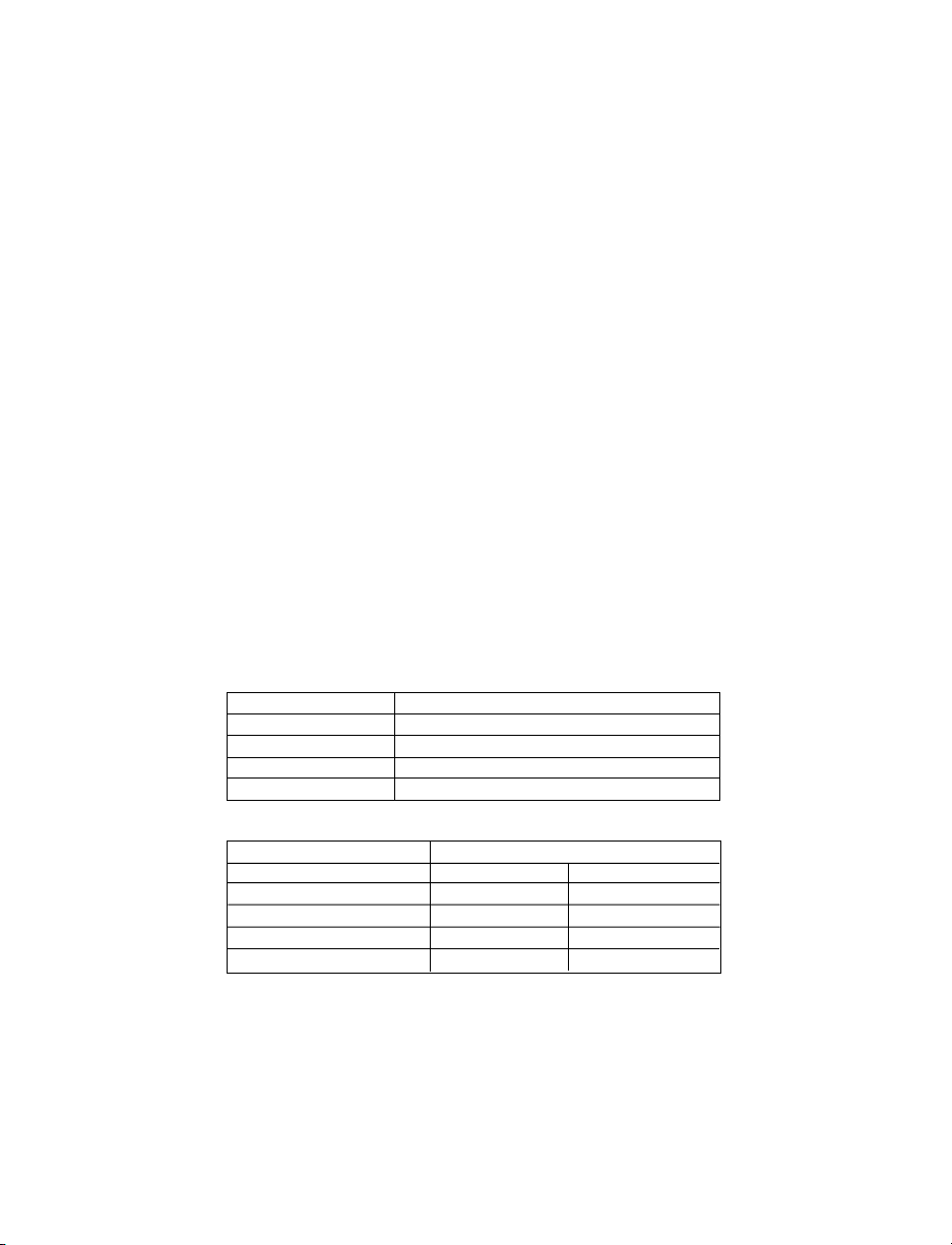
Table A.1 Conversion Number
INPUT RANGE CONVERSION NUMBER
0 ~ 100 mV 10000 / (100 x 1) = 100 cts/mV
0 ~ 1 V 10000 / (1000 x 1) = 10 cts/mV
0 ~ 10 V 10000 / (1000 x 10) = 1 cts/mV
0 ~ 20 mA 10000 / (20 x 1) = 500 cts/mA
Table A.2 Input Resolution Multiplier
INPUT RANGE RESOLUTION
LOW HIGH
0 ~ 100 mV 1.0 10.0
0 ~ 1 V 1.0 10.0
0 ~ 10 V 1.0 10.0
0 ~ 20 mA 1.0 10.0
Determine IN min and IN max Input Range and Resolution. For our transducer select
0 - 100 mV range and Low resolution.
IN min = 0 (mV) x 100 (cts/mV) x 1.0 = 0
IN max = 30 (mV) x 100 (cts/mV) x 1.0 = 3000
43
Page 48
Determine correct values for Display reading (Rd min and Rd max). In most cases, Rd min
and Rd max are equal to the minimum and maximum of the transducer output range.
Rd min = 0
Rd max = 100.0
We have to scale our meter to have an input 0 to 3000 (30 mV) displayed as 0 to 100.0 (lbs)
Assume that the shape of the transducer response characteristic is equal to the shape of the
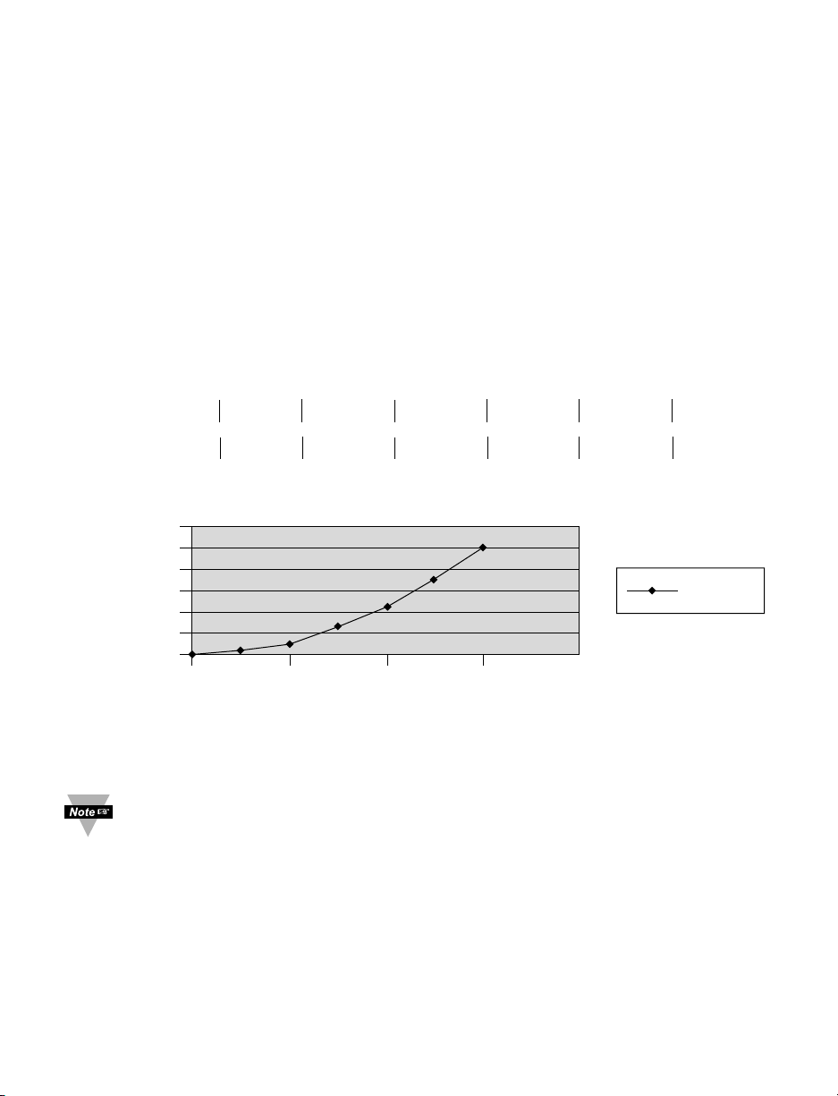
parabola (Y=KX^2)
Output = K x Input^2, there K = Output / Input^2 = 100.0 / (3000^2) = 1 / (9 x 10^4)
Output = Input^2/(9 x 10^4)
Let’s build the response characteristic of our transducer based on the seven inputs within the
range of the transducer (7 linearization points)
Input (X): In 1=0 In 2=500 In 3=1000 In 4=1500 In 5=2000 In 6=2500 In 7=3000
-------------------------------------------------------------------------------------------------------------------------Output (Y): Rd 1=0 Rd 2=2.8 Rd 3=11.0 Rd 4=25.0 Rd 5=44.4 Rd 6=69.4 Rd 7=100.0
120
100
80
60
40
20
0
0 1000 2000 3000 4000
The following commands need to be sent to the meter to create this response characteristic.
First make sure that the Decimal Point on your device is set to the proper position.
Then, disregard the decimal point position through Scale and Offset calculation.
For instance: to display 0 to 100 set decimal point into position 1 (FFFF);
to display 0 to 100.0 set decimal point into position 2 (FFF.F)
then, perform Scale and Offset calculation to display 0 to 1000.
44
Reading
Output
Input
Output
Page 49

1. The command for the number of linearization points is 29 (Table 5.4) and the data has
an offset of -2. Send command: *W2905 means 7 points of linearization are active.
2. Out of ten points the very first one is not available through the communication
commands. The nine points from 1st to 9th must represent min and max of each interval
respectively, and the points in between them must be progressively incrementing. The
commands for these points are 2B to 33 (Table 5.4)
2.1 Send command: *W2B2001F4 means 5 mV input for Scale 1/Offset 1 is active, DP=2
2.2 Send command: *W2C2003E8 means 10 mV input for Scale 2/Offset 2 is active, DP=2
2.3 Send command: *W2D2005DC means 15 mV input for Scale 3/Offset 3 is active, DP=2
2.4 Send command: *W2E2007D0 means 20 mV input for Scale 4/Offset 4 is active, DP=2
2.5 Send command: *W2F2009C4 means 25 mV input for Scale 5/Offset 5 is active, DP=2
2.6 Send command: *W30200BB8 means 30 mV input for Scale 6/Offset 6 is active, DP=2
3. Calculate Scale.
Rd(n) - Rd(n-1)
Scale = -------------------- , where n is an interger
IN(n) - IN(n-1)
The commands for these points are 34 to 3C (Table 5.4)
3.1 Scale 1 = (28 - 0) / (500 - 0) = 56000 x E-6
56000 Dec = DAC0 Hex is a Reading Scale Data (RDGSC1.18~0 = DAC0)
E-6 represented as RDGSC1.23~20 = 7 (DP+1=7)
RDGSC1.19 = 0 (direct scale)
Send command: *W3470DAC0
3.2 Scale 2 = (110 - 28) / (1000 - 500) = 164000 x E-6
RDGSC2.18~0 = 164000 Dec = 280A0 Hex
RDGSC2.23~20 = 7
RDGSC2.19~0 = 0
Send command: *W357280A0
3.3 Scale 3 = (250 - 110) / (1500 - 1000) = 280000 x E-6
RDGSC3.18~0 = 280000 Dec = 445C0 Hex
RDGSC3.23~20 = 7
RDGSC3.19~0 = 0
Send command: *W367445C0
45
Page 50

3.4 Scale 4 = (444 - 250) / (2000 - 1500) = 388000 x E-6
RDGSC4.18~0 = 388000 Dec = 5EBA0 Hex
RDGSC4.23~20 = 7
RDGSC4.19~0 = 0
Send command: *W3775EBA0
3.5 Scale 5 = (694 - 444) / (2500 - 2000) = 500000 x E-6
RDGSC5.18~0 = 500000 Dec = 7A120 Hex
RDGSC5.23~20 = 7
RDGSC5.19~0 = 0
Send command: *W3877A120
3.6 Scale 6 = (1000 - 694) / (3000 - 2500) = 612000 x E-6
RDGSC6.18~0 = 612000 Dec = 956A0 Hex
RDGSC6.23~20 = 7
RDGSC6.19~0 = 0
Send command: *W397956A0
4. Calculate Offset.
Reading = Scale x Input + Offset
Offset (n) = Reading (n) - Scale (n) x Input (n), where n is an integer
The commands for these points are 3D to 45 (Table 5.4)
4.1 Offset 1 = 28 - (28 - 0) / (500 - 0) x 500 = 0
RDGOFF1.19~0 = 0 Dec = 0 Hex
RDGOFF1.22~20 = 2 (DP+2)
RDGOFF1.23 = 1 (Offset is negative)
Send command: *W3DA00000
4.2 Offset 2 = 110 - (110 - 28) / (1000 - 500) x 1000 = -54 x E0
RDGOFF2.19~0 = 54 Dec = 36 Hex
RDGOFF2.22~20 = 2 (DP+2)
RDGOFF2.23 = 1 (Offset is negative)
Send command: *W3EA00036
4.3 Offset 3 = 250 - (250 - 110) / (1500 - 1000) x 1500 = -170 x E0
RDGOFF3.19~0 = 170 Dec = AA Hex
RDGOFF3.22~20 = 2 (DP+2)
RDGOFF3.23 = 1 (Offset is negative)
Send command: *W3FA000AA
4.4 Offset 4 = 444 - (444 - 250) / (2000 - 1500) x 2000 = -332
RDGOFF4.19~0 = 332 Dec = 14C Hex
RDGOFF4.22~20 = 2 (DP+2)
RDGOFF4.23 = 1 (Offset is negative)
Send command: *W40A0014C
46
Page 51

4.5 Offset 5 = 694 - (694 - 444) / (2500 - 2000) x 2500 = -556
RDGOFF5.19~0 = 556 Dec = 22C Hex
RDGOFF5.22~20 = 2 (DP+2)
RDGOFF5.23 = 1 (Offset is negative)
Send command: *W41A0022C
4.6 Offset 6 = 1000 - (1000 - 694) / (3000 - 2500) x 3000 = -836
RDGOFF6.19~0 = 836 Dec = 344 Hex
RDGOFF6.22~20 = 2 (DP+2)
RDGOFF6.23 = 1 (Offset is negative)
Send command: *W42A00344
A Hard reset command (*Z02) should be sent at the end in order to load the
changes into Volatile memory.
47
Page 52

48
APPENDIX B ASCII Chart
ASCII Dec Hex Binary ASCII Dec Hex Binary
Char No parity Char No Parity
NUL 00 00 00000000 @ 64 40 01000000
SOH 01 01 00000001 A 65 41 01000000
STX 02 02 00000010 B 66 42 01000010
ETX 03 03 00000011 C 67 43 01000011
EOT 04 04 00000100 D 68 44 01000100
ENQ 05 05 00000101 E 69 45 01000101
ACK 06 06 00000110 F 70 46 01000110
BEL 07 07 00000111 G 71 47 01000111
BS 08 08 00001000 H 72 48 01001000
HT 09 09 00001001 I 73 49 01001001
LF 10 0A 00001010 J 74 4A 01001010
VT 11 0B 00001011 K 75 4B 01001011
FF 12 0C 00001100 L 76 4C 01001100
CR 13 0D 00001101 M 77 4D 01001101
SO 14 0E 00001110 N 78 4E 01001110
SI 15 0F 00001111 O 79 4F 01001111
DLE 16 10 00010000 P 80 50 01010000
DC1 17 11 00010001 Q 81 51 01010001
DC2 18 12 00010010 R 82 52 01010010
DC3 19 13 00010011 S 83 53 01010011
DC4 20 14 00010100 T 84 54 01010100
NAK 21 15 00010101 U 85 55 01010101
SYN 22 16 00010110 V 86 56 01010110
ETB 23 17 00010111 W 87 57 01010111
CAN 24 18 00011000 X 88 58 01011000
EM 25 19 00011001 Y 89 59 01011001
SUB 26 1A 00011010 Z 90 5A 01011010
ESC 27 1B 00011011 [ 91 5B 01011011
FS 28 1C 00011100 \ 92 5C 01011100
GS 29 1D 00011101 ] 93 5D 01011101
RS 30 1E 00011110 ^ 94 5E 0101111 0
US 31 1F 000 11111
_
95 5F 01 011111
SP 32 20 00100000
`
96 60 01100000
! 33 21 00100001 a 97 61 01100001
" 34 22 00100010 b 98 62 01100010
# 35 23 00100011 c 99 63 01100011
$ 36 24 00100100 d 100 64 01100100
% 37 25 00100101 e 101 65 01100101
& 38 26 00100110 f 102 66 01100110
39 27 00100111 g 103 67 01100111
( 40 28 00101000 h 104 68 01101000
) 41 29 00101001 I 105 69 01101001
* 42 2A 00101010 j 106 6A 01101010
+ 43 2B 00101011 k 107 6B 01101011
44 2C 00101100 l 108 6C 01101100
- 45 2D 00101101 m 109 6D 01101101
46 2E 00101110 n 110 6E 01101110
Page 53
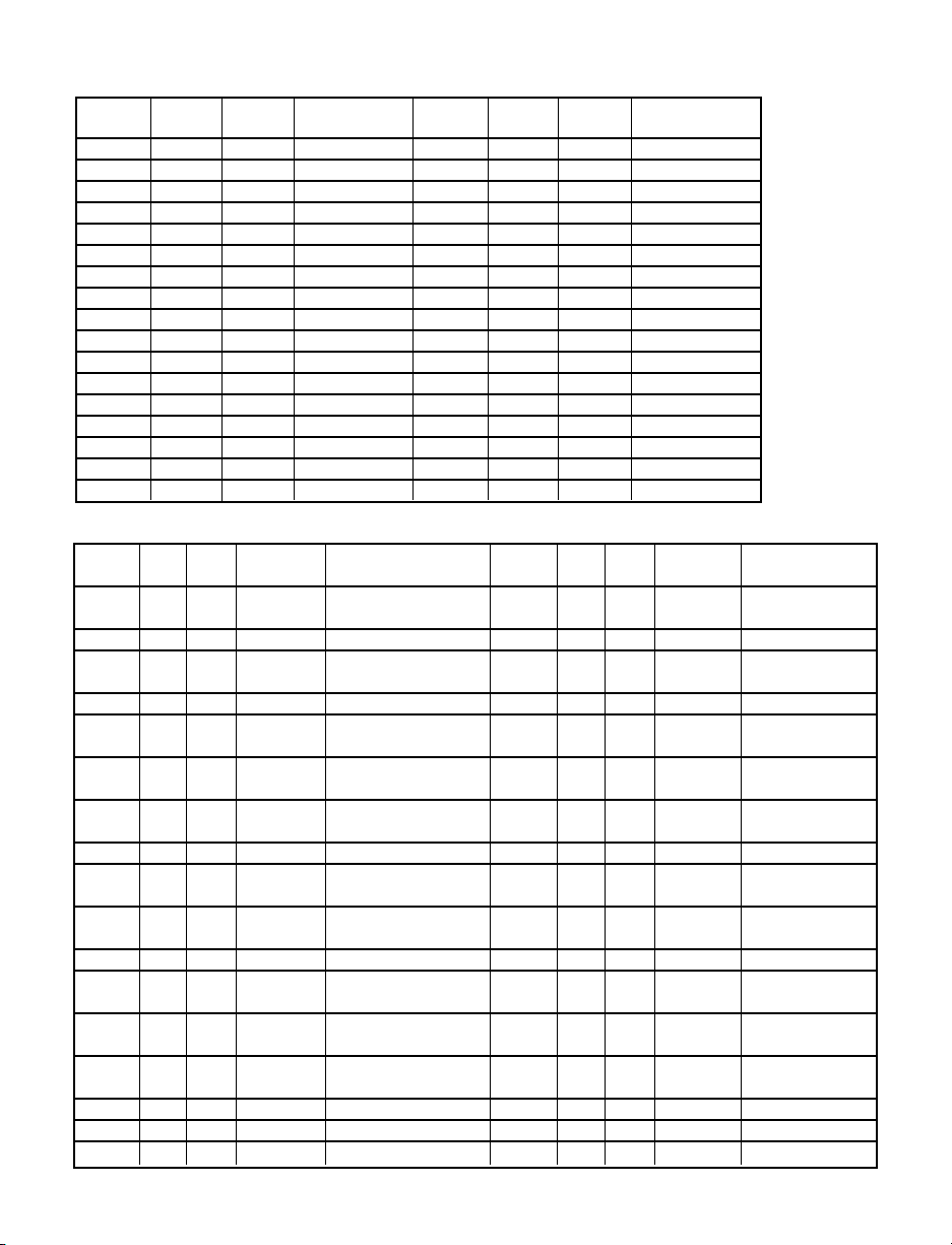
49
ASCII Chart Continued
ASCII Dec Hex Binary ASCII Dec Hex Binary
Char No parity Char No Parity
/ 47 2F 00101111 o 111 6F 01101111
0 48 30 00110000 p 112 70 01110000
1 49 31 00110001 q 113 71 01110001
2 50 32 00110010 r 114 72 01110010
3 51 33 00110011 s 115 73 01110011
4 52 34 00110100 t 116 74 01110100
5 53 35 00110101 u 117 75 01110101
6 54 36 00110110 v 118 76 01110110
7 55 37 00110111 w 119 77 01110111
8 56 38 00111000 x 120 78 01111000
9 57 39 00111001 y 121 79 01111001
: 58 3A 00111010 z 122 7A 01111010
; 59 3B 00111011 { 123 7B 01111011
< 60 3C 00111100 | 124 7C 01111100
= 61 3D 00111101 } 125 7D 01111101
> 62 3E 00111110 ~ 12 6 7E 0111111 0
? 63 3F 00111111 DEL 1 27 7F 0 1111111
ASCII Control Codes
ASCII Dec Hex Ctrl Key Definition ASCII Dec Hex Ctrl Key Definition
Char Equiv. Char Equiv.
NUL 00 00 Crtl @ Null Character DC1 17 11 Crtl Q Data Control 1
- XON
SOH 01 01 Crtl A Start of Header DC2 18 12 Crtl R Data Control 2
STX 02 02 Crtl B Start of Text DC3 19 13 Crtl S Data Control 3
- XOFF
ETX 03 03 Crtl C End of Text DC4 20 14 Crtl T Data Control 4
EOT 04 04 Crtl D End of NAK 21 15 Crtl U Negative
Transmission Acknowledge
ENQ 05 05 Crtl E Inquiry SYN 22 16 Crtl V Synchronous
Idle
ACK 06 06 Crtl F Acknowledge ETB 23 17 Crtl W End of Trans
Block
BEL 07 07 Crtl G Bell CAN 24 18 Crtl X Cancel
BS 08 08 Crtl H Back Space EM 25 19 Crtl Y End of
Medium
HT 09 09 Crtl I Horizontal SUB 26 1A Crtl Z Substitute
Tabulation
LF 10 0A Crtl J Line Feed ESC 27 1B Crtl [ Escape
VT 11 0B Crtl K Vertical FS 28 1C Crtl \ File
Tabulation Separator
FF 12 0C Crtl L Form Feed GS 29 1D Crtl ] Group
Separator
CR 13 0D Crtl M Carriage RS 30 1E Crtl | Record
Return Separator
SO 14 0E Crtl N Shift Out US 31 1F Crtl _ Unit Separator
SI 15 0F Crtl O Shift In SP 32 20 Space
DLE 16 10 Crtl P Data Link Escape
Page 54

50
APPENDIX C Example of CRC Calculation
Device address 06, read (03), starting register 0008, number of registers 0001
CRC Calculation
Function code Two byte (16 bit) Register Overflow
HB LB Bit
Load 16 bit register to all 1’s 1111 1111 1111 1111 0
First byte is address 06 0000 0110
Exclusive OR 1111 1111 1111 1001
1st shift 0111 1111 1111 1100 1
A001 1010 0000 0000 0001
Exclusive OR 1101 1111 1111 1101
2nd shift 0110 1111 1111 1110 1
A001 1010 0000 0000 0001
Exclusive OR 1100 1111 1111 1111
3rd shift 0110 0111 1111 1111 1
A001 1010 0000 0000 0001
Exclusive OR 1100 0111 1111 1110
4th shift 0110 0011 1111 1111 0
5th shift 0011 0001 1111 1111 1
A001 1010 0000 0000 0001
Exclusive OR 1001 0001 1111 111 0
6th shift 0100 1000 1111 1111 0
7th shift 0010 0100 0111 1111 1
A001 1010 0000 0000 0001
Exclusive OR 1000 0100 0111 1110
8th shift 0100 0010 0011 1111 0
Second byte Read 03 0000 0011
Exclusive OR 0100 0010 0011 1100
1st shift 0010 0001 0001 1110 0
2nd shift 0001 0000 1000 1111 0
3rd shift 0000 1000 0100 0111 1
A001 1010 0000 0000 0001
Exclusive OR 1010 1000 0100 0110
4th shift 0101 0100 0010 0011 0
5th shift 0010 1010 0001 0001 1
A001 1010 0000 0000 0001
Exclusive OR 1000 1010 0001 0000
6th shift 0100 0101 0000 1000 0
7th shift 0010 0010 1000 0100 0
8th shift 0001 0001 0100 0010 0
Third byte Starting reg. 00 0000 0000
Exclusive OR 0001 0001 0100 0010
1st shift 0000 1000 1010 0001 0
2nd shift 0000 0100 0101 0000 1
A001 1010 0000 0000 0001
Exclusive OR 1010 0100 0101 0001
3rd shift 0101 0010 0010 1000 1
A001 1010 0000 0000 0001
Exclusive OR 1111 0010 0010 1001
4th shift 0111 1001 0001 0100 1
Page 55

51
CRC Calculation Continued
Function code Two byte (16 bit) Register Overflow
HB LB Bit
A001 1010 0000 0000 0001
Exclusive OR 1101 1001 0001 0101
5th shift 0110 1100 1000 1010 1
A001 1010 0000 0000 0001
Exclusive OR 1100 1100 1000 1011
6th shift 0110 0110 0100 0101 1
A001 1010 0000 0000 0001
Exclusive OR 1100 0110 0100 0100
7th shift 0110 0011 0010 0010 0
8th shift 0011 0001 1001 0001 0
Fourth Byte 08 0000 1000
Exclusive OR 0011 0001 1001 1001
1st shift 0001 1000 1100 1100 1
A001 1010 0000 0000 0001
Exclusive OR 1011 1000 1100 1101
2nd shift 0101 1100 0110 0110 1
A001 1010 0000 0000 0001
Exclusive OR 1111 1100 0110 0111
3rd shift 0111 1110 0011 0011 1
A001 1010 0000 0000 0001
Exclusive OR 1101 1110 0011 0010
4th shift 0110 1111 0001 1001 0
5th shift 0011 0111 1000 1100 1
A001 1010 0000 0000 0001
Exclusive OR 1001 0111 1000 1101
6th shift 0100 1011 1100 0110 1
A001 1010 0000 0000 0001
Exclusive OR 1110 1011 1100 0111
7th shift 0111 0101 1110 0011 1
A001 1010 0000 0000 0001
Exclusive OR 1101 0101 1110 0010
8th shift 0110 1010 1111 0001 0
Fifth Byte 00 0000 0000
Exclusive OR 0110 1010 1111 0001
1st shift 0011 0101 0111 1000 1
A001 1010 0000 0000 0001
Exclusive OR 1001 0101 0111 1001
2nd shift 0100 1010 1011 1100 1
A001 1010 0000 0000 0001
Exclusive OR 1110 1010 1011 1101
3rd shift 0111 0101 0101 1110 1
A001 1010 0000 0000 0001
Exclusive OR 1101 0101 0101 1111
4th shift 0110 1010 1010 1111 1
A001 1010 0000 0000 0001
Exclusive OR 1100 1010 1010 1110
5th shift 0110 0101 0101 0111 0
6th shift 0011 0010 1010 1011 1
Page 56
CRC Calculation Continued
Function code Two byte (16 bit) Register Overflow
HB LB Bit
A001 1010 0000 0000 0001
Exclusive OR 1001 0010 1010 1010
7th shift 0100 1001 0101 0101 0
8th shift 0010 0100 1010 1010 1
A001 1010 0000 0000 0001
Exclusive OR 1000 0100 1010 1011
Sixth Byte 01 0000 0001
Exclusive OR 1000 0100 1010 1010
1st shift 0100 0010 0101 0101 0
2nd shift 0010 0001 0010 1010 1
A001 1010 0000 0000 0001
Exclusive OR 1000 0001 0010 1011
3rd shift 0100 0000 1001 0101 1
A001 1010 0000 0000 0001
Exclusive OR 1110 0000 1001 0100
4th shift 0111 0000 0100 1010 0
5th shift 0011 1000 0010 0101 0
6th shift 0001 1100 0001 0010 1
A001 1010 0000 0000 0001
Exclusive OR 1011 1100 0001 0011
7th shift 0101 1110 0000 1001 1
A001 1010 0000 0000 0001
Exclusive OR 1111 1110 0000 1000
8th shift 0111 1111 0000 0100 0
CRC code 7F04
Transmitted Message:
DEVICE FUNCTION STARTING NUMBER OF CRC
ADDRESS CODE REGISTER REGISTERS
06 03 00 08 00 01 04 7F
52
Page 57

Example of CRC calculation in “C” language
This subroutine used to do CRC calculation
#define POLY 0xA001;
unsigned int crc_calculation (unsigned char *start_string, unsigned char number_byte)
{
unsigned int crc;
unsigned char bit_counter;
unsigned char *data_pointer;
data_pointer= start_string;
crc = 0xffff; // Initialize crc
while (number_byte>0)
{
crc ^= data_pointer // crc XOR with data
bit_counter=0; // reset counter
while (bit_counter < 8)
{
if (crc & 0x0001)
{
crc >>= 1; // shift to the right 1 position
crc ^= POLY; // crc XOR with POLY
}
else
{
crc >>=1; // shift to the right 1 position
}
bit_counter++; // increase counter
}
number_byte--; // adjust byte counter
}
return (crc); // final result of crc
}
53
Page 58

APPROVAL INFORMATION
1. Electromagnetic Compatibility (EMC)
This device comforms with requirements of EMC Directive 89/336/EEC,
amended by 93/68/EEC. This instrument complies with the following EMC
Immunity Standards as tested per EN 50082-2, 1995 (Industrial environment)
Phenomena Test Specification Basic Standard
Electrostatic +/- 4 kV contact discharge IEC 1000-4-2
Discharge +/- 8 kV air discharge Performance
Criteria B
Radio Frequency 27 - 1000 MHz IEC 1000-4-3
electromagnetic 10 V/m Performance
field. 80% AM (1 KHz) Criteria A
Radio Frequency 900 MHz IEC 1000-4-3
electromagnetic field. 10 V/m Performance
Pulse modulated. 50% Duty cycle @ 200 Hz Criteria A
Fast Transients +/- 2 kV (ac mains) IEC 1000-4-4
+/- 1 kV (dc, signal I/O) Performance
5/50 ns Tr/Th, 5 KHz rep. freq. Criteria B
Radio Frequency 0.15 - 80 MHz IEC 1000-4-6
conducted 10 V/m Performance
80% AM (1 KHz) Criteria A
This instrument complies with the following EMC Emission Standards as
tested per EN 50081-1, 1992 (Residential, Commercial and Light Industrial)
Phenomena Frequency Limits Basic
Range Standard
Radiated 30-230 MHz 30 dB_V/m at 10 m CISPR 22
Emission 230-1000 MHz 37 dB_V/m at 10 m Class B
quasi peak
Conducted 0.15-0.5 MHz 66-56 dB_V quasi peak CISPR 22
Emission 0.5-5 MHz 56 dB_V quasi peak Class B
5-30 MHz 60 dB_V quasi peak
2.Safety
This device conforms with Low Voltage Directive 73/23/EEC, amended by 93/68/EEC.
The following LVD requirements have been met to comply with EN 61010-1, 1993
(Electrical equipment for measurement, control and laboratory use)
1. Pollution Degree 2
2. Installation Category II
3. Double Insulation
4. Class I Equipment (Units with 100-240 Vac Power)
54
Page 59

WARRANTY/DISCLAIMER
OMEGA ENGINEERING, INC. warrants this unit to be free of defects in materials and workmanship for a
period of 61 months from date of purchase. OMEGA’s WARRANTY adds an additional one (1) month grace
period to the normal five (5) year product warranty to cover handling and shipping time. This ensures
that OMEGA’s customers receive maximum coverage on each product.
If the unit malfunctions, it must be returned to the factory for evaluation. OMEGA’s Customer Service
Department will issue an Authorized Return (AR) number immediately upon phone or written request.
Upon examination by OMEGA, if the unit is found to be defective, it will be repaired or replaced at no
charge. OMEGA’s WARRANTY does not apply to defects resulting from any action of the purchaser,
including but not limited to mishandling, improper interfacing, operation outside of design limits,
improper repair, or unauthorized modification. This WARRANTY is VOID if the unit shows evidence of
having been tampered with or shows evidence of having been damaged as a result of excessive corrosion;
or current, heat, moisture or vibration; improper specification; misapplication; misuse or other operating
conditions outside of OMEGA’s control. Components in which wear is not warranted, include but are not
limited to contact points, fuses, and triacs.
OMEGA is pleased to offer suggestions on the use of its various products. However,
OMEGA neither assumes responsibility for any omissions or errors nor assumes liability for
any damages that result from the use of its products in accordance with information provided
by OMEGA, either verbal or written. OMEGA warrants only that the parts manufactured by the
company will be as specified and free of defects. OMEGA MAKES NO OTHER WARRANTIES OR
REPRESENTATIONS OF ANY KIND WHATSOEVER, EXPRESSED OR IMPLIED, EXCEPT THAT OF
TITLE, AND ALL IMPLIED WARRANTIES INCLUDING ANY WARRANTY OF MERCHANTABILITY
AND FITNESS FOR A PARTICULAR PURPOSE ARE HEREBY DISCLAIMED. LIMITATION OF
LIABILITY: The remedies of purchaser set forth herein are exclusive, and the total liability of
OMEGA with respect to this order, whether based on contract, warranty, negligence,
indemnification, strict liability or otherwise, shall not exceed the purchase price of the
component upon which liability is based. In no event shall OMEGA be liable for
consequential, incidental or special damages.
CONDITIONS: Equipment sold by OMEGA is not intended to be used, nor shall it be used: (1) as a “Basic
Component” under 10 CFR 21 (NRC), used in or with any nuclear installation or activity; or (2) in medical
applications or used on humans. Should any Product(s) be used in or with any nuclear installation or
activity, medical application, used on humans, or misused in any way, OMEGA assumes no responsibility
as set forth in our basic WARRANTY/DISCLAIMER language, and, additionally, purchaser will indemnify
OMEGA and hold OMEGA harmless from any liability or damage whatsoever arising out of the use of the
Product(s) in such a manner.
RETURN REQUESTS/INQUIRIES
Direct all warranty and repair requests/inquiries to the OMEGA Customer Service Department. BEFORE
RETURNING ANY PRODUCT(S) TO OMEGA, PURCHASER MUST OBTAIN AN AUTHORIZED RETURN (AR)
NUMBER FROM OMEGA’S CUSTOMER SERVICE DEPARTMENT (IN ORDER TO AVOID PROCESSING
DELAYS). The assigned AR number should then be marked on the outside of the return package and on any
correspondence.
The purchaser is responsible for shipping charges, freight, insurance and proper packaging to prevent
breakage in transit.
FOR WARRANTY RETURNS, please have the
following information available BEFORE contacting
OMEGA:
1. Purchase Order number under which the product
was PURCHASED,
2. Model and serial number of the product under
warranty, and
3. Repair instructions and/or specific problems
relative to the product.
OMEGA’s policy is to make running changes, not model changes, whenever an improvement is possible. This affords our
customers the latest in technology and engineering.
OMEGA is a trademark of OMEGA ENGINEERING, INC.
© Copyright 2018 OMEGA ENGINEERING, INC. All rights reserved. This document may not be copied, photocopied,
reproduced, translated, or reduced to any electronic medium or machine-readable form, in whole or in part, without the prior
written consent of OMEGA ENGINEERING, INC.
FOR NON-WARRANTY REPAIRS, consult
OMEGA for current repair charges. Have
the following information available BEFORE
contacting OMEGA:
1. Purchase Order number to cover the COST
of the repair,
2. Model and serial number of the product, and
3. Repair instructions and/or specific problems
relative to the product.
Page 60

Where Do I Find Everything I Need for
Process Measurement and Control?
OMEGA…Of Course!
Shop online at omega.com
TEMPERATURE
MU
Thermocouple, RTD & Thermistor Probes, Connectors,
Panels & Assemblies
MU
Wire: Thermocouple, RTD & Thermistor
MU
Calibrators & Ice Point References
MU
Recorders, Controllers & Process Monitors
MU
Infrared Pyrometers
PRESSURE, STRAIN AND FORCE
MU
Transducers & Strain Gages
MU
Load Cells & Pressure Gages
MU
Displacement Transducers
MU
Instrumentation & Accessories
FLOW/LEVEL
MU
Rotameters, Gas Mass Flowmeters & Flow Computers
MU
Air Velocity Indicators
MU
Turbine/Paddlewheel Systems
MU
Totalizers & Batch Controllers
pH/CONDUCTIVITY
MU
pH Electrodes, Testers & Accessories
MU
Benchtop/Laboratory Meters
MU
Controllers, Calibrators, Simulators & Pumps
MU
Industrial pH & Conductivity Equipment
DATA ACQUISITION
MU
Communications-Based Acquisition Systems
MU
Data Logging Systems
MU
Wireless Sensors, Transmitters, & Receivers
MU
Signal Conditioners
MU
Data Acquisition Software
HEATERS
MU
Heating Cable
MU
Cartridge & Strip Heaters
MU
Immersion & Band Heaters
MU
Flexible Heaters
MU
Laboratory Heaters
ENVIRONMENTAL
MONITORING AND CONTROL
MU
Metering & Control Instrumentation
MU
Refractometers
MU
Pumps & Tubing
MU
Air, Soil & Water Monitors
MU
Industrial Water & Wastewater Treatment
MU
pH, Conductivity & Dissolved Oxygen Instruments
M3730/0818
 Loading...