

Omega ILD44-UTP User Manual

iLD24-UTP, iLD44-UTP Big Display
Universal Temperature & Process
Controller Manual
User’s Guide
www.omega.com
e-mail: info@omega.com
iSeries info: www.omega.com/specs/iSeries
Shop on line at
®
®

It is the policy of OMEGA to comply with all worldwide safety and EMC/EMI regulations that apply.
OMEGA is constantly pursuing certification of its products to the European New Approach Directives. OMEGA will add the
CE mark to every appropriate device upon certification.
The information contained in this document is believed to be correct but OMEGA Engineering, Inc. accepts no liability for
any errors it contains, and reserves the right to alter specifications without notice.
WARNING: These products are not designed for use in, and should not be used for, patient connected applications.
!
This device is marked with the international caution symbol. It is important to read the Setup Guide before
installing or commissioning this device as it contains important information relating to safety and EMC.
®
®
OMEGAnet® On-Line Service
www.omega.com
Internet e-mail
info@omega.com
Servicing North America:
USA: One Omega Drive, P.O. Box 4047
ISO 9001 Certified Stamford CT 06907-0047
TEL: (203) 359-1660 FAX: (203) 359-7700
e-mail: info@omega.com
Canada: 976 Bergar
Laval (Quebec) H7L 5A1
TEL: (514) 856-6928 FAX: (514) 856-6886
e-mail: info@omega.ca
For immediate technical or application assistance:
USA and Canada: Sales Service: 1-800-826-6342 / 1-800-TC-OMEGA
Customer Service: 1-800-622-2378 / 1-800-622-BEST
Engineering Service: 1-800-872-9436 / 1-800-USA-WHEN
Mexico and TEL: (001)800-TC-OMEGA® FAX: (001) 203-359-7807
Latin America: En Español: (001) 203-359-7803
e-mail: espanol@omega.com
®
®
®
Servicing Europe:
Benelux: Postbus 8034, 1180 LA Amstelveen, The Netherlands
TEL: +31 20 3472121 FAX: +31 20 6434643
Toll Free in Benelux: 0800 0993344
e-mail: sales@omegaeng.nl
Czech Republic: Frystatska 184, 733 01 Karviná
TEL: +420 59 6311899 FAX: +420 59 6311114
e-mail: info@omegashop.cz
France: 11, rue Jacques Cartier, 78280 Guyancourt
TEL: +33 1 61 37 29 00 FAX: +33 1 30 57 54 27
Toll Free in France: 0800 466 342
Germany/Austria: Daimlerstrasse 26, D-75392 Deckenpfronn, Germany
TEL: +49 7056 9398-0 FAX: +49 7056 9398-29
Toll Free in Germany: 0800 639 7678
e-mail: info@omega.de
United Kingdom: One Omega Drive
ISO 9002 Certified River Bend Technology Centre
Northbank, Irlam Manchester M44 5BD United Kingdom
TEL: +44 161 777 6611 FAX: +44 161 777 6622
Toll Free in England: 0800 488 488
e-mail: sales@omega.co.uk
e-mail: sales@omega.fr

TABLE OF CONTENTS
Part 1: Introduction............................................................................................2
1.1 Description .................................................................................2
1.2 Safety Considerations ...............................................................3
1.3 Before You Begin .......................................................................4
Part 2: Setup.......................................................................................................5
2.1 Mounting .....................................................................................5
2.2 Rear Panel Connections............................................................7
2.3 Electrical Installation .................................................................8
2.3.1 Power Connections........................................................8
2.3.2 Thermocouple - Input Connection................................9
2.3.3 Two / Three / Four Wire RTD-Hookups.......................10
2.3.4 Process Current - Wiring Hookup...............................11
2.3.5 Process Voltage - Wiring Hookup ...............................11
2.3.6 Wiring Outputs - Wiring Hookup.................................12
Part 3: Operation: Configuration Mode .........................................................14
3.1 Introduction ..............................................................................14
Turning your Instrument On for the First Time
Buttons Functions in Configuration Mode
3.2 Menu Configuration ................................................................15
3.2.1 ID Number .....................................................................16
3.2.2 Setpoints .......................................................................17
3.2.3 Configuration Menu ....................................................18
3.2.4 Input Type Menu ...........................................................18
Input Type (Thermocouple) ........................................19
Input Type (RTD)...........................................................20
Input Type (Process) ...................................................21
3.2.5 Reading Configuration Menu .....................................21
3.2.6 Alarm 1 Menu ...............................................................25
3.2.7 Analog Output (Retransmission) Menu......................29
3.2.8 Alarm 2 Menu................................................................32
3.2.9 Loop Break Time Menu / Field Calibration.................33
3.2.10 Output 1 Menu ..............................................................36
3.2.11 Output 2 Menu ..............................................................43
3.2.12 Ramp and Soak Menu ..................................................46
3.2.13 ID Code Menu ...............................................................48
3.2.14 Communication (Options) Menu.................................50
3.2.15 Display Color Selection Menu.....................................56
Part 4: Specifications ......................................................................................59
Part 5: Factory Preset Values.........................................................................62
CE APPROVAL INFORMATION.......................................................................65
i

LIST OF FIGURES:
Figure 2.1 Mounting ...............................................................................................5
Figure 2.2 Rear Panel Power and Output Connector Labels..............................7
Figure 2.3 Rear Panel Input Connector Labels....................................................7
Figure 2.4 Main Power Connections.....................................................................8
Figure 2.5 Inside Cover Rear View........................................................................8
Figure 2.6 Thermocouple Wiring Hookup ............................................................9
Figure 2.7 Two/Three/Four-wire RTD
a) RTD-1000 ohm and 500 ohm Wiring Hookup ............................10
b) RTD-100 ohm Wiring Hookup .....................................................10
Figure 2.8 Process Current Wiring Hookup
(Internal and External Excitation)......................................................11
Figure 2.9 Process Voltage Wiring Hookup
a) Without Sensor Excitation ..........................................................11
b) With Sensor Excitation ................................................................11
Figure 2.10 Output Connections:
a) Mechanical Relay and SSR Outputs – Wiring Hook up............12
b) Pulse and Analog Outputs – Wiring Hook up............................12
Figure 2.11 Communication Output:
a) RS-232 Output – Wiring Hook up ...............................................12
b) RS-485 Output – Wiring Hook up ...............................................12
Figure 2.12 Excitation Output................................................................................13
Figure 2.13 Snubber Circuits Wiring Hookup ......................................................13
Figure 3.1 Flow Chart for ID and Setpoints........................................................15
Figure 3.2 Flow Chart for Configuration Menu ..................................................18
Figure 3.3 Flow Chart for Input Type Menu........................................................18
Figure 3.4 Flow Chart for Reading Configuration .............................................21
Figure 3.5 Flow Chart for Alarm 1.......................................................................25
Figure 3.6 Flow Chart for Analog Output (Retransmission).............................29
Figure 3.7 Flow Chart for Alarm 2.......................................................................32
Figure 3.8 Flow Chart for Loop Break Time / Field Calibration........................33
Figure 3.9 Flow Chart for Output 1 .....................................................................36
Figure 3.10 Flow Chart for Output 2 .....................................................................43
Figure 3.11 Flow Chart for Ramp and Soak .........................................................46
Figure 3.12 Flow Chart for ID Code.......................................................................48
Figure 3.13 Flow Chart for Communication Option ............................................50
Figure 3.14 Flow Chart for Display Color Selection............................................56
LIST OF TABLES:
Table 2.1 Front Panel Annunciators....................................................................6
Table 2.2 Rear Panel Connector..........................................................................7
Table 2.3 TC Wire Color Chart .............................................................................9
Table 3.1 Button Function in Configuration Mode...........................................14
Table 3.2 Conversion Table................................................................................24
Table 4.1 Input Properties..................................................................................61
Table 5.1 Factory Preset Values........................................................................62
ii
NOTES, WARNINGS and CAUTIONS
Information that is especially important to note is identified by following labels:
• NOTE
• WARNING or CAUTION
• IMPORTANT
• TIP
NOTE: Provides you with information that is important to successfully
setup and use the Programmable Digital Meter.
CAUTION or WARNING: Tells you about the risk of electrical shock.
CAUTION, WARNING or IMPORTANT: Tells you of circumstances or
practices that can effect the instrument’s functionality and must refer
to accompanying documents.
TIP: Provides you helpful hints.
1

PART 1
INTRODUCTION
1.1 Description
This device can be purchased as monitor (read process value only) or as
a controller.
• The iLD Big Display controller offers unparalleled flexibility in process
measurement. Each unit allows the user to select the input type, from
10 thermocouple types (J, K, T, E, R, S, B, C, N and J DIN), Pt RTDs (100,
500 or 1000 Ω, with either 385 or 392 curve), DC voltage, or DC current.
The voltage/current inputs are fully scalable to virtually all engineering units,
with selectable decimal point, perfect for use with pressure, flow or other
process input.
• The temperature control can be achieved by using on/off or PID heat/cool
control strategy. Control can be optimized with an auto tune feature. The
instrument offers a ramp to setpoint with timed soak period before switching
off the output.
• The iLD Big Display device features a large, three color programmable
display with capability to change a color every time the Alarm is triggered.
The standard features include dual outputs with relay, SSR, dc pulse, analog
voltage or current. Options include programmable RS-232 or RS-485 serial
communication and excitation. Analog Output is fully scalable and may be
configured as a proportional controller or retransmission to follow your
display. Universal power supply accepts 100 to 240 Vac.
2
1.2 Safety Considerations
This device is marked with the international caution symbol. It is important
to read this manual before installing or commissioning this device as it
contains important information relating to Safety and EMC
(Electromagnetic Compatibility).
This instrument is protected in accordance with Class I of EN 61010
(110/240 AC power connections). Installation of this instrument should be
done by qualified personnel. In order to ensure safe operation, the
following instructions should be followed.
This instrument has no power-on switch. An external switch or circuitbreaker shall be included in the building installation as a disconnecting
device. It shall be marked to indicate this function, and it shall be in close
proximity to the equipment within easy reach of the operator. The switch or
circuit-breaker shall meet the relevant requirements of IEC 947–1 and
IEC 947-3 (International Electrotechnical Commission). The switch shall
not be incorporated in the main supply cord.
Furthermore, to provide protection against excessive energy being drawn
from the main supply in case of a fault in the equipment, an overcurrent
protection device shall be installed.
• Do not exceed voltage rating on the label located on the top of the
instrument housing.
• Always disconnect power before changing signal and power
connections.
• Do not use this instrument on a work bench without its case for safety
reasons.
• Do not operate this instrument in flammable or explosive atmospheres.
• Do not expose this instrument to rain or moisture.
• Unit mounting should allow for adequate ventilation to ensure
instrument does not exceed operating temperature rating.
• Use electrical wires with adequate size to handle mechanical strain
and power requirements. Install without exposing bare wire outside the
connector to minimize electrical shock hazards.
EMC Considerations
• Whenever EMC is an issue, always use shielded cables.
• Never run signal and power wires in the same conduit.
• Use signal wire connections with twisted-pair cables.
• Install Ferrite Bead(s) on signal wires close to the instrument if EMC
problems persist.
Failure to follow all instructions and warnings may result in injury!
3

1.3 Before You Begin
Inspecting Your Shipment:
Remove the packing slip and verify that you have received everything
listed. Inspect the container and equipment for signs of damage as soon
as you receive the shipment. Note any evidence of rough handling in
transit. Immediately report any damage to the shipping agent. The carrier
will not honor damage claims unless all shipping material is saved for
inspection. After examining and removing the contents, save the packing
material and carton in the event reshipment is necessary.
Customer Service:
If you need assistance, please call the nearest Customer Service
Department, listed in this manual.
Manuals, Software:
The latest Operation and Communication Manual as well as free
configuration software and ActiveX controls are available from
the
website listed in this manual or on the CD-ROM enclosed with your
shipment
.
For first-time users: Refer to the QuickStart Manual for basic operation
and set-up instructions.
If you have the Serial Communications/Ethernet Option you can easily
configure the controller on your computer or on-line.
To Disable Outputs:
Standby Mode is useful during setup of the instrument or when
maintenance of the system is necessary. When the instrument is in
standby, it remains in the ready condition but all outputs are disabled.
This allows the system to remain powered and ready to go.
When the instrument is in "RUN" Mode, push d twice to disable all
outputs and alarms. It is now in "STANDBY" Mode. Push d once more
to resume "RUN" Mode.
PUSH d TWICE to disable the system during an EMERGENCY.
To Reset the Meter:
When the controller is in the "MENU" Mode, push c once to direct
controller one step backward of the top menu item.
Push c twice to reset controller, prior to resuming "Run" Mode except
after "Alarms", that will go to the "Run" Mode without resetting the
controller.
4
5
PART 2
SETUP
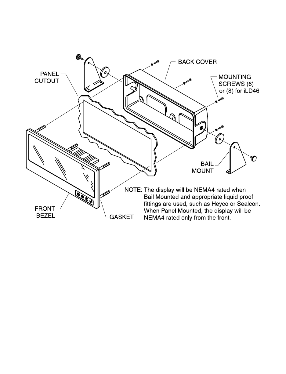
2.1 Mounting
Figure 2.1 Mounting

Mounting iLD Big Display Through Panel:
1. Using the panel cutout diagram shown in your Quick Start Manual, cut
an opening in the panel.
2. Remove six (or eight) screws at the back of iLD Big Display to remove
back cover.
3. Insert the unit into the opening from the front of the panel so the gasket
seals between the bezel and the front of the panel.
4. Pass all wiring through customer drilled holes in back cover and
connect wiring to terminal blocks.
5. Align back cover to iLD Big Display and reinstall screws.
Mounting iLD Big Display on Bail:
1. Remove six (or eight) screws at the back of iLD Big Display to remove
back cover.
2. Pass all wiring through customer drilled holes in back cover and
connect wiring to terminal blocks.
3. Align back cover to iLD Big Display and reinstall screws.
4. Mark the location of mounting screws on the flat surface.
5. Be sure to leave enough room around the bail to allow for removal and
rotation of the display.
6. The display can be rotated for the best viewing angle.
Table 2.1 Front Panel Annunciators
1 Output 1/Setpoint 1/ Alarm 1 indicator
2 Output 2/Setpoint 2/ Alarm 2 indicator
°C °C unit indicator
°F °F unit indicator
a
Changes display to Configuration Mode
and advances through menu items*
b
Used in Program Mode and Peak Recall*
c
Used in Program Mode and Valley Recall*
d
Accesses submenus in Configuration Mode
and stores selected values*
* See Part 3 Operation: Configuration Mode
6
7
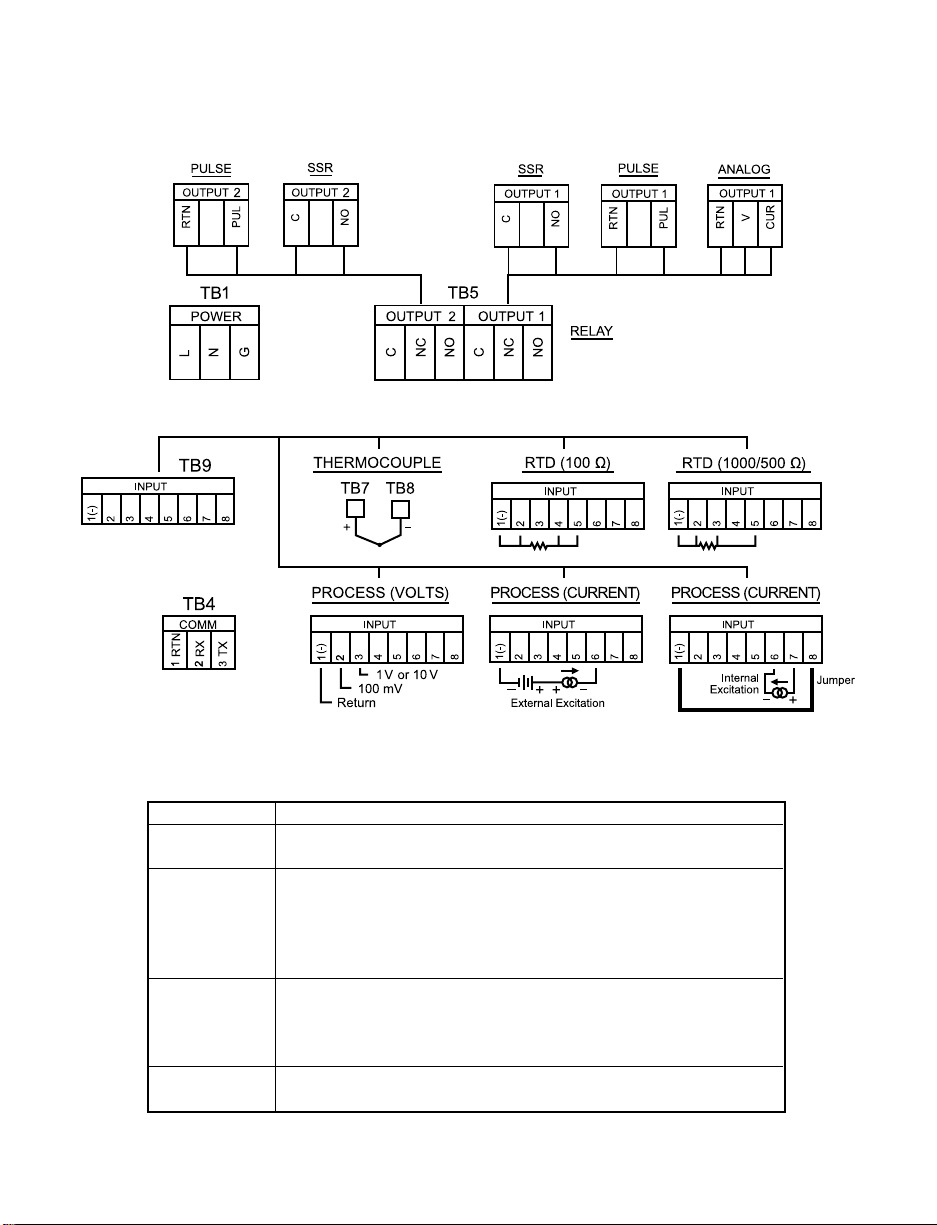
2.2 Rear Panel Connections
The rear panel connections are shown in Figures 2.2 and 2.3.
Figure 2.2 Rear Panel Power and Output Connections
Figure 2.3 Rear Panel Input Connections
Table 2.2 Rear Panel Connector
POWER AC Power Connector: All models
INPUT Input Connector: TB7 & TB8 for TC models
TB9 for PR (Process) & RTD models
OUTPUT 1 Based on one of the following models:
Relay SPDT
Solid State Relay
Pulse
Analog Output (Voltage and Current)
OUTPUT 2 Based on one of the following models:
Relay SPDT
Solid State Relay
Pulse
OPTION Based on one of the following models:
RS-232C or RS-485
213 213 546 546 546
213 213546
8
2.3 Electrical Installation
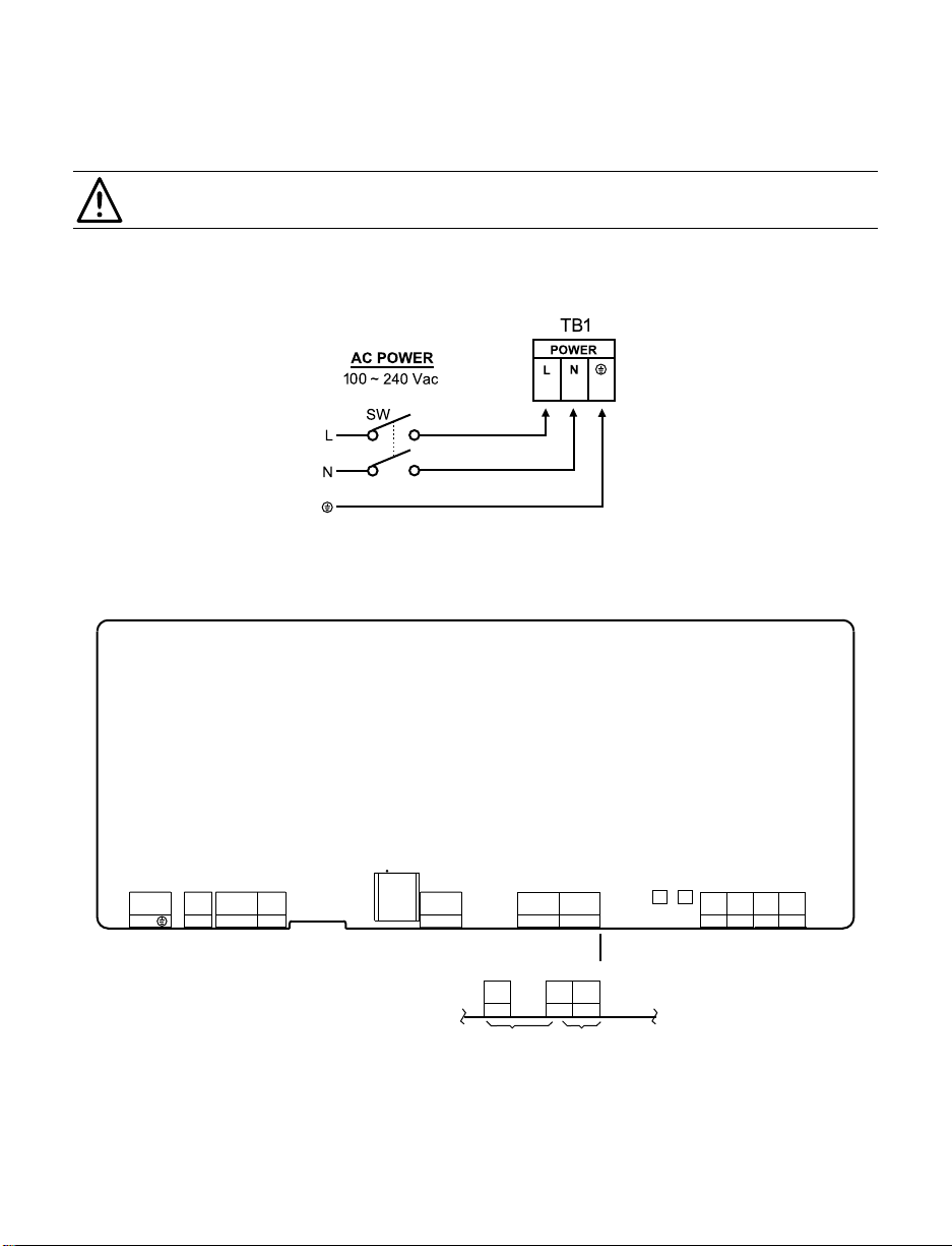
2.3.1 Power Connections
Caution: Do not connect power to your device until you have completed all
input and output connections. Failure to do so may result in injury!
Connect the main power connections as shown in Figure 2.4.
Figure 2.4 Main Power Connections
Figure 2.5 Inside Cover Rear View
AC
PWR
TB1
DC
PWR
REMOTE
PROGRAMMER
TB2 TB3
1 2 3 1 2 1 2 3 4 5
L N
+ -
1 2 31 2 3
TB5TB4
4 5 6
TB9
TB7 TB8
1 2
3 4 5 6 7 8
PJ3
1 2 3 4 5 6
1 3 5
2 4 6
+ -
COMMUNICATION OUTPUTS T/C INPUT INPUTS
OUTPUT2 OUTPUT1
RTN
Rx Tx
1 2
TB5A TB5CTB5B
3 4 5 6
iLD24 OUTPUTS
OUTPUT2 OUTPUT1
3
2
1
9
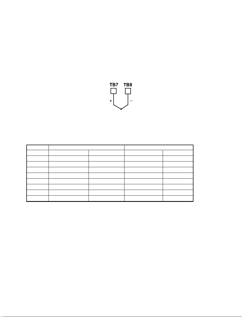
2.3.2 Thermocouple
The figure below shows the wiring hookup for any thermocouple type. For
example, for Type K hookup, connect the yellow wire to the TB7(+) terminal and
the red wire to the TB8(-) terminal.
When configuring your controller, select Thermocouple and Thermocouple
Type in the Input Type menu (see Part 3).
Figure 2.6 Thermocouple Wiring Hookup
TYPE Input Connector Jacket (external insulation)
Terminal 8 (-) Terminal 7 (+) Extension Grade
J Red White dark-Brown Black
K Red Yellow dark-Brown Yellow
T Red Blue dark-Brown Blue
E Red Purple dark-Brown Purple
N Red Orange dark-Brown Brown
R Red Black - Green
S Red Black - Green
B Red Gray - Black
Table 2.3 TC Wire Color Chart
10
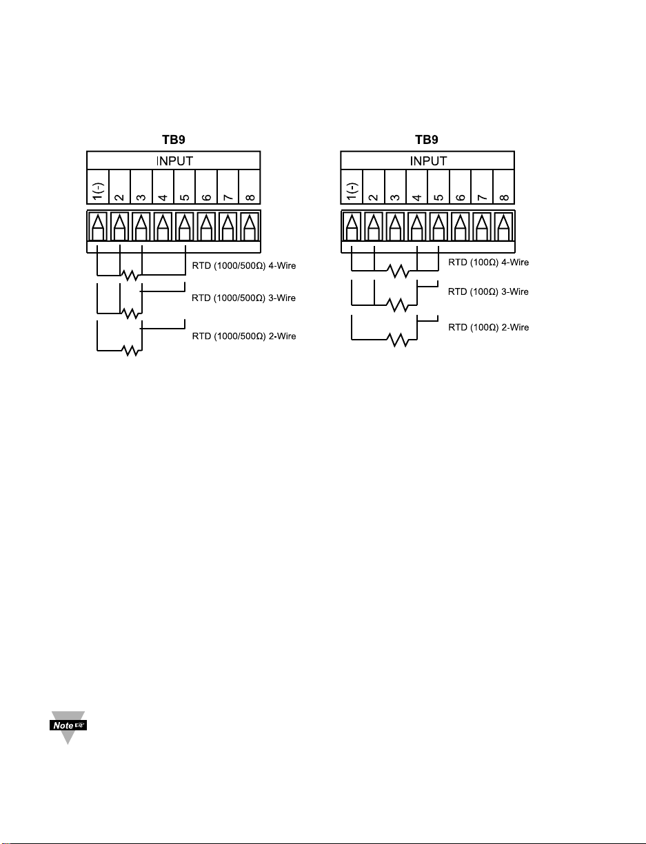
2.3.3 Two/Three/Four-Wire RTD
The figures below show the input connections and input connector jumpers
(shown in bold lines) required to hookup a 2-, 3- or 4-wire RTD.
Figure 2.7
a)
RTD-1000 ohm and 500 ohm b) RTD-100 ohm Wiring Hookup
Wiring Hookup
The two-wire connection is simplest method, but does not compensate for
lead-wire temperature change and often requires calibration to cancel lead-wire
resistance offset.
The three-wire connection works best with RTD leads closely equal in
resistance. The device measures the RTD, plus upper and lower lead drop
voltage and the subtracts twice the measured drop in the lower supply current
lead producing excellent lead-resistance cancellation for balanced
measurements.
The four-wire RTD hookup is applicable to unbalanced lead resistance and
enables the device to measure and subtract the lead voltage, which produces
the best lead-resistance cancellation.
When configuring your controller, select RTD type and RTD value in the
Input Type menu (see Part 3).
If the input wires of the meter get disconnected or broken, it will display
+OPN “Input (+) Open” message except in case of 500/1000 Ω 2-wire
RTD. In this case the display shows -OPN “Input (-) Open” message. For
safety purpose you may want to set up your alarm to be triggered when
input is open. See Alarm 1 & 2 chapters for details.
11
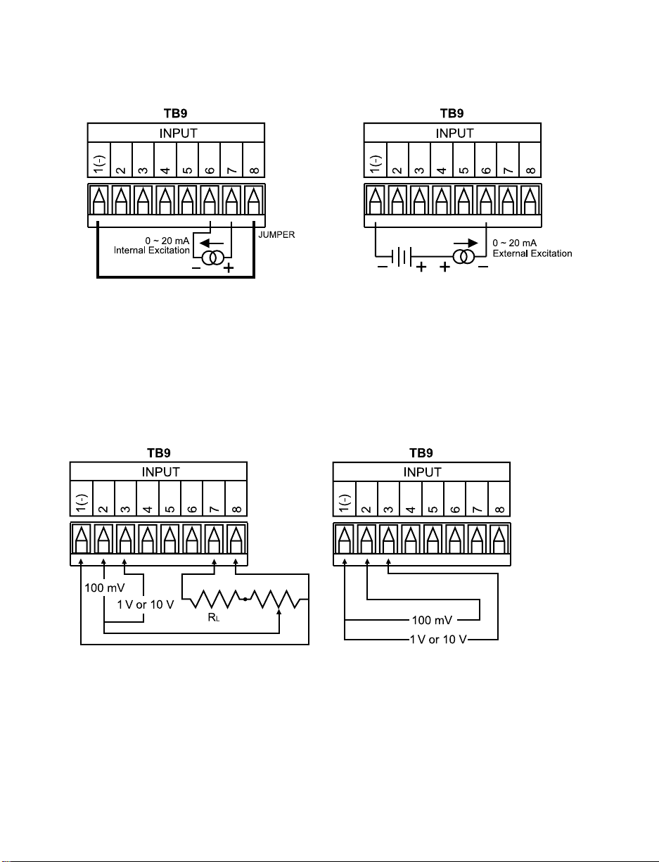
2.3.4 Process Current
The figure below shows the wiring hookup for Process Current 0 – 20 mA.
Figure 2.8 Process Current Wiring Hookup
(Internal and External Excitation)
When configuring your instrument, select Process Type in the Input Type Menu (see Part 3).
2.3.5 Process Voltage
The figure below shows the wiring hookup for Process Voltage 0 – 100 mV,
0 – 1 V, 0 – 10 V.
Figure 2.9
a) Process Voltage Wiring Hookup b) Process Voltage Wiring Hookup
with Sensor Excitation without Sensor Excitation
RL - Voltage limiting resistor, which allows conversion of the 24 Vdc internal excitation voltage to
the appropriate process input value. For instance: if the potentiometer value is equal to 10 kΩ, the
minimum R
L is 14 kΩ for 10 V process input.
When configuring your instrument, select Process Type in the Input Type Menu (see Part 3).
12
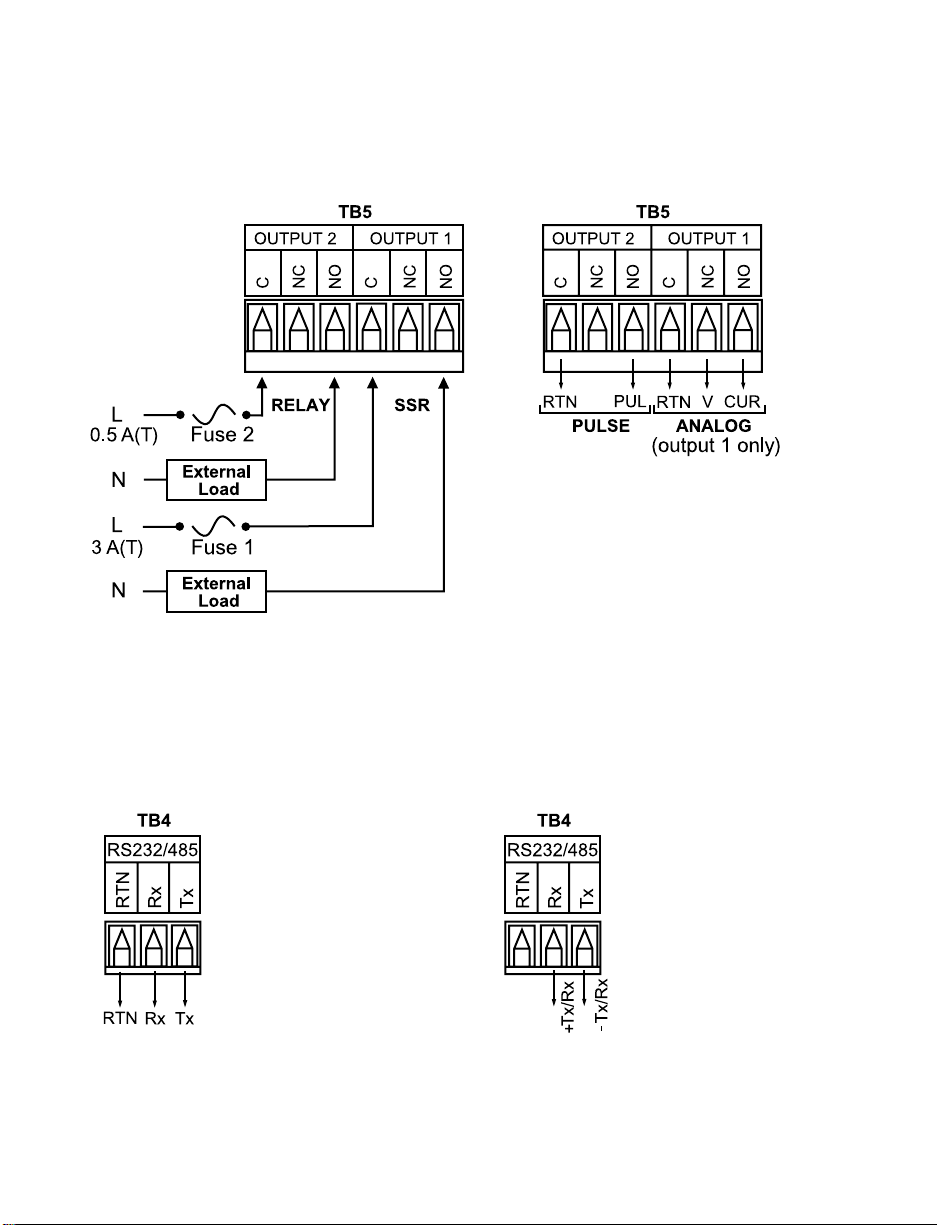
2.3.6 Wiring Outputs
This meter has two, factory installed, outputs. The SPDT Mechanical Relay, SPST
Solid State Relay, Pulse and Analog Output Connection are shown below.
Figure 2.10
a) Mechanical Relay and SSR b) Pulse and Analog
Outputs Wiring Hookup Outputs Wiring Hookup
This device may have a programmable communication output. The RS-232 and
RS-485 Output Connection are shown below.
Figure 2.11
a) RS-232 Output Wiring Hookup b) RS-485 Output Wiring Hookup
165432165432
11
13
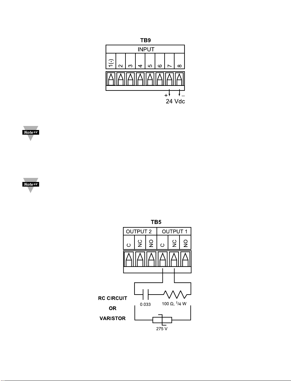
This device may also have an excitation output.
Figure 2.12 Excitation Output
Excitation is not available if communication option is installed.
This device has snubber circuits designed to protect the contacts of the
mechanical relays when it switches to inductive loads (i.e. solenoids,
relays). These snubbers are internally connected between the Common
(C) and Normally Open (NO) relay contacts of Output 1 and Output 2.
If you have an inductive load connected between Common (C) and
Normally Closed (NC) contacts of the mechanical relays and you want to
protect them from the rush current during the switching period, you have
to connect an external snubber circuit between Common (C) and
Normally Closed (NC) contacts as indicated in the figure below.
Figure 2.13 Snubber Circuits Wiring Hookup
165432

14
PART 3
OPERATION: Configuration Mode
3.1 Introduction
The instrument has two different modes of operation. The first, Run Mode, is
used to display values for the Process Variable, and to display or clear Peak
and Valley values. The other mode, Menu Configuration Mode, is used to
navigate through the menu options and configure the controller. Part 3 of this
manual will explain the Menu Configuration Mode. For your instrument to
operate properly, the user must first "program" or configure the menu options.
Turning your Controller On for the First Time
The device becomes active as soon as it is connected to a power source. It
has no On or Off switch. The device at first momentarily shows the software
version number, followed by reset
RST
, and then proceeds to the Run Mode.
Table 3.1 Button Function in Configuration Mode
• To enter the Menu, the user must first press abutton.
• Use this button to advance/navigate to the next menu item. The user can
navigate through all the top level menus by pressing a.
• While a parameter is being modified, press ato escape without saving
the parameter.
• Press the up bbutton to scroll through “flashing” selections. When a
numerical value is displayed press this key to increase value of a
parameter that is currently being modified.
• Holding the bbutton down for approximately 3 seconds will speed up the
rate at which the set point value increments.
• In the Run Mode press bcauses the display to flash the PEAK value –
press again to return to the Run Mode.
• Press the down cbutton to go back to a previous Top Level Menu item.
• Press this button twice to reset the controller to the Run Mode.
• When a numerical value is flashing (except set point value) press cto
scroll digits from left to right allowing the user to select the desired digit to
modify.
• When a setpoint value is displayed press cto decrease value of a
setpoint that is currently being modified. Holding the cbutton down for
approximately 3 seconds will speed up the rate at which the setpoint
value is decremented.
• In the Run Mode press c causes the display to flash the VALLEY value –
press again to return to the Run Mode.
• Press the enter d button to access the submenus from a Top Level
Menu item.
• Press d to store a submenu selection or after entering a value — the
display will flash a
STRD
message to confirm your selection.
• To reset flashing Peak or Valley press d.
• In the Run Mode, press d twice to enable Standby Mode with
flashing
STBY
.
Reset: Except for Alarms, modifying any settings of the menu configuration
will reset the instrument prior to resuming Run Mode.
a
MENU
b
(UP)
c
(DOWN)
d
ENTER
15
3.2 Menu Configuration
It is recommended that you put the controller in the Standby Mode for
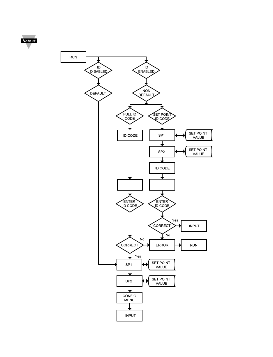
any configuration change other than Setpoints & Alarms.
Figure 3.1 Flow Chart for ID and Setpoints

16
3.2.1 ID Number
SEE ID MENU SELECTION IN CONFIGURATION SECTION FOR
ENABLE/DISABLE OR CHANGE ID CODE.
If ID Code is Disabled or set as Default (0000) the menu will skip ID step
to Setpoint Menu.
If ID Code is set to Full Security Level and user attempts to enter the
Main Menu, they will be prompted for an ID Code.
If ID Code is set to Setpoint/ID Security Level and user attempts to enter
the Configuration Menu, they will be prompted for an ID Code.
ENTERING YOUR NON-DEFAULT FULL SECURITY ID NUMBER.
Press a 1) Display shows ID.
Press d 2) Display advances to
____
.
Press b & c 3) Press bto increase digit 0-9. Press cto activate next digit
(flashing). Continue to use band c to enter your 4-digit ID
code.
Press d 4) If the correct ID code is entered, the menu will advance to the
Setpoint 1 Menu, otherwise an error message
ERRo
will be
displayed and the instrument will return to the Run Mode.
To change ID Code, see ID Menu in the Configuration section.
ENTERING YOUR NON-DEFAULT SETPOINT/ID SECURITY ID NUMBER.
Press a 5) Display shows
SP1
Setpoint 1 Menu.
Press a 6) Display shows
SP2
Setpoint 2 Menu.
Press a 7) Display shows IDID Code Menu.
Press d 8) Display advances to
____
.
Press b & c 9) Use b and c to change your ID Code.
Press d 10) If correct ID Code is entered, the display will advance to the
INPT
Input Menu, otherwise the error message
ERRo
will be
displayed and the controller will return to the Run Mode.
To prevent unauthorized tampering with the setup parameters, the
instrument provides protection by requiring the user to enter the ID Code
before allowing access to subsequent menus. If the ID Code entered
does not match the ID Code stored, the controller responds with an error
message and access to subsequent menus will be denied.
Use numbers that are easy for you to remember. If the ID Code is
forgotten or lost, call customer service with your serial number to access
and reset the default to
0000
.

17
3.2.2 Set Points
SETPOINT 1:
Press a 1) Press a, if necessary until
SP1
prompt appears.
Press d 2) Display shows previous value of “Setpoint 1”.
Press b & c 3) Press b and c to increase or decrease Setpoint 1
respectively.
Holding b & c buttons down for approximately 3 seconds will speed up the
rate at which the Setpoint value increments or decrements.
Press b & c 4) Continue to use b and c to enter your 4-digit Setpoint 1 value.
Press d 5) Display shows
STRD
stored message momentarily and then
advances to
SP2
only, if a change was made, otherwise press
a to advance to
SP2
Setpoint 2 Menu.
SETPOINT 2:
Press d 6) Display shows previous value of “Setpoint 2”.
Press b & c 7) Press b and c to increase or decrease Setpoint 2
respectively.
Holding b & c buttons down for approximately 3 seconds will speed up
the rate at which the setpoint value increments or decrements.
Press d 8) Display shows
STRD
stored message momentarily and then
advances to
CNFG
only, if a change was made, otherwise press
a to advance to
CNFG
Configuration Menu.
18
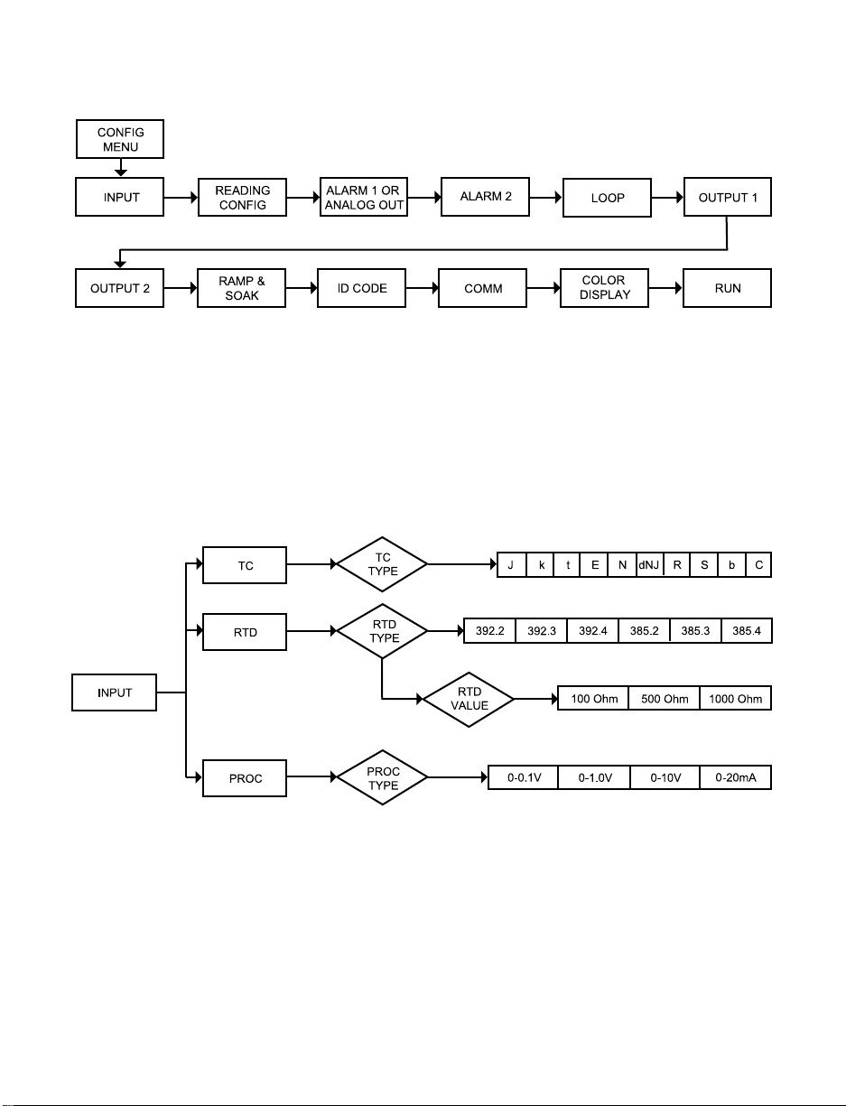
3.2.3 Configuration Menu
Figure 3.2 Flow Chart for Configuration Menu
Enter Configuration Menu:
Press a 1) Press a, if necessary, until
CNFG
prompt appear.
Press d 2) Display advances to
INPT
Input Menu.
Press a 3) Pressing and releasing a to scroll through all available
menus of Configuration section.
3.2.4 Input Type Menu
Figure 3.3 Flow Chart for Input Type Menu
 Loading...