

Page 1
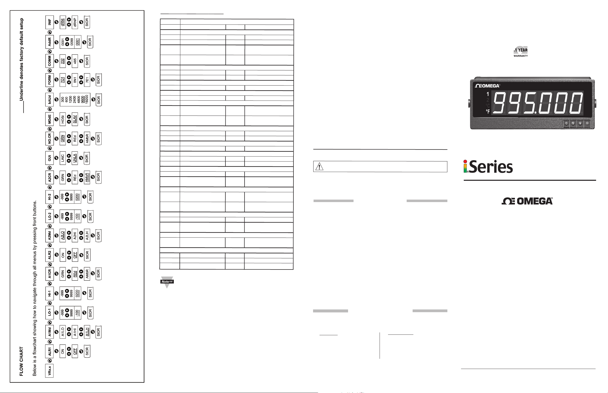
FLOW CHART _____Underline denotes factory default setup
Below is a flowchart showing how to navigate through all menus by pressing front buttons.
DISPLA
ddddddd
ALR1 Alarm 1 Status
OFF Alarm 1 set Off ON Alarm 1 set On
a
A1Md Alarm 1 Mode
A1LO Alarm 1 Low A1HI Alarm 1 High
b c
d
A1LH Alarm 1 Low/High
LO-1 Alarm 1 Low -999.. Alarm 1 Low Value
HI-1 Alarm 1 High -999.. Alarm 1 High Value
a a
d
A1CR Display color when Alarm 1 triggered
GRN Green Color REd Red Color
AMbR Amber Color
ALR2 Alarm 2 Status
OFF Alarm 2 set Off ON Alarm 2 set On
A2Md Alarm 2 Mode
d
A2LO Alarm 2 Low A2HI Alarm 2 High
A2LH Alarm 2 Low/High
LO-2 Alarm 2 Low -999.. Alarm 2 Low Value
HI-2 Alarm 2 High -999.. Alarm 2 High Value
aa a a
cb d c db d
d
A2CR Display color when Alarm 2 triggered
GRN Green Color REd Red Color
AMbR Amber Color
Y
ABBREVIA
TIONS
..9999
..9999
..9999
..9999
SPECIFICATION
Temperature Stability:
50 ppm/°C
Display:
6-digit, 7-segment LED, 57.2mm (2.25”)
with red, green and amber programmable
colors.
Alarm:
Alarm 1 & 2 programmable,
Latch/Unlatch, High, Low, High/Low
Standards Compliance:
IEEE 802.3 10Base-T
Supported Protocols:
TCP/IP, ARP, HTTPGET
SERIAL INTERFACE
Communication Standard:
RS485, RS422
Transfer speed (Baud rate):
300, 600, 1200, 2400, 4800, 9600,
19200 bps
Data Format:
7O1-7 bit, Odd,1stop bit, 7E1- 7 bit,
even, 1 stop bit
8N1 – 8 bit, No parity, 1 stop bit
Multi-point Address (RS485):
0 to 199
Flow Control:
No Flow control
Screw terminals for RS-485/422
interface
NETWORK INTERFACE
10Base-T port (RJ45 connector)
Socket Port number:
1000
HTTP Port number:
80
Power Supply:
100-240 Vac
Operating Temperature:
0 to 40°C
Storage Temperature:
-20 to 60°C
Relative Humidity:
0 to 85%
Protection:
NEMA-4x (IP65)
Dimensions:
394 Lx 137Wx73Dmm
(15.50" x 5.375" x 2.875")
Panel Cutout:
374 L x 116.8 W mm
(14.75” L x 4.60” W)
Weight:
2,040 g (4.5 lbs)
Approvals:
per
EN61010-1
±
EN50081-1,
10%, 50/60 Hz, 22.5 W
EN50082-2,
OPERATION MANUAL
RoHS 2 Compliant
OUt Alarm Latched/Unlatched selection
LAtC Latched UNLA Unlatched
cb
d
d
a
cb
cb
d
d
a
cb
NO.CR Display Color in Normal condition
GRN Green Color REd Red Color
AMbR Amber Color
MOdE Data Flow Mode
HOSt Host Mode SLAV Slave Mode
bAUd Baud Rate 300.. Baud Rate Value
..19200
FORM Data Format
7O1 7 Bit, Odd, 7E1 7 Bit, Even,
1 Stop Bit 1 Stop Bit
a
cbcb
d dd
d d
a
cb
cb
d
8N1 8 Bit, No parity,
1 Stop Bit
COMM Communication Standard
232 RS-232 Standard 485 RS-485 Standard
AddR Device Address 0000.. Address Value
..0099
INtF Interface Device
dRNt DRN with dRNP DRN with
a
cb
d
d
Miscellaneous:
PEAk Peak Value VALL Valley Value
Temperature Input Process Input
PROC Process Value RUN Run Mode
a
cb
cb
d
d
a
cb
a
d dd
d d
OVLd Input Overload StOR Stored Message
1. In Slave Mode the Big Display will wait for
commands and data from the Serial Bus.
2. In Host Mode the Big Display will send data
automatically and continuously into the Serial Bus.
3. When used in RS-485 Mode, the device must be
accessed with an appropriate Address Value.
4. Latched Mode:
To reset already latched alarm select any
items
and then press “up” or “down” button.
Alarm remains latched until
menu
reset.
a
cb
cb
d
a
cb cbcbcbcbcb
d
d
a
WARNING: These products are not designed for use in, and should not be used for, patientconnected applications.
This device is marked with the international caution symbol.
Setup Guide before installing or commissioning this device, as the guide contains important
information relating to safety and EMC.
It
is
the
policy
of
OMEG
A
to
comply
with
all
worldwide
OEMGAis
constantly
pursuing
certification
of
OMEGAwill
The
accepts
OMEGA ENGINEERING, INC. warrants this unit to be free of defects in materials and workmanship
for a period of 13 months from date of purchase. OMEGA’s Warranty adds an additional one (1)
month grace period to the normal one (1) year product warranty to cover handling and shipping
time. This ensures that OMEGA’s customers receive maximum coverage on each product.
If the unit malfunctions, it must be returned to the factory for evaluation. OMEGA’s Customer
Service Department will issue an Authorized Return (AR) number immediately upon phone or
written request. Upon examination by OMEGA, if the unit is found to be defective, it will be repaired
or replaced at no charge. OMEGA’s WARRANTY does not apply to defects resulting from any action
of the purchaser, including but not limited to mishandling, improper interfacing, operation outside
of design limits, improper repair, or unauthorized modification. This WARRANTY is VOID if the
unit shows evidence of having been tampered with or shows evidence of having been damaged
as a result of excessive corrosion; or current, heat, moisture or vibration; improper specification;
misapplication; misuse or other operating conditions outside of OMEGA’s control. Components in
which wear is not warranted, include but are not limited to contact points, fuses, and triacs.
OMEGA is pleased to offer suggestions on the use of its various products. However,
OMEGA neither assumes responsibility for any omissions or errors nor assumes
liability for any damages that result from the use of its products in accordance with
information provided by OMEGA, either verbal or written. OMEGA warrants only that
the parts manufactured by the company will be as specified and free of defects. OMEGA
MAKES NO OTHER WARRANTIES OR REPRESENTATIONS OF ANY KIND WHATSOEVER,
EXPRESSED OR IMPLIED, EXCEPT THAT OF TITLE, AND ALL IMPLIED WARRANTIES
INCLUDING ANY WARRANTY OF MERCHANTABILITY AND FITNESS FOR A PARTICULAR
PURPOSE ARE HEREBY DISCLAIMED. LIMITATION OF LIABILITY: The remedies of
purchaser set forth herein are exclusive, and the total liability of OMEGA with respect
to this order, whether based on contract, warranty, negligence, indemnification, strict
liability or otherwise, shall not exceed the purchase price of the component upon which
liability is based. In no event shall OMEGA be liable for consequential, incidental or
special damages.
CONDITIONS: Equipment sold by OMEGA is not intended to be used, nor shall it be used: (1) as
a “Basic Component” under 10 CFR 21 (NRC), used in or with any nuclear installation or activity;
or (2) in medical applications or used on humans. Should any Product(s) be used in or with any
nuclear installation or activity, medical application, used on humans, or misused in any way,
OMEGA assumes no responsibility as set forth in our basic WARRANTY/ DISCLAIMER language,
and, additionally, purchaser will indemnify OMEGA and hold OMEGA harmless from any liability or
damage whatsoever arising out of the use of the Product(s) in such a manner.
Direct all warranty and repair requests/inquiries to the OMEGA Customer Service Department.
BEFORE RETURNING ANY PRODUCT(S) TO OMEGA, PURCHASER MUST OBTAIN AN AUTHORIZED
RETURN (AR) NUMBER FROM OMEGA’S CUSTOMER SERVICE DEPARTMENT (IN ORDER TO
AVOID PROCESSING DELAYS). The assigned AR number should then be marked on the outside
of th e retu rn pac kage a nd on any co rresp onden ce. The purchaser is responsible for shipping charges,
freight, insurance and proper packaging to prevent breakage in transit.
FOR WARRANTY RETURNS, please have
the following information available BEFORE
contacting OMEGA:
1.
2.
3. Repair instructions and/or specific problems
OMEGA’s policy is to make running changes, not model changes, whenever an improvement is possible. This affords our customers the latest in technology and engineering.
OMEGA is a registered trademark of OMEGA ENGINEERING, INC.
© Copyright 2017 OMEGA ENGINEERING, INC. All rights reserved. This document may not be copied, photocopied, reproduced, translated, or reduced to any electronic medium or machine-readable
form, in whole or in part, without the prior written consent of OMEGA ENGINEERING, INC.
add
th
e
mark
to
information
no
liability
contained
every
in
this
errors
it
for
any
WARRANTY/ DISCLAIMER
OMEGA ENGINEERING, INC. warrants this unit to be free of defects in materials and workmanship for a period of
one (1) year from the date of purchase. In addition to OMEGA’s standard warranty period, OMEGA Engineering will
extend the warranty period for four (4) additional years if the warranty card enclosed with each instrument is
returned to OMEGA.
If the unit malfunctions, it must be returned to the factory for evaluation. OMEGA’s Customer Service Department will
issue an Authorized Return (AR) number immediately upon phone or written request. Upon examination by OMEGA,
if the unit is found to be defective, it will be repaired or replaced at no charge. OMEGA’s WARRANTY does not apply
to defects resulting from any action of the purchaser, including but not limited to mishandling, improper interfacing,
operation outside of design limits, improper repair, or unauthorized modification. This WARRANTY is VOID if the unit
shows evidence of having been tampered with or shows evidence of having been damaged as a result of excessive
corrosion; or current, heat, moisture or vibration; improper specification; misapplication; misuse or other operating
conditions outside of OMEGA’s control. Components which wear are not warranted, including but not limited to
contact
points, fuses, and triacs.
OMEGA is pleased to offer suggestions on the use of its various products. However, OMEGA neither
assumes responsibility for any omissions or errors nor assumes liability for any damages that result from
the use of its products in accordance with information provided by OMEGA, either verbal or written. OMEGA
warrants only that the parts manufactured by it will be as specified and free of defects. OMEGA MAKES NO
OTHER WARRANTIES OR REPRESENTATIONS OF ANY KIND WHATSOEVER, EXPRESS OR IMPLIED,
EXCEPT THAT OF TITLE, AND ALL IMPLIED WARRANTIES INCLUDING ANY WARRANTY OF
MERCHANTABILITY AND FITNESS FOR A PARTICULAR PURPOSE ARE HEREBY DISCLAIMED. LIMITATION
OF LIABILITY: The remedies of purchaser set forth herein are exclusive, and the total liability of OMEGA with
respect to this order, whether based on contract, warranty, negligence, indemnification, strict liability or
otherwise, shall not exceed the purchase price of the component upon which liability is based. In no event
shall OMEGA be liable for consequential, incidental or special damages.
CONDITIONS: Equipment sold by OMEGA is not intended to be used, nor shall it be used: (1) as a “Basic
Component” under 10 CFR 21 (NRC), used in or with
or used on humans. Should any Product(s) be used in or with any nuclear installation or activity, medical application,
used on humans, or misused in any way, OMEGA assumes no responsibility as set forth in our basic
WARRANTY/DISCLAIMER language, and, additionally, purchaser will indemnify OMEGA and hold OMEGA harmless
from any liability or damage whatsoever arising out of the use of the Product(s) in such a manner.
Direct all warranty and repair requests/inquiries to the OMEGA Customer Service Department. BEFORE
RETURNING ANY PRODUCT(S) TO OMEGA, PURCHASER MUST OBTAIN AN AUTHORIZED RETURN (AR)
NUMBER FROM OMEGA’S CUSTOMER SERVICE DEPARTMENT (IN ORDER TO AVOID P ROCESSING
DELAYS). The assigned AR number should then be marked on the outside of the return package and on any
correspondence.
The purchaser is responsible for shipping charges, freight, insurance and proper packaging to prevent breakage in
transit.
FOR W
ARRANTY
following information available BEFORE
contacting OMEGA:
1. Purchase Order number under which the product
was PURCHASED,
2. Model and serial number of the product under
warranty, and
3. Repair instructions and/or specific problems
relative to the product.
Purchase Order number under which the
OMEGA’s policy is to make running changes, not model changes, whenever an improvement is possible. This affords
product was PURCHASED,
our customers the latest in technology and engineering.
Model and serial number of the product under
© Copyright 2005 OMEGA ENGINEERING, INC. All rights reserved. This document may not be copied, photocopied,
warranty, and
reproduced, translated, or reduced to any electronic medium or machine-readable form, in whole or in part, without
the prior written consent of OMEGA ENGINEERING, INC.
relative to the product.
PATENT AND TRADEMARK NOTICE: This product is covered by one or more of the following patents: U.S. Pat.
No. Des. 336,895; 5,274,577; 6,243,021/ CANADA2052599; 2052600/ ITALY 1249456; 1250938/ GERMANYDE 41
34398 C2/ SPAIN 2039150; 2048066/ UK Patent No. GB2 249 837; GB2 248 954/ FRANCE BREVETNO. 91 12756.
Other U.S. and International Patents pending or applied for.
RETURN REQUESTS/ INQUIRIES
RETURNS, please have the
appropriate
document
is
contains,
and
WARRANTY/DISCLAIMER
RETURN REQUESTS/INQUIRIES
safety
its
products
device
upon
believed
to
reserves
the
any nuclear installation or activity; or (2) in medical applications
FOR NON-W
current repair charges. Have the following information
available BEFORE contacting OMEGA:
1. Purchase Order number to cover the COST of the
repair,
2. Model and serial number of product, and
FOR NON-WARRANTY REPAIRS,
3. Repair instructions and/or specific problems
OMEGA for current repair charges. Have
relative to the product.
the following information available BEFORE
contacting OMEGA:
1. Purchase Order number to cover the COST
of the repair,
2. Model and serial number of the product, and
3. Repair instructions and/or specific problems
relative to the product.
It is important to read the
and
EMC/EMI
to
the
European
certification
be
right
ARRANTY
.
correct,
but
to
alter
REPAIRS, consult OMEGA for
regulations
New
Approach
OMEG
A
specifications
that
Directives
Engineering
without
consult
M4193/0605
M3837/2017
appl
,
Inc
notice.
iLD26-EI
Big Display with
y
.
.
.
omega.com [email protected]
Servicing North America:
U.S.A. Omega Engineering, Inc.
Headquarters: Toll-Free: 1-800-826-6342 (USA & Canada only)
The information contained in this document is believed to be correct, but OMEGA accepts no
liability for any errors it contains, and reserves the right to alter specifications without notice.
Customer Service: 1-800-622-2378 (USA & Canada only)
Engineering Service: 1-800-872-9436 (USA & Canada only)
Tel: (203) 359-1660 Fax: (203) 359-7700
e-mail: [email protected]
For Other Locations Visit omega.com/worldwide
Embedded Ethernet
Page 2
CONFIGURATION
Button Functions in Configuration Mode
• To enter the Menu, the user must first press
a
button.
• Use this button to advance/navigate to the next menu
item. The user can navigate through all the top level
menus by pressing
a
.
• While a parameter is being modified, press
a
to
escape without saving the parameter.
• Press the up
b
button to scroll through submenu
selections. When a numerical value is displayed press
this key to increase value of a parameter that is
currently being modified.
• In the Run Mode pressing
b
causes the display
to flash the PEAK value several times before returning
to the Run Mode.
• In the top menu press
b
causes the display to return to
the Run Mode.
• Press the down
c
button to scroll through submenu
selections. When a numerical value is displayed press
this key to decrease value of a parameter that is
currently being modified.
• In the Run Mode press c causes the display to flash
the Valley value several times before returning to the
Run Mode.
• In the top menu press c causes the display to return to
the Run Mode.
• Press this button to access the submenus from a T
op
Level Menu item.
• Press this button to store a submenu selection or after
entering a value – the display will flash a
message to confirm your selection.
x, w, z, and some punctuations are non-printable characters.
(ENTER)
(DOWN)
(UP)
a
(MENU)
iLD26-EI Big Display with Embedded Ethernet
DESCRIPTION:
The iLD26-EI is a 6-digit master/slave display providing remote
readout from instruments such as programmable controllers, digital
panel meters and other instruments with serial or Ethernet output.
Communication interfaces supported in the iLD26-EI are Ethernet
and RS-485 standards. RS-485 is programmable through front
panel buttons.
The iLD26-EI features a large three color programmable display
with the capabitity to change color every time an Alarm is triggered.
The latest complete Operational Manuals as well as free Software
and ActiveX Controls are available at: www.omega.com or
on the CD-ROM enclosed with your shipment.
SAFETY:
• The instrument is a panel mount device protected in
accordance with Class III of IEC 1010.
EMC:
• Whenever EMC is an issue, always use shielded cables.
• Never run signal and power wires in the same conduit.
signal wire connections with twisted-pair cables.
• Use
• Install Ferrite Bead(s) on signal wire close to the instrument if
EMC problems persist.
MOUNTING
Mounting Big Display on Bail:
1. Use the Big Display template to mark the location of
mounting screws on the flat surface.
Be sure to leave enough room around the bail (as noted on the
2.
template drawing) to allow for removal and rotation of the display.
3. The display can be rotated for the best viewing angle.
Disassembly Instruction:
Warning: Disconnect all ac power from the unit before
proceeding.
Remove all wiring connections from the rear of the instrument, by
1.
unscrewing the power and input connectors.
Remove six screws at the back of the display and back cover.
2.
3. Remove the
Big Display
4. To remove the
Big Display
from the panel.
from the bail, unscrew the two
knobs at each end of the mounting brackets.
WIRING
iring Ethernet Interface
1. W
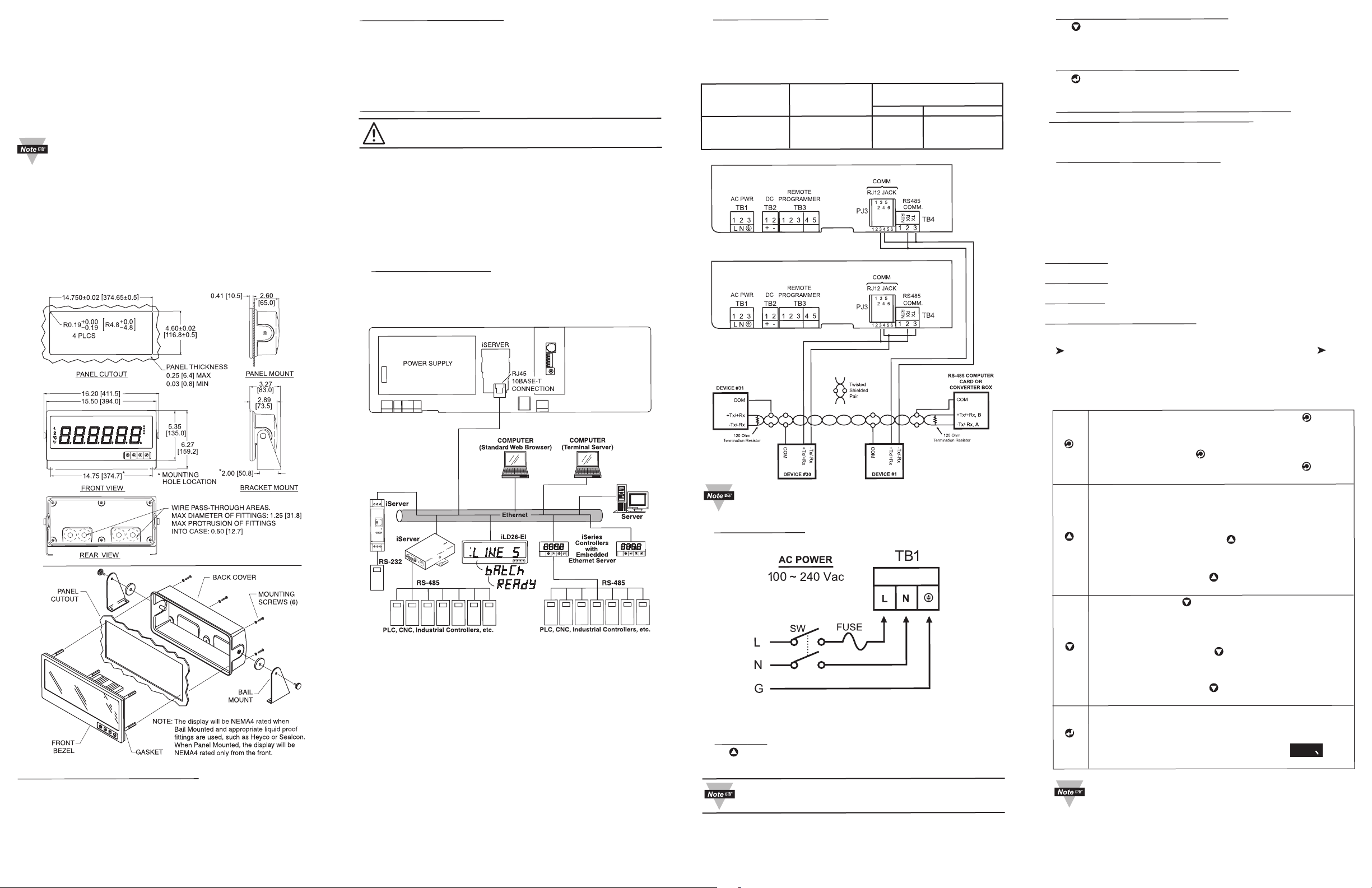
The embedded Ethernet Server is designed to connect industrial
devices with serial interfaces to the Ethernet network using TCP/IP
Protocol.
iring RS-485 Interface.
2. W
The RS-485 standard (multipoint) allows a computer, one or more
devices and Big Displays (up to 32) to be connected using a twowire connection (half-duplex) plus a common wire to connect to the
shield of the cable. It is recommended to use shielded cable with
one twisted pair for EMI noise protection.
Computer Card Device with Remote Display
or Converter Box RS-485 Pin
Pin Function Function RJ-12 Screw Terminal
A, -Tx/-Rx -Tx/-Rx 4 3
B, +Tx/+Rx +Tx/+Rx 3 2
1MOCMOC
alue (Display on Host Mode)
alley V
2. V
Press
to request “Valley” value.
c
RS-485 Mode, will send:
*01X03 (Interface DRNT), or *01X04 (Interface DRNP)
3. Process V
Press
RS-485 Mode, will send: *01X01
rite alphanumeric characters to the Big Display
4. W
alue (Display on Host Mode)
to request “Process” Value.
d
from the computer (Display in Slave Mode)
Multiple Big Display: (RS485) write *, device address
(2 digit), CR, 6 characters, then CR
5. Display Color Setup (Alarm Setup)
This menu allows the user to select the color of the display in
normal conditions and when alarm is triggered. If user wants the
Display to change color every time when both Alarm 1 and Alarm 2
are triggered, the Alarm values should be set in such a way that
Alarm 1 is always on the top of Alarm 2 value, otherwise value of
the Alarm 1 will overwrite value of Alarm 2 and Display color would
not change when Alarm 2 is triggered.
Example 1:
“ON”, Alarm Mode High “A1HI”, Alarm High
Alarm 1 setup
:
Value “HI-1”=400, Alarm Color “A1CR”=Amber
“ON”, Alarm Mode High “A2HI”, Alarm High
Alarm 2 setup
:
Value “HI-2”=200, Alarm Color “A2CR”=Red
“NO.CR”=Green
Normal Color
:
COL
ON
TX
RX
Mounting Big Display Through Panel:
Using the panel cutout diagram shown above, cut an opening in
1.
the panel.
Remove six screws at the back of Big Display to remove back cover.
2.
Insert the unit into the opening from the front of the panel, so the
3.
gasket seals between the bezel and the front of the panel.
4. Align back cover to
Big Display
and reinstall screws.
TX RX RTN
COMMUNICATIONS
DC POWER IN
+ - N/C
Display colors change sequences
:
GREEN I RED I AMBER
-------------------------
--
•
--------------------------------
•
----------------
•
0 HI-2 = 200 HI-1 = 400
Connections to the computer are optional.
ETHERNET
RESET
RX TX ON COL
3. Power Connection.
Connect the main power connections as shown in the figure below.
POWER
OPERATIONS
(Display in Host Mode)
1. Peak V
Press
alue
to request “Peak” value:
b
RS-485 Mode, will send:
st0P
*01X02 (Interface DRNT), or *01X03 (Interface DRNP)
In the examples for RS-485 it is assumed that the
device address is 01.
 Loading...