

Page 1
Step 30. Select the Deadband Value Submenu
Press d. The display will show
020.0
, otherwise
press bor c.Press dto store and advance to next menu
item.
Step 31. Enter the Alarm 2 Menu
The display will show
ALR2
the top menu for Alarm 2.
Repeat steps from 29 and 30 to set for Alarm 2 the same
conditions as for Alarm 1.
Step 32. Configuration of Display Color Selection
Press auntil the
COLR
Display Color Selection Menu
appears on the Display. Configure
COLR
as
N.CLR/GRN
(green),
1.CLR/ RED
(red),
2.CLR/AMBR
(amber). Please
refer to the operator’s manual if needed.
For color change on Setpoints refer to Owners
Manual Section 2.
Step 33. Run a Test
Press a until reset the controller and return to RUN Mode to
display
075.0
(Ambient Temperature). Now you are ready
to observe temperature as it rises 10°F higher than
displayed. Touch the tip of the Thermocouple to raise the
temperature above the Alarm 2 High value
082.0
, and AL2
will turn on, and Display Color will change from Green to
Amber. Continue touching the tip to raise the temperature
above the Alarm 1 High value
087.0
and Display Color will
change from Amber to Red. Annunciator “1” is turning on
and off displaying output 1.
Step 11. Enter to the Thermocouple Type Input Submenu
Press dto display flashing, previously selected
Thermocouple type.
Step 12. Scroll through available selection of TC types
Press bto sequence thru flashing Thermocouple types,
(select k -for type "K" CHROMEGA®/ALOMEGA®)
J K T E N DIN J R S B C - TC types
J k t E N dN J R S b C - Display
Step 13. Store TC type
After you have selected the Thermocouple type press dto
store your selection, the instrument automatically advances
to the next menu item.
Step 14. Enter to Reading Configuration Menu
The display shows
RDG
Reading Configuration, which is the
top menu for 4 submenus: Decimal Point, Degree Units,
Filter Constant and Input/Reading Submenus.
Step 15. Enter to Decimal Point Submenu
Press dto show
DEC
Decimal Point.
Step 16. Display the Decimal Point position
Press dagain to display the flashing Decimal Point position.
Step 17. Select the Decimal Point position
Press bto select
FFF.F
Decimal Point position.
Step 18. Store selected Decimal Point position
By pressing dmomentarily the Decimal Point position will
be stored and the instrument will go to the next menu item.
Step 19. Enter to Temperature Unit Submenu
Display shows
TEMP
Temperature Unit.
Step 20. Display available Temperature Units
Press dto display the flashing Degree °For °C.
Step 21. Scroll through Temperature Units selection
Press bto select °FDegree.
Step 22. Store the Temperature Unit
Press dto display momentarily that the Degree Unit has
been stored and the instrument will go automatically to the
next menu item.
Step 23. Enter the Filter Constant Submenu
Display shows
FLTR
Filter Constant Submenu.
Step 24. Display the Filter Constant Value Submenu
Press dto display the flashing, previously selected Filter
Constant.
Step 25. Scroll through available Filter Constants
Press bto sequence thru Filter Constants
0001, 0002
,
0004, 0008, 0016, 0032, 0064
and
0128
.
Step 26. Store the Filter Constant
Press dmomentarily to store
0004
Filter Constant and the
instrument will automatically go to the next menu item.
Step 27. Enter Alarm 1 Menu
Press auntil the
ALR1
Alarm 1 Menu appears on the
Display. In the following steps we are going to Disable
Latch, Active Above, Deadband 020.0, and above Setpoint 1
Value will activate Alarm 1.
Step 28. Select Latch Type Submenu
Press dto display flashing
DSBL/ ENBL
. If flashing
DSBL
is displayed, press a, if
ENBL
is displayed, press buntil
DSBL
is displayed, then press dto store and go to the next
menu item.
Step 29. Select the Above Type of Active Submenu
Press d. If flashing
ABoV
Above is displayed, press a,
otherwise press buntil
ABoV
is displayed. Press dto store
and advance to next menu item.
MQS3716-SM/0305
iLD24 Big Display
Universal Temperature
& Process
Simplified Menu (-SM)
SPECIFICATION
Accuracy:
0.5°C temp;
+
0.03% rdg. process typical
Resolution:
°
/0.1
°; 10 µV
1
Temperature Stability:
0.04°C/°C RTD;
0.05°C/°C TC @ 25°C (77°F);
50 ppm/°C process
Display:
4-digit, 7-segment LED, 57.2 mm (2.25")
with red, green, and amber programmable
colors for process variable, set point and
temperature units.
Input Types:
Thermocouple, RTD, Analog Voltage
and Current
TC: (ITS 90)
J, K, T, E, R, S, B, C, N, L
RTD: (ITS 68)
100/500/1000 ohm Pt sensor
2-, 3-, or 4-wire; 0.00385 or 0.00392 curve
Voltage:
0 to 100 mV, 0 to 1 V, 0 to 10 Vdc
Current:
0 to 20 mA (4 to 20 mA)
process
†
Output 1
Output 2†:
Options: Communication
Power:
Dimensions:
Panel Cutout:
Weight:
Approvals:
:
Relay 250 Vac @ 3 A Resistive Load,
SSR, Pulse, Analog Voltage and Current
Relay 250 Vac @ 3 A Resistive Load,
SSR, Pulse
†
Only for Alarms
RS-232 / RS-485 or
Excitation:
100-240 Vac ±10%,
289 L x 137 W x 73 D mm
(11.75” L x 5.375” W x 2.875” D)
279.4 L x 116.8 W mm
(11.00” L x 4.60” W)
1,360 g (3 lbs)
per EN 61010-1:2001
24 Vdc
50-60 Hz, 22.5 W
WARRANTY/DISCLAIMER
OMEGA ENGINEERING, INC. warrants this unit to be free of defects
in materials and workmanship for a period of 61 months from
date of purchase. OMEGA’s WARRANTY adds an additional one (1)
month grace period to the normal five (5) year product warranty
to cover handling and shipping time. This ensures that OMEGA’s
customers receive maximum coverage on each product.
If the unit malfunctions, it must be returned to the factory for evaluation. OMEGA’s Customer Service Department will issue an Authorized
Return (AR) number immediately upon phone or written request.
Upon examination by OMEGA, if the unit is found to be defective, it
will be repaired or replaced at no charge. OMEGA’s WARRANTY does
not apply to defects resulting from any action of the purchaser, including but not limited to mishandling, improper interfacing, operation
outside of design limits, improper repair, or unauthorized modification. This WARRANTY is VOID if the unit shows evidence of having
been tampered with or shows evidence of having been damaged as a
result of excessive corrosion; or current, heat, moisture or vibration;
improper specification; misapplication; misuse or other operating
conditions outside of OMEGA’s control. Components in which wear
is not warranted, include but are not limited to contact points, fuses,
and triacs.
OMEGA is pleased to offer suggestions on the use of its various products. However, OMEGA neither assumes responsibility for any omissions or errors nor assumes liability for any
damages that result from the use if its products in accordance
with information provided by OMEGA, either verbal or written. OMEGA warrants only that the parts manufactured by
the company will be as specified and free of defects. OMEGA
MAKES NO OTHER WARRANTIES OR REPRESENTATIONS OF
ANY KIND WHATSOEVER, EXPRESSED OR IMPLIED, EXCEPT
THAT OF TITLE, AND ALL IMPLIED WARRANTIES INCLUDING
ANY WARRANTY OF MERCHANTABILITY AND FITNESS
FOR A PARTICULAR PURPOSE ARE HEREBY DISCLAIMED.
LIMITATION OF LIABILITY: The remedies of purchaser set
forth herein are exclusive, and the total liability of OMEGA
with respect to this order, whether based on contract, warranty, negligence, indemnification, strict liability or otherwise,
shall not exceed the purchase price of the component upon
which liability is based. In no event shall OMEGA be liable for
consequential, incidental or special damages.
CONDITIONS: Equipment sold by OMEGA is not intended to be used,
nor shall it be used: (1) as a “Basic Component” under 10 CFR 21 (NRC),
used in or with any nuclear installation or activity; or (2) in medical applications or used on humans. Should any Product(s) be used in or with
any nuclear installation or activity, medical application, used on humans,
or misused in any way, OMEGA assumes no responsibility as set forth
in our basic WARRANTY/DISCLAIMER language, and, additionally,
purchaser will indemnify OMEGA and hold OMEGA harmless from any
liability or damage whatsoever arising out of the use of the Product(s)
in such a manner.
RETURN REQUESTS/INQUIRIES
Direct all warranty and repair requests/inquiries to the OMEGA
Customer Service Department. BEFORE RETURNING ANY
PRODUCT(S) TO OMEGA, PURCHASER MUST OBTAIN AN
AUTHORIZED RETURN (AR) NUMBER FROM OMEGA’S CUSTOMER
SERVICE DEPARTMENT (IN ORDER TO AVOID PROCESSING
DELAYS). The assigned AR number should then be marked on the
outside of the return package and on any correspondence.
FOR WARRANTY RETURNS,
please have the following
information available BEFORE
contacting OMEGA:
1. Purchase Order number
under which the product
was PURCHASED,
2.3. Model and serial number of the
product under warranty, and
Repair instructions and/or
specific problems relative
to the product.
OMEGA’s policy is to make running changes, not model changes,
whenever an improvement is possible. This affords our customers
the latest in technology and engineering.
OMEGA is a trademark of OMEGA ENGINEERING, INC.
© Copyright 2018 OMEGA ENGINEERING, INC. All rights reserved.
This document may not be copied, photocopied, reproduced,
translated, or reduced to any electronic medium or machine-readable
form, in whole or in part, without the prior written consent of OMEGA
ENGINEERING, INC.
FOR NON-WARRANTY REPAIRS,
consult OMEGA for current repair
charges. Have the following
information available BEFORE
contacting OMEGA:
1. Purchase Order number to cover
the COST of the repair or
calibration,
2.3.Model and serial number of the
product, and
Repair instructions and/or specific
problems relative to the product.
TM
omega.com [email protected]
U.S.A. Omega Engineering, Inc.
Headquarters: Toll-Free: 1-800-826-6342 (USA & Canada only)
The information contained in this document is believed to be correct, but
OMEGA accepts no liability for any errors it contains, and reserves the right to
alter specifications without notice.
Servicing North America:
Customer Service: 1-800-622-2378 (USA & Canada only)
Engineering Service: 1-800-872-9436 (USA & Canada only)
Tel: (203) 359-1660 Fax: (203) 359-7700
e-mail: [email protected]
For Other Locations Visit omega.com/worldwide
Page 2
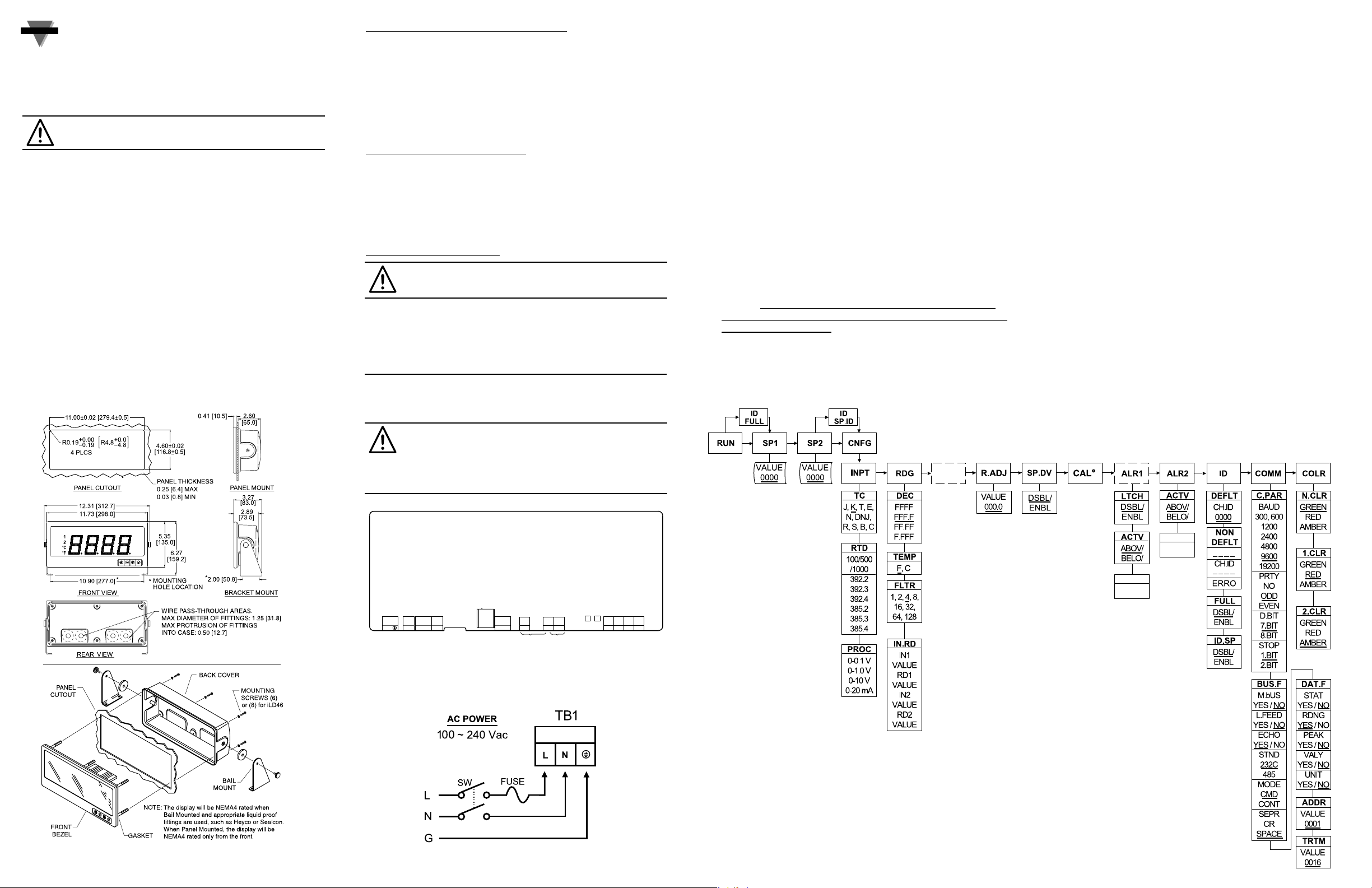
FLOW CHART
CONFIGURATION
MENU Mode:
Flashing display in MENU Mode means you can make your
selection by pressing bbutton. If the flashing display is not
a four digit value, pressing cbutton will always direct the
instrument one step backward of the top menu item. The
second push on the cbutton will reset the instrument
except after the setpoint and the alarms, that will go to the
RUN Mode without resetting the instrument. The abutton
will always sequence the instrument thru the menu items.
The dbutton has two functions:
1. To save a selected flashing display
2. To direct the instrument to the next submenu level
RUN Mode:
b
causes the display to flash the PEAK with the
corresponding value. Press again to go back to RUN
Mode.
c
causes the display to flash VALLEY with the
corresponding value. Press again to go back to RUN
Mode.
d
causes flashing PEAK or VALLEY to reset corresponding
values. Pressing
d twice will cause the display to flash
STBY and put the instrument into standby, which disables
all outputs and alarms. Press done more time to go
back to RUN Mode.
OPERATION - (For Thermocouple Input)
Step 1. Apply Power to the Instrument
When your device is first powered up it will display the
ambient temperature (assume 75°F).
Step 2. Enter Setpoint 1 Menu
Press aone time from run mode to get to
SP1
Setpoint 1.
Step 3. Enter the Setpoint 1 Value Submenu
Press d. Display shows the previous selection of Setpoint 1.
Step 4. Change the Setpoint 1 Value
Press bor cuntil desired value is displayed.
Step 5. Store the Setpoint 1 Value
Set the Setpoint 1 to 10 degree higher than Process value
(SP1 = 85) and press dto store, display flashes
STRD
message and advances to
SP2
Setpoint 2 Menu.
Step 6. Store the Setpoint 2 Value
Repeat steps 3 and 4. Set the Setpoint 2 to 5 degree higher
than Process value (SP2 = 80) and press dto store,
display flashes
STRD
message and advances to
CNFG
Configuration Menu.
Step 7. Enter the Input Type Menu
Press dto enter
INPT
Input Type Menu.
Step 8. Enter to the submenu items of Input Menu
Press dto display Input: Process, RTD or Thermocouple.
If flashing
T.C
is displayed press a and proceed to Step 11.
Step 9. Scroll through available selection of Input Menu
Press buntil a flashing
T.C
for Thermocouple is displayed.
Step 10. Enter to the Thermocouple Input Submenu
Press dto store Thermocouple Input. The display will stop
flashing and show the top menu for Thermocouple types. If
you press aunit will step to next menu item (Skip to Step 14).
_____ Underline denotes factory default setup
his Quick Start Reference provides information
on setting up your instrument for basic operation.
The latest complete Communication and Operational
Manual as well as free Software and ActiveX Controls
are available at www.omega.com or on the CD-ROM
enclosed with your shipment.
SAFETY CONSIDERATION
This device is marked with the international
Caution symbol.
The instrument is a panel mount device protected in
accordance with EN 61010-1:2001, electrical safety
requirements for electrical equipment for measurement, control
and laboratory. Remember that the unit has no power-on
switch. Building installation should include a switch or circuitbreaker that must be compliant to IEC 947-1 and 947-3.
SAFETY:
• Do not exceed voltage rating on the label located on
the back of the instrument housing.
• Always disconnect power before changing signal and
power connections.
• Do not use this instrument on a work bench without
its case for safety reasons.
• Do not operate this instrument in flammable or
explosive atmospheres.
EMC:
• Whenever EMC is an issue, always use shielded cables.
• Never run signal and power wires in the same conduit.
• Use signal wire connections with twisted-pair cables.
• Install Ferrite Bead(s) on signal wire close to the
instrument if EMC problems persist.
MOUNTING
START HERE
Mounting Big Display Through Panel:
1.
Using the panel cutout diagram shown above, cut an
opening in the panel.
2.
Remove six screws at the back of Big Display to remove
back cover.
3.
Insert the unit into the opening from the front of the panel,
so the gasket seals between the bezel and the front of the
panel.
4. Align back cover to
Big Display
and reinstall screws.
Mounting Big Display on Bail:
1. Use the Big Display template to mark the location of
mounting screws on the flat surface.
2.
Be sure to leave enough room around the bail (as noted on
the template drawing) to allow for removal and rotation of
the display.
3. The display can be rotated for the best viewing angle.
Disassembly Instruction:
Warning: Disconnect all ac power from the unit
before proceeding.
1.
Remove all wiring connections from the rear of the
instrument, by unscrewing the power and input connectors.
2.
Remove six screws at the back of the display and back cover.
3. Remove the
Big Display
from the panel.
4. To remove the
Big Display
from the bail, unscrew the two
knobs at each end of the mounting brackets.
WIRING
Wire the instrument according to the Input and Output
Wiring Connections described in your Operator’s Manual.
Warning: Do not connect ac power to your
device until you have completed all input and
output connections. This device must only be
installed by a specially trained electrician with
corresponding qualifications. Failure to follow
all instructions and warnings may result in injury!
Connect the Main ac Power Connections as shown in the
figure below.
ANLG
Only if unit
has 52, 53
or 54
Analog Opt.
DC
REMOTE
AC
PWR
PWR
TB1
1 2 3 1 2 1 2 3 4 5
L N
PROGRAMMER
TB2 TB3
+ -
COMMUNICATION OUTPUTS T/C INPUT INPUTS
1 3 5
TB4 TB9
PJ3
2 4 6
1 2 3 4 5 6
TB5A TB5CTB5B
1 2 3
1 2
RTN
Rx Tx
OUTPUT2 OUTPUT1
3 4 5 6
TB7 TB8
+ -
1 2 3 4 5 6 7 8
POWER
DEAD
020.0
Only if unit
does not have
52, 53 or 54
Analog Option.
DEAD
020.0
 Loading...