

Page 1
iDRN-FP
FREQUENCY/PULSE INPUT
General Description:
The iDRN Series of DIN rail-mountable signal conditioners
are available for Thermocouple, RTD, Strain, Process, AC
Voltage, AC Current and Pulse/Totalizer input types.
The factory calibrated signal conditioners are ideal for all
process and power monitoring applications, they feature 3way isolation, high accuracy input, programmable outputs,
and are excellent front end interfaces for programmable logic
controllers or data acquisition systems. For maximum user
configurability the signal conditioners allow complete inputoutput scaling via a RS-232 connection to any PC or PLC.
Software Description:
The signal conditioner configuration program is a MS
DOS/Windows program (this manual is for the Windows
version). It is designed especially for the iDRN Series Signal
Conditioner. This program will run on any PC with Windows
application and will start automatically.
Free Serial Communication software and ActiveX Controls are on the
CD-ROM enclosed with this shipment. To download the latest
software release (or request a free CD-ROM) please go to:
www
.omega.com/software
What You need:
•Your choice of the signal conditioner
•IBM PC or compatible
•Windows software 3.1 or higher, or Windows 95/98
•RJ12 connector with telephone cable
•Adapter (DB9 or DB25 to RJ12)
Setting up your System
INPUT TYPE:
Min. Low level signal input (magnetic
pickups) : From 0 mV to 120 mV
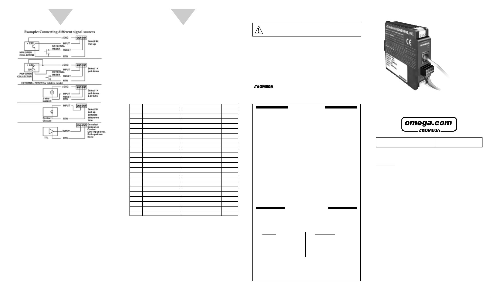
Open Collector NPN (Use software to set: 3 KΩ pull up to 5V):
Max. current source = 1.66 mA
Open Collector PNP (Use software to set: 1KΩ pull down to
RTN): Max. current sink = 12.5 mA
Introduction:
The frequency/pulse signal conditioners are high
performance instruments which operates in 4 different modes.
Input can be programmed to read different signal sources
including low level pulse, open collector and TTL/CMOS
signals. Key features are: programmable excitation and input;
operates as a rate meter, totalizer with reset, A-B totalize and
Quadrature; scalable analog output and a simple RS232
interface for scaling analog output and range selection. The
RS232 interface may also be used for digital transmission of
the input signal to a computer or a PLC. Additional features
include three way isolation between DC power, signal input
and analog output/RS232.
Operation:
Note: When connecting a pulse signal, ensure that the input
signal voltage is less than or equal to the rating. The unit may
be damaged if the input voltage exceeds the maximum rating.
Power Input and Analog Output Setup:
To connect the signal input proceed as follows:
1. Connect a DC power supply with an output voltage
between 10 to 32 Vdc to the signal conditioner (J1).
Note: If power supply used has current limiting, it may not
be able to power the signal conditioners if the available output
voltage is around 10 V, since the peak current may reach
1 to 5 Amps for a few milliseconds.
2. Ensure that if the selected mode or signal source is different
from the default then change them using serial
communication explained later in this manual.
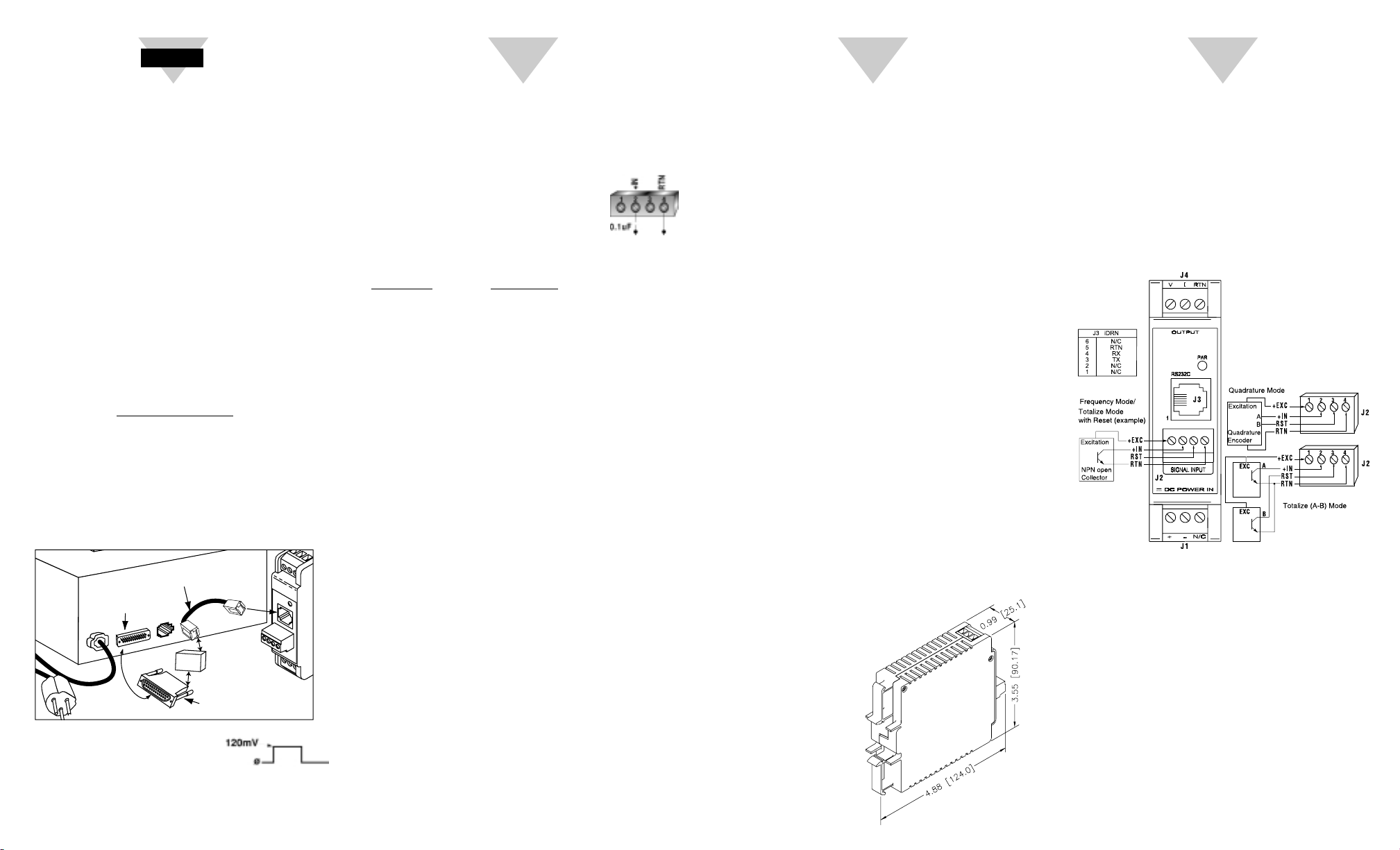
TTL/CMOS Input: (Use software to set: no pull up/down).
Low <= 0.8 V , High >= 3.5 V (For Input: 0.2 Hz to 16 KHz)
Low <= 0.8 V , High >= 12 V ( For Input: 0.2 Hz to 50 KHz )
NAMUR Sensors (Use software to set: 1KΩ pull down to RTN
and 8.2V Excitation.)
For measuring a low level signal riding on top of a large DC
signal, connect a 0.1 uF capacitor. See Detail.
Use software to set 1KΩ pull down to RTN.
OPERATING MODES:
Frequency: Range = 0.2 Hz to 50 KHz
Max. Input Frequency: 30 KHz. for Input
Level: 0-5 V
Max. Input Frequency: 50 KHz. for Input Level: 0-12 V
FREQUENCY RESOLUTION
0 to 9.99999 Hz 0.00001 Hz
10 to 99.9999 Hz 0.0001 Hz
100 to 999.999 Hz 0.001 Hz
1000 to 9999.99 Hz 0.01 Hz
10000 to 50000.0 Hz 0.1 Hz
0 to 50000 Hz 1 Hz
Totalize with Reset: Range = 0 to 999999*, if reading is larger
than 999999, then reading is converted to floating point
number, i.e. 9.99E9 (maximum).
Max. Input Frequency: 30 KHz. for Input Level: 0-5 V
Max. Input Frequency: 50 KHz. for Input Level: 0-12 V
A-B Totalize (Reset input used as +A input): Range = -99999
to 999999*, if reading is larger than 999999, then reading is
converted to floating point number, i.e. -9.99E9 (minimum),
9.99E9 (maximum).
Max. Input Frequency: 30 KHz. for Input Level: 0-5 V
Max. Input Frequency: 25 KHz. for Input Level: 0-12 V
Quadrature (Reset input used as second input): Range =
-99999 to 999999*, if reading is larger than 999999, then
reading is converted to floating point number, i.e. -9.99E9
(minimum), 9.99E9 (maximum).
Max. Input Frequency: 30 KHz. for Input Level: 0-5 V
Max. Input Frequency: 25 KHz. for Input Level: 0-12 V
* Resolution is 1 count.
ISOLATION:
Dielectric strength per 1 minute test based on EN 61010 for
50 Vdc or Vrms working voltage.
Three way Isolation:
• Power to Signal Input: 1800V Peak
• Power to Analog Output/Communication: 1800V Peak
• Signal Input to Analog Output/Communication: 1400V
COMMON MODE REJECTION:
100 dB
INPUT IMPEDANCE:
Input: 1MΩ to +EXC Reset: 100K to +5V
INPUT OVER-VOLTAGE PROTECTION:
With 1K pull down: 14V With 3K pull up: 20V
Without pull up/down: 60V
START HERE
2
3
EXCITATION:
5, 8.2 or 12.5V at 25mA, programmable
ACCURACY AT 25 °C:
± 0.1% of Full scale Crystal time base accuracy: ± 50 ppm
TEMPERATURE STABILITY:
± 50 ppm/°C typical Time base stability: ± 1ppm/°C
STEP RESPONSE FOR RS232 OUTPUT:
0.1 second to 99% of the final value
(Filter time constant = 0, Gate time = 0.05 Sec)
RESPONSE TIME:
To verify the response time, check the carriage return <CR>,
it will be sent at the end of the response. You can send
another command after you receive the <CR>.
i.e. send: *X01 response: X01<DATA><CR>
Note: Only for reading (X01 command).
Frequency mode: response time is controlled by the
gate time. If gate time is increased then response
time is longer.
Other modes: response time is not controlled by the
gate time.
ANALOG OUTPUT STEP RESPONSE TIME:
2 Seconds to 99% of the final value
WARM UP TO RATED ACCURACY:
30 minutes
ANALOG OUTPUT SIGNAL TYPE:
Voltage: 0-10 Volt, maximum current 10mA
Current: 0-20 mA or 4-20 mA, maximum compliance
voltage 10 Volts (maximum loop resistance 500Ω)
ANALOG OUTPUT LINEARITY:
0.1% of FS
INPUT POWER:
10 to 32 Volt DC
POWER CONSUMPTION:
3 Watts (125mA at 24V DC)
OPERATING AMBIENT:
-5 to +55 °C
STORAGE TEMPERATURE:
-40 to +85 °C
RELATIVE HUMIDITY:
90% at 40 °C
non-condensing
DIMENSIONS:
4
COMPUTER
CONNECTION
(DB9 or DB25)
COMPUTER
POWER
CONNECTION
RJ12 CONNECTOR
with CABLE
RS-232 to
RS-485
CONVERTER
HALF-DUPLEX
#CAT-285
ADAPTOR (DB9/25 to RJ12)
#DB9-RJ12, #DB25-RJ12
SIGNAL CONDITIONER MODULE
Page 2
3. Connect the signal input to screw terminal, and ensure that
the screws are tight
4. To view/change the scaling that relates the analog output to
signal input: connect the RS232 output of the signal
conditioner to an available serial port of a computer. The
cable and the DB9 or DB25 connectors are available as an
option.
5. Turn on the computer, start Windows 3.0 or higher and run
the Signal Conditioner Configuration Setup Program.
6. Start the configuration program, you need to indicate which
serial port is to be used for serial communication by checking
the appropriate check box on the opening menu.
Note: It is not necessary to know the serial communication
protocol. i.e. baud rate, parity, 7/8 data bit and stop bit; the
program will determine this information automatically.
However, it is good practice to mark the protocols used on the
signal conditioner label if different from default.
7. Once the program starts it will automatically detect the
signal conditioner configuration and will display a window of
available options. To view the signal input click on the
display on/off.
8. To change analog output scaling choose analog output
scaling and enter the desired values.
9. Once the custom scaling is finished, ensure that Send
Configuration is clicked, otherwise the changes will not take effect.
10. The input/output scaling may be fine tuned, while both
communication and analog output are active. You may make
a change to the analog output in the configuration program,
and watch the DVM connected to analog output of the signal
conditioner follow the new settings.
56
11. You may save or print a particular configuration by
selecting the file menu. It’s always a good practice to both
print and save the scaling of each signal conditioner.
12. If the program is not able to establish communication then
an error message is displayed. This happens either when the
wrong serial port is specified or when the cable is
disconnected.
13. The procedure to disable Continuous Mode and change
the iDRN to Command Mode is as follows:
Using HyperTerminal, or any serial communication program,
type: Ctrl + S
To change the device to Command Mode, type: ^AE
To change the Bus Format Register, type: *W0814
To reset the device,type: *Z01
Cycle power to the unit.
Modbus Register Definition
Reg. # Read Function Write Function # of byte
1 Input Range Input Range 1
2 Input/Output Config. Input/Output Conf. 1
3 Decimal Point Decimal Point 1
4 Filter Time Constant Filter Time Constant 1
5 Reading/Output Scale Not supported 3
6 Reading/Output Offset Not supported 3
7 Comm. Parameters Comm. Parameters 1
8 Comm. Bus Format Comm. Bus Format 1
9 Comm. Data Format Comm. Data Format 1
A Comm. Device Addr. Comm. Device Addr. 1
B Comm. Recog. Char. Comm. Recog. Addr. 1
C Unit of measure Not supported 3
D Gate Time Gate Time 1
E Debounce Time Debounce Time 1
F Transmit Time Transmit Time 2
10 Main Value Hard Reset 3
11 Peak Value Reset Peak 1
12 Valley Value Reset Valley 1
13 Not Supported M.S. bytes Output Scale 2
14 Not Supported L.S. byte Output Scale 1
15 Not Supported M.S. bytes Output Offset 1
16 Not Supported L.S. byte Output Offset 2
Note:
1) Main, Peak, Valley value: 4 bytes will send from the unit
a. Highest byte always 00h.
b. 2nd Highest byte: (MSB is sign (1=negative, 0=positive),
next 3 bits are number of decimal points).
c. Low nibble of second byte, and lowest 2 bytes are the value.
d. The decimal point register has to set to: 1, 2, 3, or 4.
2) Bus Format: Bit 5 1/0 = Modbus/Newport
3) Output Scale/Offset Write:
Due to write single only, two write operation is needed to
write scale/offset, and to make it effective it needs to
follow with Hard Reset command.
4) To configure to Newport protocol, set bit 5 of Bus Format
to low and follow with Hard Reset command.
M2534/0106
, are trademarks of OMEGA Engineering, Inc.
WARNING: These products are not designed for use in, and should not be used
for, patient-connected applications.
WARRANTY/DISCLAIMER
OMEGA ENGINEERING, INC. warrants this unit to be free of defects in materials and
workmanship for a period of 13 months from date of purchase. OMEGA Warranty adds an
additional one (1) month grace period to the normal one (1) year product warranty to cover
handling and shipping time. This ensures that OMEGA’s customers receive maximum
coverage on each product.
If the unit should malfunction, it must be returned to the factory for evaluation. OMEGA’s
Customer Service Department will issue an Authorized Return (AR) number immediately upon
phone or written request. Upon examination by OMEGA, if the unit is found to be defective it will
be repaired or replaced at no charge. OMEGA'S WARRANTY does not apply to defects
resulting from any action of the purchaser, including but not limited to mishandling, improper
interfacing, operation outside of design limits, improper repair, or unauthorized modification. This
WARRANTY is VOID if the unit shows evidence of having been tampered with or shows
evidence of being damaged as a result of excessive corrosion; or current, heat, moisture or
vibration; improper specification; misapplication; misuse or other operating conditions outside of
OMEGA’s control. Components which wear are not warranted, including but not limited to
contact points, fuses, and triacs.
OMEGA is pleased to offer suggestions on the use of its various products. However, OMEGA
neither assumes responsibility for any omissions or errors nor assumes liability for any damages
that result from the use if its products in accordance with information provided by OMEGA, either
verbal or written. OMEGA warrants only that the parts manufactured by it will be as specified and
free of defects. OMEGA MAKES NO OTHER WARRANTIES OR REPRESENTATIONS OF ANY
KIND WHATSOEVER, EXPRESSED OR IMPLIED, EXCEPT THAT OF TITLE, AND ALL IMPLIED
WARRANTIES INCLUDING ANY WARRANTY OF MERCHANTABILITY AND FITNESS FOR A
PARTICULAR PURPOSE ARE HEREBY DISCLAIMED. LIMITATION OF LIABILITY: The
remedies of purchaser set forth herein are exclusive and the total liability of OMEGA with respect
to this order, whether based on contract, warranty, negligence, indemnification, strict liability or
otherwise, shall not exceed the purchase price of the component upon which liability is based. In
no event shall OMEGA be liable for consequential, incidental or special damages.
CONDITIONS: Equipment sold by OMEGA is not intended to be used, nor shall it be used: (1) as a
“Basic Component” under 10 CFR 21 (NRC), used in or with any nuclear installation or activity; or (2)
in medical applications or used on humans. Should any Product(s) be used in or with any nuclear
installation or activity, medical application, used on humans, or misused in any way, OMEGA
assumes no responsibility as set forth in our basic WARRANTY / DISCLAIMER language, and
additionally, purchaser will indemnify OMEGA and hold OMEGA harmless from any liability or
damage whatsoever arising out of the use of the Product(s) in such a manner.
RETURN REQUEST/INQUIRIES
Direct all warranty and repair requests/inquiries to the OMEGA Customer Service Department.
BEFORE RETURNING ANY PRODUCT(S) TO OMEGA, PURCHASER MUST OBTAIN AN
AUTHORIZED RETURN (AR) NUMBER FROM OMEGA’S CUSTOMER SERVICE
DEPARTMENT (IN ORDER TO AVOID PROCESSING DELAYS). The assigned AR number
should then be marked on the outside of the return package and on any correspondence.
The purchaser is responsible for shipping charges, freight, insurance and proper packaging
to prevent breakage in transit.
OMEGA’s policy is to make running changes, not model changes, whenever an improvement
is possible. This affords our customers the latest in technology and engineering.
OMEGA is a registered trademark of OMEGA ENGINEERING, INC.
© Copyright 2006 OMEGA ENGINEERING, INC. All rights reserved.
This document may not be copied, photocopied, reproduced, translated, or reduced to any
electronic medium or machine-readable form, in whole or in part, without prior written
consent of OMEGA ENGINEERING, INC.
FOR WARRANTY RETURNS, please have
the following information available BEFORE
contacting OMEGA:
1. P.O. number under which the product
was PURCHASED,
2. Model and serial number of the product
under warranty, and
3. Repair instructions and/or specific
problems relative to the product.
FOR NON-WARRANTY REPAIRS, consult
OMEGA for current repair charges. Have
the following information available BEFORE
contacting OMEGA:
1. P.O. number to cover the COST of the
repair,
2. Model and serial number of product, and
3. Repair instructions and/or specific
problems relative to the product.
iDRN-FP
Frequency/Pulse Signal Conditioner
This device is marked with the international caution symbol. It is important to
read the Setup Guide before installing or commissioning this device, as the
guide contains important information relating to safety and EMC.
It is the policy of OMEGA to comply with all worldwide safety and EMC/EMI
regulations that apply. OMEGA is constantly pursuing certification of its products to
the European New Approach Directives. OMEGA will add the mark to every
appropriate device upon certification.
The information contained in this document is believed to be correct, but OMEGA
Engineering, Inc. accepts no liability for any errors it contains, and reserves the right
to alter specifications without notice.
PATENT NOTICE: This product is covered by one or more of the following
patents: U.S. Pat. No. Des. 336,895, 5,274,577/ Canada 2052599, 2052600/ Italy
1249456, 1250938/ France Brevet No. 91 12756/ Spain 2039150, 2048066/ UK
Patent No. GB2 249 837, GB2 248 954/ Germany DE 41 34398 C2.
TRADEMARK NOTICE:
®
omega.com
®
®
®
OMEGAnet® On-Line Service
www.omega.com
Servicing North America:
USA:JJ One Omega Drive, P.O. Box 4047
ISO 9001 CertifiedJ Stamford CT 06907-0047
JJ TEL: (203) 359-1660JJ FAX: (203) 359-7700
JJ
Canada: J
JJ Laval (Quebec) H7L 5A1
JJ TEL: (514) 856-6928JJ FAX: (514) 856-6886
JJ
e-mail: [email protected]
976 Bergar
e-mail: [email protected]
For immediate technical or application assistance:
USA and Canada:J Sales Service: 1-800-826-6342 / 1-800-TC-OMEGA
JJ Customer Service: 1-800-622-2378 / 1-800-622-BEST
JJ Engineering Service: 1-800-872-9436 / 1-800-USA-WHEN
Mexico and J TEL: (001)800-TC-OMEGA®J FAX: (001) 203-359-7807
Latin American:J En Espa
JJ
ñol: (001) 203-359-7803J
e-mail: [email protected]
Servicing Europe:
Czech Republic:J Frystatska 184, 733 01 Karviná
JJ TEL: +420 59 6311899JJ FAX: +420 59 6311114
JJ
Germany/Austria:J
JJ TEL: +49 7056 9398-0JJ FAX: +49 7056 9398-29
JJ Toll Free in Germany: 0800 639 7678
JJ
United Kingdom:J
ISO 9002 CertifiedJ River Bend Technology Centre
JJ Northbank, Irlam Manchester M44 5BD United Kingdom
JJ TEL: +44 161 777 6611J FAX: +44 161 777 6622
JJ Toll Free in England: 0800 488 488
JJ
e-mail: [email protected]
Daimlerstrasse 26, D-75392 Deckenpfronn, Germany
e-mail: [email protected]
One Omega Drive
e-mail: [email protected]
Internet e-mail
®
®
®
 Loading...