

Page 1
12.0973.0004
ROTRONIC AG, CH-8303 Bassersdorf
Tel. +41 44 838 11 44, www.rotronic.com
ROTRONIC Messgeräte GmbH, D-76275 Ettlingen
Tel. +49 7243 383 250, www.rotronic.de
ROTRONIC SARL, 56, F - 77183 Croissy Beaubourg
Tél. +33 1 60 95 07 10, www.rotronic.fr
ROTRONIC Italia srl
, I- 20157 Milano
Tel. +39 2 39 00 71 90, www.rotronic.it
ROTRONIC Instruments (UK) Ltd, West Sussex, RH10 9EE
Phone +44 1293 571000, www.rotronic.co.uk
ROTRONIC Instrument Corp, NY 11788, USA
Phone +1 631 427-3898, www.rotronic-usa.com
ROTRONIC Instruments Pte. Ltd., Singapore 159836
Phone +65 6376 2107, www.rotronic.sg
ROTRONIC Shanghai Rep. Office, Shanghai 200233, China
Phone +86 40 0816 2018, www.rotronic.cn
ROTRONIC Canada Inc., Canada L8W 3P7
Phone+ 1 905 754 5164, www.rotronic.ca
AC
DC
AC L
OUT
2
OUT
1
GND
AC
DC
AC L
AC N
OUT 2
OUT 1 GND
High voltage
SHORT INSTRUCTION MANUAL
Digital & analogue Transmitter for Humidity & Temperature
Wall Version
Congratulations on the purchase of your new HygroFlex5-series transmitter. You have bought a
state-of-the-art device. Please read these short instructions carefully before installing the device.
General Description
The HygroFlex5-series devices are universal transmitters for transmission of humidity and temperature measurements. These short instructions are limited to a description of the main functions
and installation of the device. The detailed instruction manual can be found on the internet at:
www.rotronic.com.
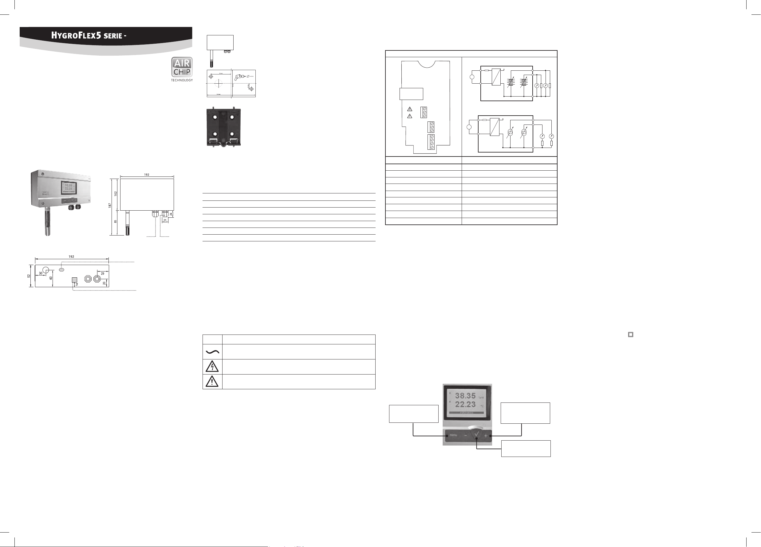
Dimensions / Connections
Mechanical Installation
Wall Version (Type W)
Service Interface
(Mini-USB)
Ethernet Connection
(Optional)
General Recommendations
Relative humidity is extremely temperature-dependent. In order to measure it exactly, the probe and
sensors must be set exactly on the temperature level of the environment that is to be measured.
Follow the guidelines below to ensure optimum performance:
a) Choose a representative position for installation:
Install the probe at a place where the humidity, temperature and pressure conditions are
representative of the environment that is to be measured.
an air velocity of at least 1 meter per second accelerates and facilitates adaptation of the probe
to changing temperatures.
c) Avoid:
1. Probe too close to heating elements, cooling coils, cold or hot walls, direct sunlight, etc.
3. Unstable pressure conditions with high air turbulence.
d) Insert the probe as far as possible into the environment that is to be measured.
e) Avoid accumulation of condensation at the contact wires of the sensor.
Install the probe such that the probe tip points down. If that is not possible, install it in
horizontal position.
Maintenance
a) The device must not come into contact with liquids.
b) Clean the outside of the device by wiping with a moist cloth.
Mounting the Wall Version
Orientation
Mount the transmitter so that the probe points down.
Mounting Variant 1 (Drill Template)
Drill the necessary holes using the drill template drawn on the
packaging. Then insert the plugs delivered with the device and
mount the transmitter with the screws.
wiring diagrams used:
4-wire circuit / HF56x
Voltage output
O
TCP / IP
Sources of Error
Temperature Errors
Adaptation time too short, cold outside wall, heating elements, sunlight, etc.
Humidity Errors
Through vapor, splashed water, dripping water or condensation on the sensor, etc. This does not,
however, impair reproducibility or long-term stability, even when the sensor is exposed to high
humidity or saturation with water vapor (condensation) for a prolonged period.
Contamination
Scaling / Adjustment / Firmware Update
The following settings can be made using the HW4 software and AC3006 or AC3009 service cable:
• rescaling of the outputs
• adjustment
www.rotronic.com.
Periodical Calibration of the Sensor / Transmitter
Both the Pt 100 RTD temperature sensor and the associated electronics are very stable and do not
normally need to be changed or calibrated after calibration in the factory. The long-term stability
of the ROTRONIC Hygromer humidity sensor is typically better than 1 %RH per year. For maximum
precision, we recommend calibration of the sensors approximately every six to twelve months. In the
case of applications in which the sensor is subjected to pollutants, more frequent calibration may
be necessary. Calibration can be carried out by the user onsite, or in the laboratory or workshop.
For routine calibrations the probe should be checked at one or two points.
checked easily using a probe simulator in the HW4 software. The electronics cannot be repaired in
calibration, we refer to the full version of the user manual, available on the internet.
Technical Data (Measurement)
Humidity 0...100 %RH
Temperature Probe-dependent
Accuracy Probe-dependent
Interfaces UART (<5 V, <10 mA )
RS-485 (<10.5 V , < 10 mA )
Ethernet (per IEEE 802.3)
Technical Data (Operation)
Temperature –10...50 °C *
Humidity 0...100 %RH, non-condensing
Indoor use only
Protection IP65 except for models with Ethernet interface
Supply voltage 100-240 VAC / 50-60 Hz
Power consumption 5 W
Fuse T2AL 250 VAC
Permitted pollution degree 2
Maximum altitude 2000 MASL
Protection class II
* Only the transmitter can be used in this environment. The porbe must be mounted in the
Mounting Variant 2 (DIN Top-Hat Rail)
If there is a TS35 DIN top-hat rail available, the transmitter can be
clipped on to the top-hat rail directly with the help of the mounting kit
AC5002 (available as optional extra). The DIN holders (one package
unit contains 2 holders and 8 screws) are screwed directly on to the
pre-drilled holes of the transmitter for this.
AC N
AC L
1
2
3
OUT1
OUT2
GND
GND
GND
1
2
D +
3
D –
1
2
3
4
O
Current output
Electrical Installation
Power Supply
4-wire with analog outputs: 100 to 240 VAC.
With both output circuits closed, the maximum current consumption is 50 mA.
Supply Voltage / Technology
Type Supply Voltage V+ Load Output
4-wire
HF561 100…240 VAC Max. 500 Ω 0...20 mA (<15 V)
HF562 100…240 VAC Max. 500 Ω 4...20 mA (<15 V))
HF563 100…240 VAC Min. 1000 Ω 0...1 V
HF564 100…240 VAC Min. 1000 Ω 0...5 V
SignalPower Supply
HF565 100…240 VAC Min. 1000 Ω 0...10 V
Caution: Please follow the instructions in the user guide. Wrong supply voltages and
excessive loads on the outputs can damage the transmitter.
A
The device must be installed by a skilled electrician.
A suitable power connection cable must be used:
- Recommended power cable H05 V V-F Helukabel
- Power & signal cable Ø 6-8 mm
- Max. wire cross section 2.5 mm
2
- Tightening torque 3-5 Nm
It must not be possible to loosen the cable glands again by hand after installation.
The device does not have a mains power switch. This switch must be provided outside
the device at an accessible point and marked accordingly.
The device is only safe if the information and instructions in the manual are followed.
Symbol Explanation
Alternating current
Caution! Electric shock!
Terminal Description
AC N Power Supply Neutral
AC L Power Supply Phase / Phase Conductor
GND RS-485 Ground
D+ RS-485 Bi-directional TX+ / RX +
D– RS-485 Bi-directional TX– / RX –
OUT1 Analog humidity output
OUT2 Analog temperature output
GND Ground
GND Ground
Caution: The connections OUT1, OUT2, GND, D+ and D– as well as the USB and Ethernet
A
connections may only be connected with adequate separate secondary current circuits. The terminals OUT1, OUT2, GND, D+ and D– may not be connected with mains
power supply. Make sure that everything has been connected correctly and that all
settings have been made correctly before integrating and connecting the transmitter
in the network.
Programming
The initial settings of the units are made in the factory to your order. The transmitters are adjusted
in the factory, so checking and readjustment at installation time are not necessary. The units can
be put into operation immediately after installation.
Display
when a button is pressed.
It is possible to change between a two-line or three-line display by pressing the Enter button.
Increase value / Display line up
:
+
Decrease value / Display line down
:
–
When there is an alarm, "Sensor Alarm" is shown at the bottom display edge.
It is possible to choose between metric or English system units.
Consult manual
MENU button
Open / Close menu
Menu Navigation
Buttons + / – change value increase / decrease
ENTER button
Select menu point
Note: Unauthorized use of the menu can be prevented by locking the setting “Display Menu”
(using the HW4 software > Device Manager > Display).
Page 2

12.0973.0004
ROTRONIC AG, CH-8303 Bassersdorf
Tel. +41 44 838 11 44, www.rotronic.com
ROTRONIC Messgeräte GmbH, D-76275 Ettlingen
Tel. +49 7243 383 250, www.rotronic.de
ROTRONIC SARL, 56, F - 77183 Croissy Beaubourg
Tél. +33 1 60 95 07 10, www.rotronic.fr
ROTRONIC Italia srl
, I- 20157 Milano
Tel. +39 2 39 00 71 90, www.rotronic.it
ROTRONIC Instruments (UK) Ltd, West Sussex, RH10 9EE
Phone +44 1293 571000, www.rotronic.co.uk
ROTRONIC Instrument Corp, NY 11788, USA
Phone +1 631 427-3898, www.rotronic-usa.com
ROTRONIC Instruments Pte. Ltd., Singapore 159836
Phone +65 6376 2107, www.rotronic.sg
ROTRONIC Shanghai Rep. Office, Shanghai 200233, China
Phone +86 40 0816 2018, www.rotronic.cn
ROTRONIC Canada Inc., Canada L8W 3P7
Phone+ 1 905 754 5164, www.rotronic.ca
AC
DC
AC L
OUT
2
OUT
1
GND
AC
DC
AC L
AC N
OUT 2
OUT 1 GND
High voltage
KURZBEDIENUNGSANLEITUNG
Digitaler & analoger Messumformer
für Feuchte- und Temperatur
Wandversion
Herzlichen Glückwunsch zum Kauf Ihres neuen HygroFlex5-Serie Messumformers. Sie haben
damit ein dem neuesten Stand der Technik entsprechendes Gerät erworben. Bitte lesen Sie diese
Anleitung genau durch, bevor Sie das Gerät installieren.
Allgemeine Beschreibung
Die HygroFlex5-Serie Geräte sind universelle Messumformer, für die Übertragung von Feuchte- und
Temperaturmesswerten. Diese Kurzbedienungsanleitung beschränkt sich auf die Beschreibung
der wichtigsten Funktionen und der Installation des Gerätes. Die detaillierte Bedienungsanleitung
www.rotronic.com
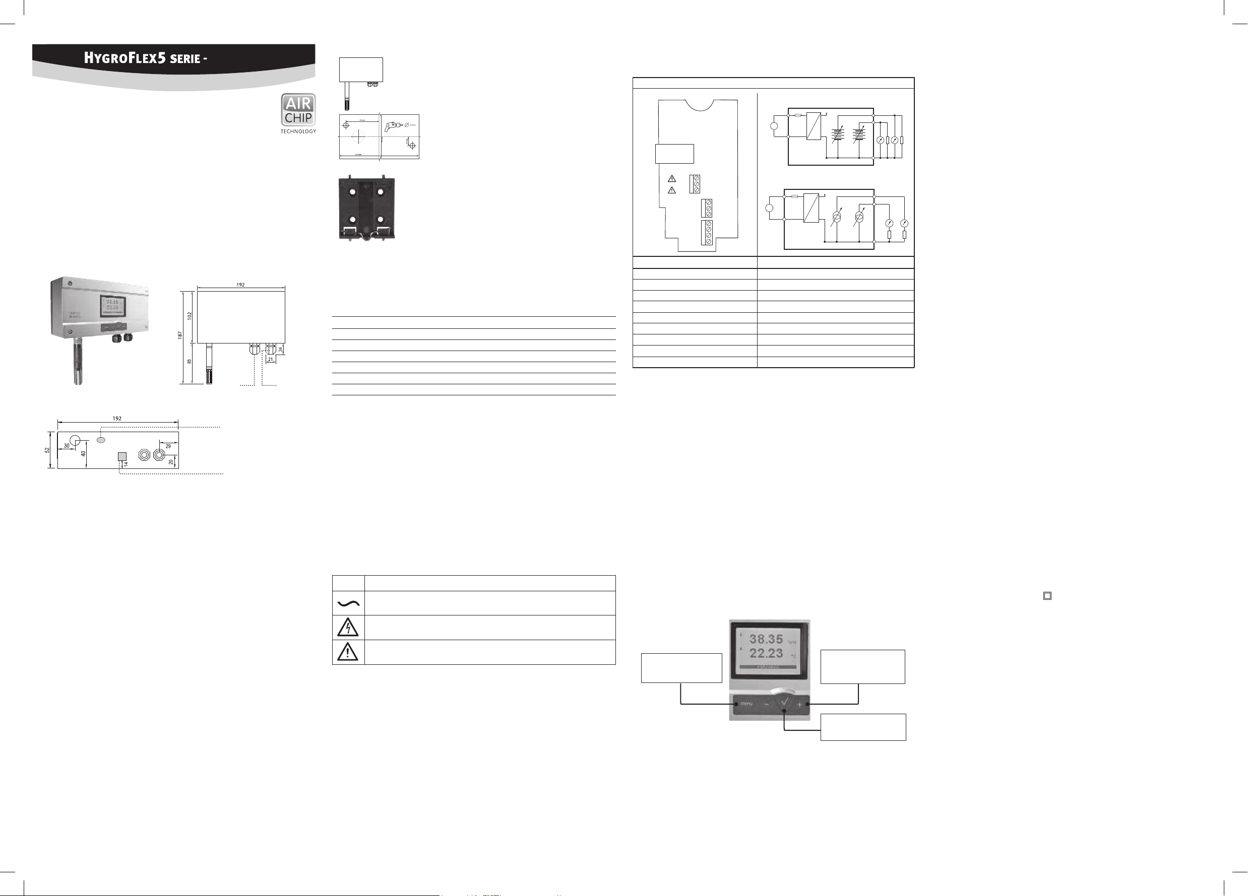
Abmessungen / Anschlüsse
Wandausführung (Typ W)
Service Schnittstelle
(Mini-USB)
Ethernet Anschluss
(optional)
Mechanische Installation
Allgemeine Empfehlungen
Die relative Feuchte ist extrem temperaturabhängig. Deren exakte Messung erfordert, dass Fühler
und der Sensor genau auf dem Temperaturniveau der zu messenden Umgebung sind. Daher kann
Die Einhaltung der folgenden Richtlinien garantiert Ihnen eine optimale Leistung des Gerätes:
a) Wählen Sie einen repräsentativen Installationsort:
Installieren Sie den Fühler an einem Ort, wo die Feuchte-, Temperatur- und Druckverhältnisse
für die zu messende Umgebung repräsentativ sind.
b) Stellen Sie genügend Luftbewegung am Fühler sicher:
Eine Luftgeschwindigkeit von mindestens 1 Meter/Sekunde beschleunigt und erleichtert die
Anpassung des Fühlers an wechselnde Temperaturen.
c) Zu vermeiden sind:
1. Fühler zu nahe an Heizelement, Kühlschlange, kalter oder warmer Wand und direkte
Sonneneinstrahlung etc.
2. Fühler zu nahe an Dampf-Injektor, Befeuchter oder direkter Niederschlag.
3. Unstabile Druckverhältnisse bei grossen Luftturbulenzen.
d) Tauchen Sie den Fühler so weit als möglich in die zu messende Umgebung ein.
e) Vermeiden Sie die Ansammlung von Kondensat an den Kontaktdrähten des Sensors.
Installieren Sie den Fühler so, dass die Fühlerspitze nach unten zeigt. Wenn dies nicht
möglich ist, installieren Sie ihn in horizontaler Position.
Wartung
a) Das Gerät darf nicht mit Flüssigkeiten in Kontakt kommen.
b) Reinigen Sie die Gerätaussenseite durch abwischen mit einem feuchten Tuch.
Montage der Wandversion
Ausrichtung
Der Transmitter wird so montiert, dass der Fühler
nach unten gerichtet ist.
Montage Variante 1 (Bohrschablone)
Mit der auf der Verpackung aufgezeichneten Bohrschablone werden
die nötigen Löcher gebohrt. Danach werden die mitgelieferten
Dübel eingesetzt um dann den Transmitter mit Hilfe der Schrauben
zu montieren.
Klemmenbelegung / Anschlussschemata
Anschluss-Schemas verwenden zu können:
4-Leiter Schaltung / HF56x
Spannungsausgang
O
TCP / IP
Fehlerquellen
Temperaturfehler
Durch zu kurze Angleichzeit, kalte Aussenwand, Heizkörper und Sonneneinstrahlung usw.
Feuchtefehler
Durch Dampf, Wasserspritzer, Tropfwasser oder Kondensation am Sensor usw. Jedoch wird die
Reproduzierbarkeit und Langzeitstabilität dadurch nicht beeinträchtigt, auch wenn der Fühler über
längere Zeit einer hohen Feuchte oder Sättigung mit Wasserdampf (Kondensation) ausgesetzt wurde.
Verschmutzung
Messortes und ist periodisch zu reinigen oder zu ersetzen.
Skalierung / Justierung / Firmware update
Montage Variante 2 (DIN-Hutschine)
Bei vorhanden DIN-Hutschienen TS35 kann unter Mithilfe des
Montagekit AC5002 (optional erhältlich) der Transmitter direkt auf
die DIN Hutschienen aufgeschnappt werden. Hierzu werden die
DIN-Halterungen (Eine Verpackungseinheit besteht aus 2 Halterungen und 8 Schrauben) direkt auf die vorgebohrten Löcher des
Transmitters geschraubt.
AC N
AC L
1
2
3
OUT1
OUT2
GND
GND
GND
1
2
D +
3
D –
1
2
3
4
O
Stromausgang
Elektrische Installation
Stromversorgung
4-Leiter mit Analogausgängen: 100 bis 240 VAC.
Mit beiden Ausgängen angeschlossen beträgt die maximale Stromaufnahme 50 mA.
Versorgungsspannung / Technologie
Typ Spannungsversorgung V+ Bürde Ausgang
4 Leiter
HF561 100…240 VAC Max. 500 Ω 0...20 mA (<15V)
HF562 100…240 VAC Max. 500 Ω 4...20 mA (<15V)
HF563 100…240 VAC Min. 1000 Ω 0...1 V
HF564 100…240 VAC Min. 1000 Ω 0...5 V
HF565 100…240 VAC Min. 1000 Ω 0...10 V
SignalSpeisung
Achtung: Bitte beachten sie das Benutzerhandbuch. Falsche Versorgungsspannungen
sowie zu grosse Belastungen der Ausgänge können den Messumformer beschädigen.
A
Die Installation des Geräts muss von einer elektrotechnischen Fachkraft vorgenommen
werden.
Es ist darauf zu achten, eine geeignete Netzanschlussleitung zu verwenden:
- Empfehlung Netzkabel H05 V V-F Helukabel
- Netz-& Signalkabel Ø 6-8mm
- Max Litzenquerschnitt 2,5 mm
2
- Anzug Drehmoment 3-5 Nm
Die Kabelverschraubungen dürfen nach der Installation nicht mehr von Hand gelöst
werden können.
Das Gerät verfügt über keinen Netzschalter. Dieser muss ausserhalb des Geräts vorhanden, leicht zugänglich und gekennzeichnet sein.
Die Sicherheit des Gerätes ist nur bei Einhaltung der im Handbuch beschriebenen
Hinweise gewährleistet.
Symbol Erläuterung
Wechselstrom
Klemme Beschreibung
AC N Spannungsversorgung Neutral
AC L Spannungsversorgung Phase / Aussenleiter
GND RS-485 Ground
D+ RS-485 Bi-directional TX+ / RX +
D– RS-485 Bi-directional TX– / RX –
OUT1 Feuchte-Analogausgang
OUT2 Temperatur-Analogausgang
GND Ground
GND Ground
Achtung: Die Anschlüsse OUT1, OUT2, GND, D+ und D– sowie der USB und Ethernet-
A
Anschluss dürfen nur mit ausreichend getrennten Sekundärstromkreisen verbunden
werden. Die Klemmen OUT1, OUT2, GND, D+ und D– dürfen nicht mit Netzspannung
angeschlossen werden. Stellen Sie sicher, dass bevor Sie den Transmitter ins Netzwerk
einbinden und anschliessen, alles richtig verdrahtet wurde und alle Einstellungen
richtig durchgeführt wurden.
Programmierung
Die Grundeinstellungen der Geräte werden im Werk, gemäss Ihrer Bestellung, vorgenommen.
Die Transmitter werden im Werk justiert, sodass eine Überprüfung oder Nachjustierung bei
der Installation nicht notwendig ist. Die Geräte können sofort nach der Installation in Betrieb
genommen werden.
Display
Das LC-Display hat eine Hintergrundbeleuchtung welche so eingestellt werden kann, dass diese
entweder immer an, immer aus ist oder durch drücken einer Taste kurzzeitig aktiviert wird.
Beim Betätigen der Enter-Taste kann zwischen Zwei- oder Dreizeilen Anzeige gewechselt werden.
Im Display können zusätzlich die Mess-End-Indikatoren für jeden Wert angezeigt werden:
Wert erhöhen / Displayzeile nach oben
:
+
Wert verringern / Displayzeile nach unten
:
–
Bei einem Alarm wird „Sensor Alarm“ im unteren Displayrand angezeigt.
Systemeinheiten können Metrisch oder Englisch gewählt werden.
Mit Hilfe der HW4 Software und dem Servicekabel AC3006 oder AC3009 können folgende
Einstellungen durchgeführt werden:
• Neuskalierung der Ausgänge
• Justierung
• Firmware update
www.rotronic.com herunterladen können.
Periodische Kalibrierung des Fühlers / Transmitters
Sowohl der Pt 100 RTD Temperatursensor als auch die dazugehörende Elektronik sind sehr stabil
und müssen nach der Werkskalibrierung normalerweise nicht verändert oder kalibriert werden.
Die Langzeitstabilität der ROTRONIC Hygromer Feuchtefühler ist typischerweise besser als 1 %rF
pro Jahr. Für eine maximale Genauigkeit empfehlen wir eine Kalibrierung der Fühler ca. alle sechs
Kalibrierung notwendig sein. Die Kalibrierung kann durch den Benutzer selber vor Ort oder im
Labor bzw. in der Werkstatt vorgenommen werden. Für Routine- Kalibrierungen sollte der Fühler
an einem oder zwei Punkten geprüft werden.
Die Elektronik des Transmitters selber erfordert normalerweise keine Kalibrierung im Feld. Sie
kann mit der Verwendung eine Fühlersimulators der HW4 Software auf einfache Weise überprüft
werden. Die Elektronik lässt sich nicht im Feld reparieren und sollte bei Problemen ans Herstellerwerk retourniert werden. Für die Details der Kalibrierung verweisen wir auf die Vollversion des
Bedienerhandbuches, welche im Internet erhältlich ist.
Technische Daten (Messbereich)
Feuchte 0...100 %rF
Temperatur Fühlerabhängig
Genauigkeit Fühlerabhängig
Schnittstellen UART (<5V, <10mA )
RS-485 (<10,5V , < 10mA )
Ethernet (gemäs IEEE 802.3)
Technische Daten (Einsatzbereich)
Temperatur –10...50 °C *
Feuchte 0...100 %rF, nicht kondensierend
Verwendung ausschliesslich in Innenräumen
Schutzart IP65 ausser Modelle mit Ethernet Schnittstelle
Versorgungsspannung 100-240 VAC / 50-60 Hz
Leistungsaufnahme 5 W
Sicherung T2AL 250 VAC
Überspannungskategorie II
Erlaubter Verschmutzungsgrad 2
Maximale Einsatzhöhe 2000 m.ü.M.
Schutzklasse II
* Nur das Gerät kann in dieser Umgebung verwendet werden. Der Fühler selber muss ihn dem
Vorsicht! Elektrischer Schock!
Manual konsultieren
Menü öffnen /schliessen
Taste MENU
Menünavigation
Tasten + / – Wert ändern
Erhöhen / Verringern
Taste ENTER
Auswahl Menüpunkt
Hinweis: Der unbefugte Zugriff auf das Menü kann durch Sperren der Einstellung “Display Menü”
verhindert werden (Verwendung der HW4-Software > Geräte-Manager > Display)
Page 3
12.0973.0004
ROTRONIC AG, CH-8303 Bassersdorf
Tel. +41 44 838 11 44, www.rotronic.com
ROTRONIC Messgeräte GmbH, D-76275 Ettlingen
Tel. +49 7243 383 250, www.rotronic.de
ROTRONIC SARL, 56, F - 77183 Croissy Beaubourg
Tél. +33 1 60 95 07 10, www.rotronic.fr
ROTRONIC Italia srl
, I- 20157 Milano
Tel. +39 2 39 00 71 90, www.rotronic.it
ROTRONIC Instruments (UK) Ltd, West Sussex, RH10 9EE
Phone +44 1293 571000, www.rotronic.co.uk
ROTRONIC Instrument Corp, NY 11788, USA
Phone +1 631 427-3898, www.rotronic-usa.com
ROTRONIC Instruments Pte. Ltd., Singapore 159836
Phone +65 6376 2107, www.rotronic.sg
ROTRONIC Shanghai Rep. Office, Shanghai 200233, China
Phone +86 40 0816 2018, www.rotronic.cn
ROTRONIC Canada Inc., Canada L8W 3P7
Phone+ 1 905 754 5164, www.rotronic.ca
AC
DC
AC L
OUT
2
OUT
1
GND
AC
DC
AC L
AC N
OUT 2
OUT 1 GND
High voltage
MODE D'EMPLOI ABRÉGÉ
Transmetteur de mesure numérique & analogique
pour humidité et température.
Version murale
Nous vous félicitons d’avoir choisi le nouveau transmetteur de la série HygroFlex5. Vous avez fait
l’acquisition d’un appareil doté de la technologie la plus récente. Nous vous remercions de lire
ce mode d’emploi avant d’installer votre transmetteur.
Description générale
Les appareils de la série HygroFlex5 sont des transmetteurs de mesure universels pour la transmission de valeurs de mesure d’humidité et de température. Ce mode d’emploi abrégé se limite à
la description des fonctions essentielles de cet appareil. Vous trouverez un mode d’emploi détaillé
sur notre site Internet: www.rotronic.com
Dimensions / raccordements
Version murale (type W)
Interface de service
(mini USB)
Raccordement Ethernet
(En option)
Installation mécanique
Recommandations générales
L’humidité relative dépend très fortement de la température. Pour la précision de sa mesure, le
capteur et les éléments sensibles doivent être réglés exactement sur le niveau de température de
les performances de l’appareil. Le respect des directives suivantes vous garantit des performances
optimales de l’appareil :
a) Choisissez un site d’installation représentatif :
Installez le capteur à un endroit où les conditions d’humidité, de température et de pression
sont représentatives de l’environnement à mesurer.
une vitesse d’air d’au moins 1 mètre/seconde accélère et facilite l’adaptation du capteur aux
changements de température.
c) À éviter:
1. Capteur trop près d’éléments de chauffage, serpentins de refroidissement, mur froid ou
chaud, exposition directe aux rayons solaires etc.
directes.
3. Conditions de pression instables en cas de fortes turbulences d’air.
d) Le capteur aussi loin que possible dans l’environnement à mesurer.
e) Évitez les accumulations de condensation sur les câbles de contact de l’élément sensible.
Installez le capteur de telle sorte que sa pointe soit dirigée vers le bas. Si cela n’est pas
possible, installez-le à l’horizontale.
Entretien
a) L’appareil ne doit pas être mis en contact avec des liquides.
b) Nettoyer l’appareil en l’essuyant avec un chiffon humide.
Montage de la version murale
Orientation
Le transmetteur est monté de façon à ce que
le capteur soit dirigé vers le bas.
Affectation des bornes / schémas de raccordement
schémas de raccordement suivants :
Branchement 4 conducteurs / HF56x
Sources d’erreur
Les valeurs mesurées peuvent être faussées par les causes suivantes:
Erreur de température
Causée par un temps d’égalisation trop court, des murs extérieurs froids, radiateurs, rayonnements du soleil etc.
Version de montage 1 (gabarit de perçage)
les trous nécessaires. Ensuite, mettre en place les chevilles fournies
pour monter le transmetteur de mesure à l’aide des vis.
TCP / IP
Sortie en tension
O
Erreur d’humidité
Causée par la vapeur, les projections d’eau, l’eau d’égouttage ou la condensation sur l’élément
sensible, etc. Cependant, la reproductibilité et la stabilité à long terme ne sont pas affectées par ces
facteurs, même si le capteur a été exposé relativement longtemps à une forte humidité ou saturation
de vapeur d’eau (condensation).
Encrassement
capteur doit être périodiquement nettoyé ou remplacé.
1
Si des embases de rail DIN TS35 sont déjà en place, il est possible
de clipser directement le transmetteur sur celle-ci à l’aide du kit de
sur les trous préperforés du transmetteur de mesure.
AC N
AC L
2
3
OUT1
OUT2
GND
GND
GND
1
2
D +
3
D –
1
2
3
4
O
Installation électrique
Alimentation électrique
4 conducteurs avec sorties analogiques : 100 à 240 VCA.
La consommation maximale en courant avec les deux sorties connectées est de 50mA.
Tension d’alimentation / technologie
Type Alimentation en tension V+ Charge Sortie
4 conducteurs
HF561 100…240 VCA Max. 500 Ω 0...20 mA (<15V)
HF562 100…240 VCA Max. 500 Ω 4...20 mA (<15V)
HF563 100…240 VCA Min. 1000 Ω 0...1 V
HF564 100…240 VCA Min. 1000 Ω 0...5 V
SignalAlimentation
HF565 100…240 VCA Min. 1000 Ω 0...10 V
Attention : veuillez tenir compter des indications du manuel d’utilisation. Des tensions
d’alimentation incorrectes ainsi que des sollicitations trop fortes des sorties peuvent
A
endommager le transmetteur de mesure.
L’installation de l’appareil doit être effectuée par un électrotechnicien professionnel.
Il convient de veiller à utiliser une ligne de raccordement à l’alimentation adéquate :
- Câble d’alimentation conseillé H05 V V-F Helukabel
- Câbles réseau et de signal Ø 6-8mm
- Section maximale des torons 2,5 mm
2
- Couple de serrage 3-5 Nm
Les visseries de câble ne doivent plus être desserrées à la main après l’installation.
L’appareil ne dispose pas d’un interrupteur d’alimentation. Celui-ci doit être externe
à l’appareil, facilement accessible et marqué.
La sécurité de l’appareil n’est garantie que si les recommandations indiquées dans
le manuel d’utilisation sont respectées.
Symbole Explication
Courant alternatif
Borne Description
AC N Tension d’alimentation neutre
AC L Tension d’alimentation phase / ligne extérieure
GND RS-485 terre
D+ RS-485 bidirectionnel TX+ / RX +
D– RS-485 bidirectionnel TX / RX –
OUT1 Sortie analogique d’humidité
OUT2 Sortie analogique de température
GND Terre
GND Terre
Attention: les raccordements OUT1, OUT2, GND, D+ et D– ainsi que les raccordements
A
électriques secondaires séparés. Les bornes OUT1, OUT2, GND, D+ et D– ne doivent
pas être connectées à une tension d’alimentation. Assurez-vous que les connexions
et tous les réglages ont été effectués correctement, avant d’intégrer le transmetteur
de mesure au réseau et de le raccorder, .
Programmation
Les réglages de base des appareils sont effectués en usine conformément à votre commande. Les
de l’installation n’est pas nécessaire. Les appareils peuvent être mis en service immédiatement
après l’installation.
allumé, soit toujours éteint ou à être brièvement activé sur pression d’une touche.
:
+
:
–
Les unités du système peuvent être exprimées en mode métrique ou anglais.
Sortie en courant
Changement d’échelle / ajustage / mise à jour du logiciel interne
Le logiciel HW4 et le câble de service AC3006 ou AC3009 permettent de réaliser les réglages
suivants:
• Changement d’échelle des sorties
• Ajustage
• Mise à jour du logiciel interne
Vous trouverez une description détaillée dans le manuel que vous pouvez télécharger sous
www.rotronic-humidity.com
Étalonnage périodique du capteur / transmetteur de mesure
L’élément sensible de température Pt 100 RTD ainsi que l’électronique correspondante sont très
La stabilité à long terme des capteurs pour l’humidité Hygromer de ROTRONIC est typiquement
inférieure à 1 %HR par an. Pour une précision maximale, nous recommandons un étalonnage du
capteur tous les six à douze mois. Dans des environnements où l’élément sensible est soumis à
des polluants, un étalonnage plus fréquent peut s’avérer nécessaire. L’utilisateur peut réaliser
l’étalonnage lui-même sur site, dans un laboratoire ou un atelier. Pour les étalonnages de routine,
les capteurs devraient être testés sur un ou deux points.
L’électronique du transmetteur ne nécessite normalement pas d’étalonnage sur site. Elle peut être
être réparée sur site et doit être retournée au fabricant en cas de problème. Pour plus de détails
sur le processus d’étalonnage, veuillez consulter le manuel d’utilisation complet, disponible au
téléchargement sur Internet.
Caractéristiques techniques (Gamme de mesure)
Humidité 0…100 %HR
Température Selon le capteur
Précision: Selon le capteur
Interfaces UART (<5V, <10mA )
RS-485 (<10,5V , < 10mA )
Ethernet (selon IEEE 802.3)
Caractéristiques techniques (domaine d’utilisation)
Température –10...50 °C *
Humidité 0...100 %HR, sans condensation
Utilisation uniquement en intérieur
Type de protection IP65 sauf modèles avec interface Ethernet
Tension d’alimentation 100-240 VCA / 50-60 Hz
Puissance absorbée 5 W
Fusible T2AL 250 VCA
Catégorie de surtension II
Degré d’encrassement admissible 2
Altitude d’installation maximale 2000 m au-dessus du niveau de la mer
Classe de protection II
* Seul l'appareil peut être utilisé dans cet environnement. Le capteur lui-même doit être monté
Attention ! Choc électrique !
Consulter le manuel
Touche MENU
ouvrir / fermer le menu
Nav. dans le menu
valeur augmenter / réduire
Touche ENTER
Sélection élément de menu
Remarque: l’accès non autorisé au menu peut être empêché en bloquant le réglage
Page 4
12.0973.0004
ROTRONIC AG, CH-8303 Bassersdorf
Tel. +41 44 838 11 44, www.rotronic.com
ROTRONIC Messgeräte GmbH, D-76275 Ettlingen
Tel. +49 7243 383 250, www.rotronic.de
ROTRONIC SARL, 56, F - 77183 Croissy Beaubourg
Tél. +33 1 60 95 07 10, www.rotronic.fr
ROTRONIC Italia srl
, I- 20157 Milano
Tel. +39 2 39 00 71 90, www.rotronic.it
ROTRONIC Instruments (UK) Ltd, West Sussex, RH10 9EE
Phone +44 1293 571000, www.rotronic.co.uk
ROTRONIC Instrument Corp, NY 11788, USA
Phone +1 631 427-3898, www.rotronic-usa.com
ROTRONIC Instruments Pte. Ltd., Singapore 159836
Phone +65 6376 2107, www.rotronic.sg
ROTRONIC Shanghai Rep. Office, Shanghai 200233, China
Phone +86 40 0816 2018, www.rotronic.cn
ROTRONIC Canada Inc., Canada L8W 3P7
Phone+ 1 905 754 5164, www.rotronic.ca
AC
DC
AC L
OUT
2
OUT
1
GND
AC
DC
AC L
AC N
OUT 2
OUT 1 GND
High voltage
MANUALE D'ISTRUZIONI BREVE
Trasmettitori digitali & anologica per umidità e temperatura
Versione da parete
Ci congratuliamo per il Vostro acquisto di un nuovo trasmettitore della serie HygroFlex5. Avete
acquistato uno strumento al passo con le tecnologie più moderne. Prima di installare lo strumento,
si prega di leggere la presente guida rapida.
Descrizione generale
Gli apparecchi della serie HygroFlex5 sono trasmettitori universali, per la trasmissione di valori
di umidità e temperatura. Il presente manuale d'istruzioni breve si limita a descrivere le funzioni
principali dello strumento e la sua installazione. Le istruzioni d’uso dettagliate sono disponibili
in Internet all’indirizzo: www.rotronic.com
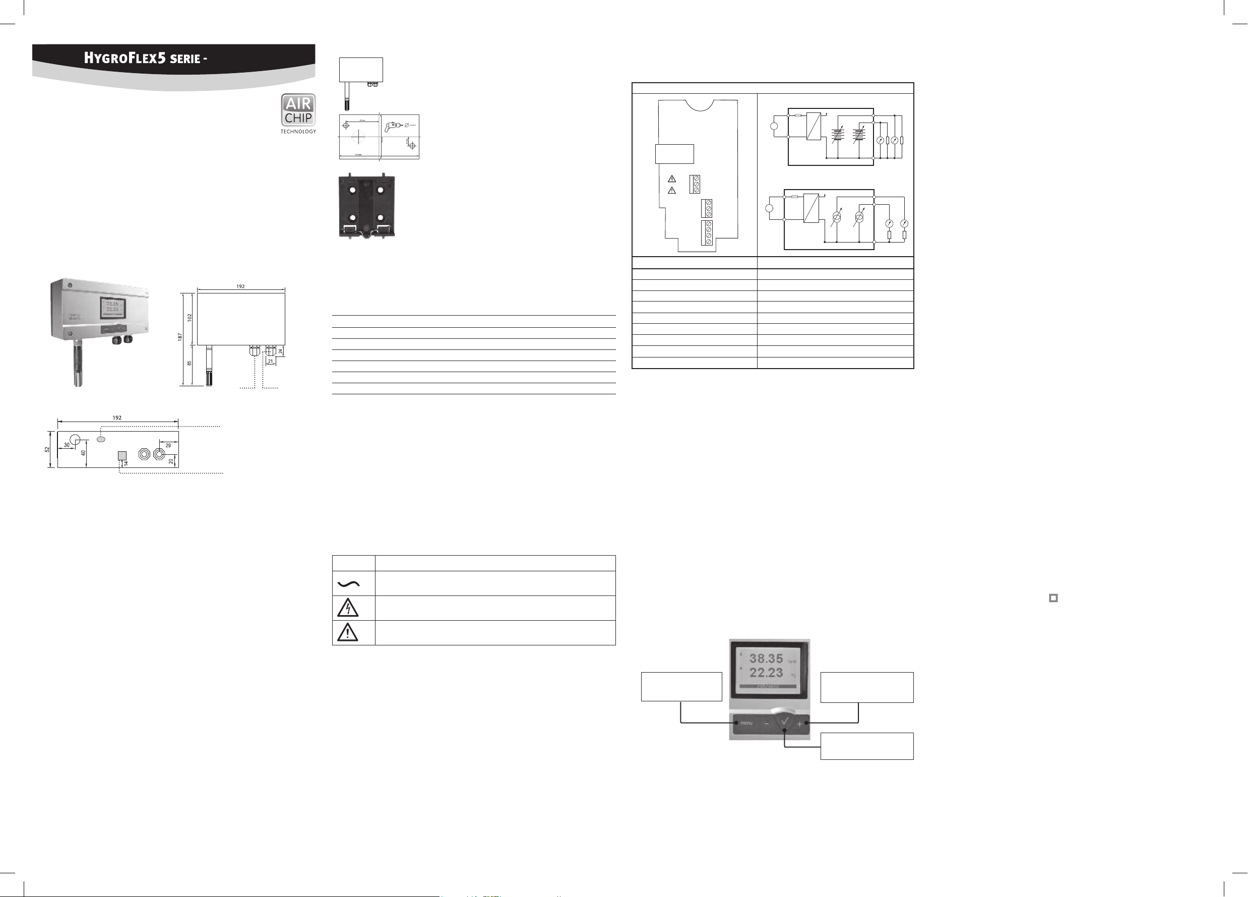
Dimensioni / connessioni
Versione a parete (Tipo W)
Interfaccia di servizio
(mini USB)
Connessione Ethernet
(optional)
Installazione meccanica
Consigli generici
L’umidità relativa dipende direttamente dalla temperatura. La sua misurazione esatta richiede che
sonda e sensori abbiano esattamente la stessa temperatura dell’ambiente da misurare. Pertanto la
sede di installazione scelta ha un ruolo decisivo per il rendimento dello strumento. Per ottenere un
rendimento ottimale dello strumento si devono assolutamente rispettare le seguenti prescrizioni:
a) Scegliere un punto di installazione rappresentativo:
Installare la sonda in un punto in cui le condizioni di umidità, temperatura e pressione siano
rappresentative dell’ambiente che si intende misurare.
Una velocità dell’aria di almeno 1 metro/secondo accelera e facilita l'adattamento della sonda
alle variazioni di temperatura.
c) Condizioni da evitare:
1. Sonda troppo vicina a elementi riscaldanti, serpentine di raffreddamento, pareti fredde o
calde, esposizione diretta ai raggi solari ecc.
3. Rapporti di pressione instabili con eccessive turbolenze dell’aria.
d) Inserire il più possibile la sonda nell’ambiente che si intende misurare.
Installare la sonda in modo che la punta sia rivolta verso il basso. Nel caso non sia possibi-
le, installarla in posizione orizzontale.
Manutenzione
a) Lo strumento non deve entrare in contatto con liquidi.
Montaggio della versione per pareti
Orientamento
Il trasmettitore va montato in modo che la sonda
sia rivolta verso il basso.
Variante 1 di montaggio (sagoma di foratura)
Utilizzando la sagoma di foratura facente parte della confezione si
effettuano i fori necessari. In seguito si inseriscono i tasselli facenti
parte della fornitura per poi montare il trasmettitore avvitandolo.
Variante 2 di montaggio (barra DIN con guida a omega)
Se sono presenti le barre DIN con guida a omega TS35, utilizzando il
kit di montaggio AC5002 (opzionale) è possibile montare a scatto il
trasmettitore direttamente sulle barre DIN. A tal scopo si avviteranno
direttamente sui fori prestampigliati del trasmettitore i supporti DIN
(una confezione contiene 2 supporti e 8 viti).
Installazione elettrica
Alimentazione di corrente
Con entrambe le uscite collegate, l’assorbimento di corrente massimo corrisponde a 50mA.
Tensione di alimentazione / tecnologia
Tipo Alimentazione di tensione V+ Carico Uscita
HF561 100…240 VAC Max. 500 Ω 0...20 mA (<15V)
HF562 100…240 VAC Max. 500 Ω 4...20 mA (<15V)
HF563 100…240 VAC Min. 1000 Ω 0...1 V
HF564 100…240 VAC Min. 1000 Ω 0...5 V
SegnaleAlimentazione
HF565 100…240 VAC Min. 1000 Ω 0...10 V
Attenzione: si prega di rispettare il manuale utente. Tensioni di alimentazione errate
o carichi eccessivi sulle uscite possono danneggiare il trasmettitore.
A
L'installazione dello strumento deve essere effettuata da elettrotecnico esperto.
Occorre accertarsi che sia utilizzata un'idonea linea di collegamento alla rete:
- Cavo di rete consigliato H05 V V-F Helukabel
- Cavo di rete e di segnale Ø 6-8 mm
- Sezione max cavo terminale 2,5 mm
2
- Coppia di serraggio 3-5 Nm
Dopo l'installazione non deve essere più possibile svitare manualmente i passacavi.
Lo strumento non dispone di un interruttore di linea. Quest'ultimo dovrà essere presente, facilmente accessibile e segnalato esternamente all'apparecchio.
La sicurezza dello strumento è garantita solo rispettando le avvertenze riportate nel
manuale.
Simbolo Descrizione
Corrente alternata
Attenzione! Choc elettrico!
Consultare il manuale
Occupazione dei morsetti / schemi di collegamento
i seguenti schemi di collegamento:
Uscite in tensione
O
TCP / IP
AC N
AC L
1
2
3
OUT1
OUT2
GND
GND
GND
1
2
D +
3
D –
1
2
3
4
O
Uscite in corrente
Morsetto Descrizione
AC N Tensione di alimentazione Neutro
AC L Tensione di alimentazione Fase / Trifase
GND RS-485 Massa
D+ RS-485 Bi-direzionale TX+ / RX +
D– RS-485 Bi-direzionale TX– / RX –
OUT1 Uscita analogica umidità
OUT2 Uscita analogica temperatura
GND Massa
GND Massa
Attenzione: le connessioni OUT1, OUT2, GND, D+ e D–, oltre alla connessione USB
A
ed Ethernet,
setti OUT1, OUT2, GND, D+ e D– non devono essere collegati alla tensione di rete.
Prima di inserire il trasmettitore in rete e di collegarlo, assicurarsi di aver effettuato
correttamente tutti i cablaggi e tutte le impostazioni.
Programmazione
Le impostazioni base degli strumenti sono effettuate di fabbrica, in accordo alla Vostra ordinazione. I trasmettitori sono regolati di fabbrica e pertanto in fase di installazione non è necessario
effettuare un controllo o una ricalibrazione. Pertanto dopo l’installazione è possibile mettere
immediatamente in funzione gli strumenti.
Display
Il display LCD è dotato di retroilluminazione, impostabile in modo che sia sempre attivata, disattivata o che si attivi per breve tempo premendo un tasto.
Azionando il tasto Enter, è possibile alternare il display a due righe a quello a tre righe.
Aumenta valore / Riga display in alto
:
+
Diminuisci valore / Riga display in basso
:
–
In caso di allarme, nel margine inferiore del display si visualizza "Allarme sensore".
Le unità di misura sono selezionabili come metriche o inglesi.
Tasto MENU
Apri / Chiudi menu
Navigazione nel menu
valore Aumenta / Diminuisci
Fonti di errore
Errore di temperatura
Dovuto a tempi ridotti di adattamento, parete esterna fredda, termosifone, esposizione ai raggi
solari ecc.
Errore di umidità
la riproducibilità e la stabilità a lungo termine, anche se la sonda è stata sottoposta a lungo ad un
livello eccessivo di umidità o a saturazione con vapore acqueo (condensa).
Sporcizia
Scala / Regolazione / Firmware update
Grazie al software HW4 e al cavo di servizio AC3006 o AC3009 si possono effettuare
le seguenti impostazioni:
• Nuova scala delle uscite
• Regolazione
• Firmware update
Una descrizione dettagliata è riportata nel manuale scaricabile all’indirizzo Internet:
www.rotronic.com.
Calibrazione periodica della sonda / del trasmettitore
Sia il sensore per la temperatura Pt 100 RTD sia i relativi dispositivi elettronici sono estremamente
La stabilità a lungo termine della sonda per umidità Hygromer ROTRONIC risulta di solito migliore
rispetto ad un valore dell’1%UR/anno. Per ottenere la massima precisione possibile, consigliamo
di effettuare una calibrazione della sonda ogni sei – dodici mesi. Per applicazioni che prevedono
un’esposizione del sensore a sostanze nocive potrebbe essere necessario effettuare più spesso
la calibrazione. La calibrazione può essere effettuata direttamente dall’operatore in sede di
calibrazione della sonda con uno o due punti.
Normalmente i dispositivi elettronici del trasmettitore non richiedono alcuna calibrazione in campo.
Utilizzando la funzione di simulazione sonda del software HW4 si può effettuare facilmente un
controllo. Non è possibile riparare i dispositivi elettronici in campo e in presenza di problemi vanno
rinviati al produttore. Per informazioni dettagliate sulla calibrazione, si prega di fare riferimento
alla versione integrale del manuale di istruzioni, disponibile in Internet.
Dati tecnici (range di misurazione)
Umidità 0...100 %UR
Temperatura in base al tipo di sonda
Precisione in base al tipo di sonda
Interfacce UART (<5V, <10mA)
RS-485 (<10,5V , < 10mA)
Ethernet (conforme a IEEE 802.3)
Dati tecnici (range di utilizzo)
Temperatura –10...50 °C *
Umidità 0...100 %UR, non condensante
Per utilizzo esclusivo in ambienti interni
Standard di protezione IP65 eccetto i modelli con interfaccia Ethernet
Alimentazione 100-240 VAC / 50-60 Hz
Potenza assorbita 5 W
Fusibile T2AL 250 VAC
Categoria sovratensione II
Livello di contaminazione consentito 2
Altitudine massima di impiego 2.000 m s.l.m.
Classe di protezione II
* In questo ambiente si può utilizzare solo lo strumento. Il sensore in sé deve essere montato in
Tasto ENTER
Selezione della voce di menu
Nota: è possibile evitare un accesso non autorizzato al menu bloccando l'impostazione "Display
Menu" (se si utilizza il software HW4 > Manager strumenti > Display)
 Loading...