

Page 1
www.omega.com
e-mail: info@omega.com
User’s Guide
HX93A, HX93DA SERIES
RH/Temperature Transmitter
MADE IN
Shop online at
Page 2

Servicing North America:
USA: One Omega Drive, Box 4047
ISO 9001 Certified Stamford CT 06907-0047
Tel: (203) 359-1660 FAX: (203) 359-7700
e-mail: info@omega.com
Canada: 976 Bergar
Laval (Quebec) H7L 5A1, Canada
Tel: (514) 856-6928 FAX: (514) 856-6886
e-mail: info@omega.ca
For immediate technical or application assistance:
USA and Canada: Sales Service: 1-800-826-6342 / 1-800-TC-OMEGA
®
Customer Service: 1-800-622-2378 / 1-800-622-BEST
®
Engineering Service: 1-800-872-9436 / 1-800-USA-WHEN
®
TELEX: 996404 EASYLINK: 62968934 CABLE: OMEGA
Mexico: En Espan˜ol: (001) 203-359-7803 e-mail: espanol@omega.com
FAX: (001) 203-359-7807 info@omega.com.mx
Servicing Europe:
Benelux: Postbus 8034, 1180 LA Amstelveen, The Netherlands
Tel: +31 (0)20 3472121 FAX: +31 (0)20 6434643
Toll Free in Benelux: 0800 0993344
e-mail: sales@omegaeng.nl
Czech Republic: Frystatska 184, 733 01 Karvina´, Czech Republic
Tel: +420 (0)59 6311899 FAX: +420 (0)59 6311114
Toll Free: 0800-1-66342 e-mail: info@omegashop.cz
France: 11, rue Jacques Cartier, 78280 Guyancourt, France
Tel: +33 (0)1 61 37 2900 FAX: +33 (0)1 30 57 5427
Toll Free in France: 0800 466 342
e-mail: sales@omega.fr
Germany/Austria: Daimlerstrasse 26, D-75392 Deckenpfronn, Germany
Tel: +49 (0)7056 9398-0 FAX: +49 (0)7056 9398-29
Toll Free in Germany: 0800 639 7678
e-mail: info@omega.de
United Kingdom: One Omega Drive, River Bend Technology Centre
ISO 9002 Certified Northbank, Irlam, Manchester
M44 5BD United Kingdom
Tel: +44 (0)161 777 6611 FAX: +44 (0)161 777 6622
Toll Free in United Kingdom: 0800-488-488
e-mail: sales@omega.co.uk
OMEGAnet®Online Service Internet e-mail
www.omega.com info@omega.com
It is the policy of OMEGA to comply with all worldwide safety and EMC/EMI regulations that
apply. OMEGA is constantly pursuing certification of its products to the European New Approach
Directives. OMEGA will add the CE mark to every appropriate device upon certification.
The information contained in this document is believed to be correct, but OMEGA Engineering, Inc. accepts
no liability for any errors it contains, and reserves the right to alter specifications without notice.
WARNING: These products are not designed for use in, and should not be used for, human applications.
Page 3

TABLE OF
CONTENTS
HX93A, HX93DA SERIES
RH/Temperature Transmitter
i
Section Page
1. General Description .................................................................... 1
2. Unpacking .................................................................................... 1
3. Theory of Operation ................................................................... 2
4. Mounting ..................................................................................... 3
5. Electrical Connections ................................................................ 4
6. Current Transmitter Wiring Examples .................................... 4
7. Voltage Transmitter Wiring Examples .................................... 5
8. Relative Humidity Output Calculations ................................ 5
9. RH Measured Vs Output Reading ........................................... 6
10. Temperature Output Calculations .......................................... 6
11. Calibration ................................................................................... 7
12. Calibration Procedure For HX93AC, HX93DA Series
Relative Humidity Adjustment ................................................ 7
13. Calibration Procedure For HX93AC, HX93DA Series
Temperature Adjustment ......................................................... 8
14. Calibration Procedure For HX93AV
Relative Humidity Adjustment ................................................ 9
15. Calibration Procedure For HX93AV
Temperature Adjustment ........................................................ 10
15A, Display Scaling For HX93DA Series ...................................... 11
16. Maintenance .............................................................................. 12
17. Specifications ............................................................................. 12
18. General Specifications .............................................................. 13
Page 4

FIGURES
HX93A, HX93DA SERIES
RM/Temperature Transmitter
ii
Figure Page
Figure 1 Basic Transmitter Set-up
With Current Loop Output .............................................. 2
Figure 2 Wall Mount Model Dimensions ...................................... 3
Figure 3 Duct Mount And Remote Probe
Model Dimensions ............................................................ 3
Figure 4 Current Transmitter Wiring Example
(4 - 20 mA) .......................................................................... 4
Figure 5 Voltage Transmitter Wiring Example ............................ 5
Figure 6 HX93AC Calibration Procedure
Relative Humidity Adjustment ...................................... 7
Figure 7 HX93AC Calibration Procedure
Temperature Adjustment ................................................ 8
Figure 8 HX93AV Calibration Procedure
Relative Humidity Adjustment ...................................... 9
Figure 9 HX93AV Calibration Procedure
Temperature Adjustment .............................................. 10
Figure 10 Transmitter Lid Rear View ............................................ 11
Page 5

1
HX93A, HX93DA SERIES
RH/Temperature Transmitter
1
1. General Description
The OMEGA®HX93A and HX93DA Series Relative Humidity/
Temperature Transmitter’s provide a linearized and temperature
compensated output signal of 4 to 20 mA or 0 to 1 Vdc depending upon
the model selected for both relative humidity and temperature
measurement. The output signals have been calibrated and scaled 0 to
100% for Relative Humidity and –20 to 75ºC for temperature. A thin film
polymer capacitor senses relative humidity while an 100 ohm RTD
measures temperature, both are protected by a stainless steel filter that is
easily removed for cleaning. The Nema rated polycarbonate enclosure and
cable entry connection provides weathertight protection. Screws are
provided for mounting via internal holes inside the enclosure. The
HX93DA Series has dual built-in indicators for humidity and temperature.
2. Unpacking
Remove the packing list and verify that you have received all your
equipment. If you have any questions about the shipment, please call
our Customer Service Department at:
1-800-622-2378 or 203-359-1660. On the web you can find us at:
www.omega.com e-mail: cservice@omega.com
When you receive the shipment, inspect the container and equipment
for any signs of damage. Note any evidence of rough handling in
transit. Immediately report any damage to the shipping agent.
The carrier will not honor any damage claims unless all shipping material is
saved for inspection. After examining and removing contents, save packing
material and carton in the event reshipment is necessary.
The following items are supplied in the box with your HX93A transmitter.
• This Manual, # M0933A (1 ea.)
• #6 Wall Anchor and #6 Mounting Screw (2 ea.)
• Dewpoint Card (1 ea.)
Additional Transmitter Models Available
Model Description
HX92AC Wall mount RH transmitter (4 to 20 mA Output)
HX92AV Wall mount RH transmitter (0 to 1 Vdc Output)
HX92AC-D Duct mount RH transmitter (4 to 20 mA Output)
HX92AV-D Duct mount RH transmitter (0 to 1 Vdc Output)
continued on next page
NOTE
Page 6
2
HX15AV-W Wall mount “High Ambient Temperature” application
RH/Temperature transmitter (dual 0 to 1 Vdc Output)
HX15AC-W Wall mount “High Ambient Temperature” application
RH/Temperature transmitter (dual 4 to 20 mA Output)
HX15AV-D Duct mount “High Ambient Temperature” application
RH/Temperature transmitter (dual 0 to 1 Vdc Output)
HX15AC-D Duct mount “High Ambient Temperature” application
RH/Temperature transmitter (dual 4 to 20 mA Output)
3. Theory of Operation
A 4-20 mA loop is a series loop in which a transmitter will vary the
current flow depending on the input to the transmitter. In the HX93A
and the HX93DA Series the amount of current allowed to flow in the
loop will vary depending on the relative humidity or temperature being
measured by the sensor(s). Some advantages of a current output over a
voltage output is that the signal measured is less susceptible to electrical
noise interference and the loop can support more than one measuring
instrument as long as the maximum loop resistance is not exceeded.
A typical application utilizing a current loop will normally consist of a
power supply, the transmitter and a meter, recorder or controller to
measure the current flow. The loop resistance in the sum of the
measuring instruments and wire used. The maximum allowable loop
resistance for the HX93A or HX93DA to function properly is found by
using the following formula:
For HX93A R
max
= (power supply voltage – 6 volts) ÷ .02 amps
EXAMPLE: (When using a 24 Vdc power supply).
R
max
= (24 – 6) ÷ .02 amps = 900 ohms max loop resistance
For HX93DA R
max
= (power supply voltage – 12 volts) ÷ .02 amps
EXAMPLE: (When using a 24 Vdc power supply).
R
max
= (24 – 12) ÷ .02 amps = 600 ohms max loop resistance
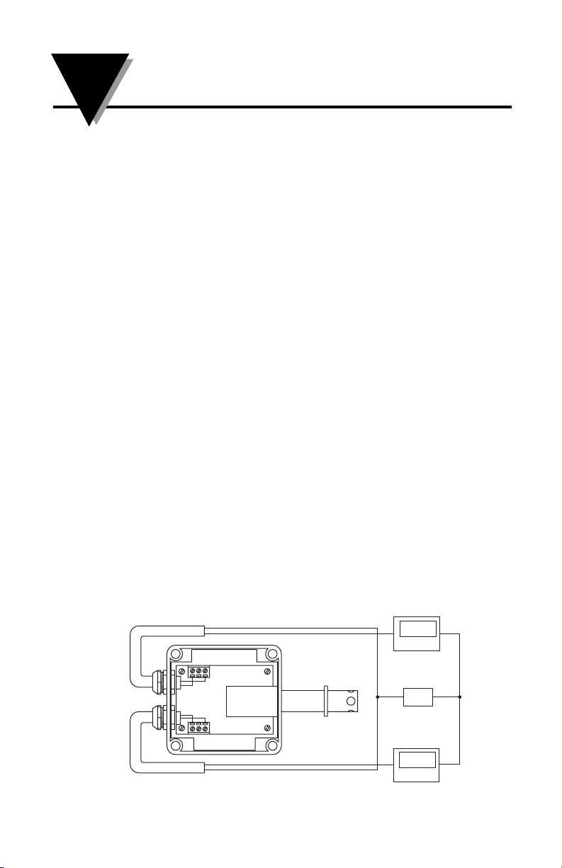
Figure 1 - Basic Transmitter Set-up With Current Loop Output
3
HX93A, HX93DA SERIES
RH/Temperature Transmitter
continued from page 1
23°C
–
+
TB2
TB1
DPi8 Panel Meter
–
+
24V
PSU-93
+
45%RH
DPi8 Panel Meter
–
Page 7

3
Complimentary Instruments
Power Supply, OMEGA®Part No.: PSU-93
Csi32 Series Panel Meters and Controllers
Recommended Accessories
Shielded Transmitter Cable, OMEGA
®
Part No.: TX4-100 (100 ft)
RH Calibration Kit, OMEGA
®
Part No.: HX92-CAL
4. Mounting
OMEGA’s HX93A and HX93DA transmitter’s are designed for either
wall, duct or remote probe mounting depending upon model. Plastic
wall anchors and mounting screws are included for wall mounting and
remote probe models. A duct mounting kit is included with duct
mount models.
Figure 2 - Wall Mount Model Dimensions, mm (inches)
Figure 3 - Duct Mount & Remote Probe Model Dimensions, mm (inches)
4
HX93A, HX93DA SERIES
RH/Temperature Transmitter
4.3 (.17)
MOUNTING
HOLE
63.5 (2.15)
95.3 (3.25)
DIMENSIONS mm (in.)
69.9
ø15.8(ø.625)
49.8 (1.96)
79.8 (3.14)
4.3 (.17)
95.3 (3.25)
DIMENSIONS mm (in.)
69.9 (2.75)
MOUNTING
HOLE
79. (3.14)
49.8 (1.96)
55 (2.17)
16 (.62) DIA
127 (5.0)
Page 8

4
5. Electrical Connections
All electrical connections and wiring should be performed by a suitably
trained professional only.
Models: HX93AC, HX93AC-D, HX93AC-RP1, HX93DAC, HX93DACD,HX93DAC-RPI (Current Output)
TB1 - Relative Humidity TB2 - Temperature
1. + Power Supply 1. + Power Supply
2. No Connection 2. No Connection
3. 4-20 mA Output 3. 4-20 mA Output
6. Current Transmitter Wiring Examples
For current output models (4 – 20 mA)
Figure 4 - Current Transmitter Wiring Example, (4 - 20 mA)
All electrical connections and wiring should be performed by a suitably
trained professional only.
CAUTION
CAUTION
5
HX93A, HX93DA SERIES
RH/Temperature Transmitter
TEMPERATURE OUTPUT
TB2
21
3
23°C
24V
PSU-93
45%RH
–
–
–
1
2
3
TB1
RELATIVE HUMIDITY OUTPUT
+
DPi8 Panel Meter
+
+
DPi8 Panel Meter
Page 9

5
Models: HX93AV, HX93AV-D HX93AV-RP1 (Voltage Output)
TB1 - Relative Humidity TB2 - Temperature
1. + Power Supply 1. + Power Supply
2. + Output 2. + Output
3. - Power Supply 3. - Power Supply
7. Voltage Transmitter Wiring Examples
For voltage output models (0 to 1 Vdc)
Figure 5 - Voltage Transmitter Wiring Example
8. Relative Humidity Output Calculations
To calculate % Relative Humidity by measuring the current or voltage
output use the following formulas.
For current output:
% RH = (Current measured in miliamps – 4) ÷ .16
EXAMPLE: (11.04 mA – 4) ÷ .16 = 44% RH
For voltage output:
% RH = (Voltage measured in volts x 100)
EXAMPLE: .44 x 100 = 44% RH
7
HX93A, HX93DA SERIES
RH/Temperature Transmitter
TEMPERATURE OUTPUT
TB2
2
13
+
–
24V
PSU-93
1
2
3
TB1
RELATIVE HUMIDITY OUTPUT
+
23°C
DPi8 Panel Meter
+
45%RH
DPi8 Panel Meter
–
–
Page 10

6
9. RH Measured Vs Output Reading
10. Temperature Output Calculations
To calculate Temperature by measuring the current or voltage output
use the following formulas.
For Current output in ºC (-20 to 75ºC)
ºC = (Output measured in miliamps – 4) ÷ .1684 - 20 = ºC
EXAMPLE: (12.0 mA – 4) ÷ .1684 - 20 = 27.5ºC
For Current output ºF (-4 to 167ºF)
ºF = (Output measured in miliamps – 4) ÷ .0935 - 4 = ºF
EXAMPLE: (12.0 mA – 4) ÷ .0935 - 4 = 81.6ºF
For Voltage output in ºC (-20 to 75ºC)
ºC = (Output measured in volts ÷ .010526) - 20 = ºC
EXAMPLE: (0.50 Vdc ÷ .010526) - 20 = 27.5ºC
For Voltage output ºF (-4 to 167ºF)
ºF = (Output measured in volts ÷ .005848) - 4 = ºF
EXAMPLE: (0.50 Vdc ÷ .005848) - 4 = 81.5ºF
% Relative
Output
Humidity Current (mA) Voltage (Vdc)
5 4 0.8 .05
10 5.6 .10
15 6.4 .15
20 7.2 .20
25 8.0 .25
30 8.8 .30
35 9.6 .35
40 10.4 .40
45 11.2 .45
50 12.0 .50
55 12.8 .55
60 13.6 .60
65 14.4 .65
70 15.2 .70
75 16.0 .75
80 16.8 .80
85 17.6 .85
90 18.4 .90
95 19.2 .95
9
HX93A, HX93DA SERIES
RH/Temperature Transmitter
Page 11

7
11. Calibration
Your transmitter has been factory calibrated to meet or exceed the
specifications outlined in this manual. To maintain original
specifications it is generally recommended that your transmitter be recalibrated on an annual basis depending on operating conditions.
12. Calibration Procedure for HX93AC (all styles)
Relative Humidity Adjustment
Recommended equipment:
• Humidity Calibration Kit, OMEGA®Model No.: HX92-CAL
• Handheld Digital Multi-meter, OMEGA
®
Model No.: HHM29
• Dc Power Supply, OMEGA
®
Model No.: PSU-93
1. Remove enclosure cover
2. Connect transmitter as shown in figure below.
3. Apply power to transmitter and allow to warm up for 15 min.
4. Place unit in a 11% RH environment and allow to stabilize for 15 min.
5. Adjust potentiometer “P1” for a output reading of 5.76 mA
6. Place unit in a 75% RH environment and allow to stabilize for 15 min.
7. Adjust potentiometer “P2” for a output reading of 16.0 mA
8. Repeat steps 4, 5, 6, and 7 as necessary until proper readings are maintained.
9. Calibration complete.
Figure 6 - HX93AC Calibration Procedure
Relative Humidity Adjustment
11
HX93A, HX93DA SERIES
RH/Temperature Transmitter
NOTE:
Do not adjust
P3. This is a
factory
setting.
SENSOR HEAD
+
16.00 mA
10A
24V
PSU-93
HHM29
uAmA
COM
–
TB1
123
123
TB2
P3
P1
P2
HX92-CA
CALIBRATION BOTTLE
V
Page 12

8
13. Calibration Procedure for HX93AC (all styles)
Temperature Adjustment
Recommended equipment:
• RTD Simulator OMEGA®Model No.: CL510-1
• Handheld Digital Multi-meter, OMEGA
®
Model No.: HHM29
• Dc Power Supply, OMEGA
®
Model No.: PSU-93
1. Remove enclosure cover
2. Connect the power supply and multimeter as shown in the figure
below.
3. Disconnect the 2-wire Connector “J4” from the main Board.
4. Connect the RTD simulator to the “J4” header on the main board as
shown below.
5. Apply power to transmitter and allow to warm up for 10 min.
6. Set the RTD simulator to the 0ºF position.
7. Adjust potentiometer “P5” on the main board for a output reading
of 4.43 mA @ 0°F
8. Set the RTD simulator to the 150ºF position.
9. Adjust potentiometer “P4” for a output reading of 18.46 mA 150°F
10. Repeat steps 6, 7, 8 and 9 as necessary until proper readings are
maintained.
11. Calibration complete.
Figure 7 - HX93AC Calibration Procedure
Temperature Adjustment
13
HX93A, HX93DA SERIES
RH/Temperature Transmitter
+
PSU-93
10A
24V
HHM29
18.41 mA
COM
uAmA
–
V
CL-301
SENSOR HEAD
TB1
1
3
2
2
3
1
TB2
P5
P4
J4
Page 13

9
14. Calibration Procedure for HX93AV (all styles)
Relative Humidity Adjustment
Recommended equipment:
• Humidity Calibration Kit, OMEGA®Model No.: HX92-CAL
• Handheld Digital Multi-meter, OMEGA
®
Model No.: HHM29B
• Dc Power Supply, OMEGA
®
Model No.: PSU-93
1. Remove enclosure cover.
2. Connect transmitter as shown in figure below.
3. Apply power to transmitter and allow to warm up for 15 min.
4. Place unit in a 11% RH environment and allow to stabilize for 15 min.
5. Adjust potentiometer “P3” for a output reading of .110 Vdc.
6. Place unit in a 75% RH environment and allow to stabilize for 15 min.
7. Adjust potentiometer “P2” for a output reading of .750 Vdc.
8. Repeat steps 4, 5, 6, and 7 as necessary until proper readings are
maintained.
9. Calibration complete.
Figure 8 - HX93AV Calibration Procedure
Relative Humidity Adjustment
HHM29
SENSOR HEAD
HX92-CA
CALIBRATION BOTTLE
PSU-93
24V
.750 V
P3
TB1
P1
TB2
P2
+–
uAmA10A
COM
V
132
321
14
HX93A, HX93DA SERIES
RH/Temperature Transmitter
Page 14

10
15. Calibration Procedure for HX93AV (all Styles)
Temperature Adjustment
Recommended equipment:
• 100 Ohm RTD Simulator OMEGA®Model No.: CL510-1
• Handheld Digital Multi-meter, OMEGA
®
Model No.: HHM29
• Dc Power Supply, OMEGA
®
Model No.: PSU-93
1. Remove enclosure cover
2. Connect the power supply and multimeter as shown in the figure
below.
3. Disconnect the 2-wire Connector “J4” from the main Board.
4. Connect the RTD simulator to the “J4” header on the main board as
shown below.
5. Apply power to transmitter and allow to warm up for 10 min.
6. Set the RTD simulator to the 0ºF position.
7. Adjust potentiometer “P5” on the main board for a output reading
of 0.023 Vdc
8. Set the RTD simulator to the 150ºF position.
9. Adjust potentiometer “P4” for a output reading of 0.901 Vdc
10. Repeat steps 6, 7, 8 and 9 as necessary until proper readings are
maintained.
11. Calibration complete.
Figure 9 - HX93AV Calibration Procedure
Temperature Adjustment
15
HX93A, HX93DA SERIES
RH/Temperature Transmitter
CL-301
321
132
TB1
SENSOR HEAD
TB2
P5
P4
J4
+
HHM29
10A
uAmA V
24V
PSU-93
.901 V
COM
–
Page 15

11
15A. Display Scaling for HX93DAC (all styles)
Your HX93DA transmitter comes with dual built-in LCD indicators for
displaying both Humidity and Temperature. Before the meter
adjustment or re-scaling can be done the transmitters current output
should be checked as per the calibration procedure in Section 12 and 13
to verify the display will be adjusted correctly and match the analog
output.
Relative Humidity Display Scaling
Recommended equipment:
• Humidity Calibration Kit, OMEGA®Model No.: HX92-CAL
• Handheld Digital Multi-meter, OMEGA
®
Model No.: HHM29
• Dc Power Supply, OMEGA
®
Model No.: PSU-93
1. Remove enclosure cover
2. Connect transmitter as shown in figure 6.
3. Apply power to transmitter and allow to warm up for 15 min.
4. Place unit in a 11% RH environment and allow to stabilize for 15 min.
5. Adjust potentiometer "ZERO" on the back of the RH display for a
reading of 11.0%
6. Place unit in a 75% RH environment and allow to stabilize for 15 min.
7. Adjust potentiometer "GAIN" on the back of the RH display for a
reading of 75.0%
8. Repeat steps 4, 5, 6, and 7 as necessary until proper readings are
maintained.
9. Re-scaling complete.
Figure 10 - Transmitter Lid Rear View
15A
HX93A, HX93DA SERIES
RH/Temperature Transmitter
ZERO POTENTIOMETER
GAIN POTENTIOMETER
ZERO POTENTIOMETER
GAIN POTENTIOMETER
TRANSMITTER LID REAR VIEW
Z
G
–
+
Z
G
–
+
RELATIVE HUMIDITY
INDICATOR
TEMPERATURE
INDICATOR
Page 16

HX93A, HX93DA SERIES
RH/Temperature Transmitter
15A
12
Temperature Display Scaling
Recommended equipment:
• RTD Simulator OMEGA®Model No.: CL510-1
• Handheld Digital Multi-meter, OMEGA
®
Model No.: HHM29
• Dc Power Supply, OMEGA
®
Model No.: PSU-93
For ºF Display
1. Remove enclosure cover
2. Connect the power supply and multimeter as shown in the figure 7.
3. Disconnect the 2-wire Connector "J4" from the main Board.
4. Connect the RTD simulator to the "J4" header on the main board as
shown below.
5. Apply power to transmitter and allow to warm up for 10 min.
6. Set the RTD simulator for 0ºF output. (See figure on page 11.)
7. Adjust potentiometer "ZERO" on the back of the Temp display for a
reading of 0.0ºF
8. Set the RTD simulator for 150ºF output.
9. Adjust potentiometer "GAIN" on the back of the RH display for a
reading of 150.0ºF
10. Repeat steps 6, 7, 8 and 9 as necessary until proper readings are
maintained.
11. Calibration complete.
For ºC Display
12. Remove enclosure cover
13. Connect the power supply and multimeter as shown in the figure 7.
14. Disconnect the 2-wire Connector "J4" from the main Board.
15. Connect the RTD simulator to the "J4" header on the main board as
shown below.
16. Apply power to transmitter and allow to warm up for 10 min.
17. Set the RTD simulator for 0ºC output. (See figure on page 11.)
18. Adjust potentiometer "ZERO" on the back of the Temp display for a
reading of 0.0ºC
19. Set the RTD simulator to the 150ºC output.
20. Adjust potentiometer "GAIN" on the back of the RH display for a
reading of 150.0ºF
21. Repeat steps 6, 7, 8 and 9 as necessary until proper readings are
maintained.
Calibration complete.
Page 17

13
16. Maintenance
If your Humidity transmitter will be used in a dusty environment, the
protective sensor filter, if clogged, may be removed for cleaning.
Unscrew the protective cover and gently blow compressed air through
the filter screen. A soft brush may also be used to remove dirt particles
from the screen.
If the sensor is subjected to 100% condensation, it must be dried to
obtain correct readings. There will be no permanent damage or
calibration shift to the unit.
Units should not be exposed to high concentrations of ammonia or
alcohol vapors.
17. Specifications
Relative Humidity
Measuring Range: 3 - 95% (non-condensing)
Accuracy: ±2.5% @ 72ºF with an added temperature
coefficient error of -.06% RH/ºF (both
increasing and decreasing in temperature).
Repeatability: ± 1 % RH
Operating
Temperature Range: -20 to 75ºC (-4 to 167ºF)
Output:
Model: HX93AC 4 to 20 mA (Scaled for 0 to 100% RH)
Model : HX93AV 0 to 1 Vdc (Scaled for 0 to 100% RH)
Power: 6 –30 Vdc @ 20mA
Max Loop Resistance: Ohms = (V supply – 6 V)/.02 A
RH Time Constant (90%
response at 25ºC, in
moving air at 1m/s): >10 seconds, 10 to 90% RH
>15 seconds, 90 to 10% RH
Sensor Type: Thin Film Polymer Capacitor
Temperature
Measuring Range: -20 to 75ºC (-4 to 167ºF)
Accuracy: ± 0.6ºC (1ºF)
Repeatability: ± 0.3ºC (0.5ºF)
Output:
Model: HX93AC 4 to 20 mA (Scaled for 0 to 100% RH)
Model : HX93AV 0 to 1 Vdc (Scaled for 0 to 100% RH)
Power:
No Displays 6 -30 Vdc @ 20mA
With Displays 12 - 30 Vdc @ 30mA
16
HX93A, HX93DA SERIES
RH/Temperature Transmitter
Page 18

14
Max Loop Resistance: Ohms = (V supply – 6 V)/.02 A
Sensor Type: 100 Ohm Platinum RT
18. General Specifications
Enclosure Housing: Gray Polycarbonate, (IP 65, DIN 40050)
NEMA rated up to 13, UL Listed.
Connections
Cable Strain Relief: Nylon, Liquid-tight with neoprene gland for
2.29 to 6.73 mm (.09 to .265") diameter cable.
Wire Connections: Internal 3-Position Terminal Strip. Accepts
from 14 to 22 gage wire.
Dimensions: See “Mounting” Section
Weight
Wall Mount Model: 82 g. (3 oz)
Duct Mount Model: 100 g. (3.5 oz)
18
HX93A, HX93DA SERIES
RH/Temperature Transmitter
Page 19

WARRANTY/ DISCLAIMER
OMEGA ENGINEERING, INC. warrants this unit to be free of defects in materials and
workmanship for a period of 13 months from date of purchase. OMEGA’s Warranty adds an
additional one (1) month grace period to the normal one (1) year product warranty to cover
handling and shipping time. This ensures that OMEGA’s customers receive maximum
coverage on each product.
If the unit malfunctions, it must be returned to the factory for evaluation. OMEGA’s Customer
Service Department will issue an Authorized Return (AR) number immediately upon phone or
written request. Upon examination by OMEGA, if the unit is found to be defective, it will be
repaired or replaced at no charge. OMEGA’s WARRANTY does not apply to defects resulting
from any action of the purchaser, including but not limited to mishandling, improper interfacing,
operation outside of design limits, improper repair, or unauthorized modification. This
WARRANTY is VOID if the unit shows evidence of having been tampered with or shows evidence
of having been damaged as a result of excessive corrosion; or current, heat, moisture or vibration; improper specification; misapplication; misuse or other operating conditions outside of
OMEGA’s control. Components which wear are not warranted, including but not limited to
contact points, fuses, and triacs.
OMEGA is pleased to offer suggestions on the use of its various products. However,
OMEGA neither assumes responsibility for any omissions or errors nor assumes liability
for any damages that result from the use of its products in accordance with information
provided by OMEGA, either verbal or written. OMEGA warrants only that the parts
manufactured by it will be as specified and free of defects. OMEGA MAKES NO OTHER
WARRANTIES OR REPRESENTATIONS OF ANY KIND WHATSOEVER, EXPRESS OR
IMPLIED, EXCEPT THAT OF TITLE, AND ALL IMPLIED WARRANTIES INCLUDING ANY
WARRANTY OF MERCHANTABILITY AND FITNESS FOR A PARTICULAR PURPOSE ARE
HEREBY DISCLAIMED. LIMITATION OF LIABILITY: The remedies of purchaser set forth
herein are exclusive, and the total liability of OMEGA with respect to this order, whether
based on contract, warranty, negligence, indemnification, strict liability or otherwise, shall
not exceed the purchase price of the component upon which liability is based. In no event
shall OMEGA be liable for consequential, incidental or special damages.
CONDITIONS: Equipment sold by OMEGA is not intended to be used, nor shall it be used: (1) as
a “Basic Component” under 10 CFR 21 (NRC), used in or with any nuclear installation or activity;
or (2) in medical applications or used on humans. Should any Product(s) be used in or with any
nuclear installation or activity, medical application, used on humans, or misused in any way,
OMEGA assumes no responsibility as set forth in our basic WARRANTY/ DISCLAIMER language,
and, additionally, purchaser will indemnify OMEGA and hold OMEGA harmless from any liability
or damage whatsoever arising out of the use of the Product(s) in such a manner.
RETURN REQUESTS/INQUIRIES
Direct all warranty and repair requests/inquiries to the OMEGA Customer Service Department.
BEFORE RETURNING ANY PRODUCT(S) TO OMEGA, PURCHASER MUST OBTAIN AN
AUTHORIZED RETURN (AR) NUMBER FROM OMEGA’S CUSTOMER SERVICE DEPARTMENT
(IN ORDER TO AVOID PROCESSING DELAYS). The assigned AR number should then be
marked on the outside of the return package and on any correspondence.
The purchaser is responsible for shipping charges, freight, insurance and proper packaging to
prevent breakage in transit.
FOR WARRANTY
RETURNS, please have
the following information available BEFORE
contacting OMEGA:
1. Purchase Order number under which
the product was PURCHASED,
2. Model and serial number of the product
under warranty, and
3. Repair instructions and/or specific
problems relative to the product.
FOR NON-WARRANTY REPAIRS,
consult
OMEGA for current repair charges. Have the
following information available BEFORE
contacting OMEGA:
1. Purchase Order number to cover the
COST of the repair,
2. Model and serial number of the
product, and
3. Repair instructions and/or specific problems
relative to the product.
OMEGA’s policy is to make running changes, not model changes, whenever an improvement is possible.
This affords our customers the latest in technology and engineering.
OMEGA is a registered trademark of OMEGA ENGINEERING, INC.
© Copyright 2003 OMEGA ENGINEERING, INC. All rights reserved. This document may not be copied, photocopied,
reproduced, translated, or reduced to any electronic medium or machine-readable form, in whole or in part, without
the prior written consent of OMEGA ENGINEERING, INC.
Page 20

Where Do I Find Everything I Need for
Process Measurement and Control?
OMEGA…Of Course!
Shop online at www.omega.com
TEMPERATURE
Thermocouple, RTD & Thermistor Probes, Connectors, Panels & Assemblies
Wire: Thermocouple, RTD & Thermistor
Calibrators & Ice Point References
Recorders, Controllers & Process Monitors
Infrared Pyrometers
PRESSURE, STRAIN AND FORCE
Transducers & Strain Gages
Load Cells & Pressure Gages
Displacement Transducers
Instrumentation & Accessories
FLOW/LEVEL
Rotameters, Gas Mass Flowmeters & Flow Computers
Air Velocity Indicators
Turbine/Paddlewheel Systems
Totalizers & Batch Controllers
pH/CONDUCTIVITY
pH Electrodes, Testers & Accessories
Benchtop/Laboratory Meters
Controllers, Calibrators, Simulators & Pumps
Industrial pH & Conductivity Equipment
DATA ACQUISITION
Data Acquisition & Engineering Software
Communications-Based Acquisition Systems
Plug-in Cards for Apple, IBM & Compatibles
Datalogging Systems
Recorders, Printers & Plotters
HEATERS
Heating Cable
Cartridge & Strip Heaters
Immersion & Band Heaters
Flexible Heaters
Laboratory Heaters
ENVIRONMENTAL
MONITORING AND CONTROL
Metering & Control Instrumentation
Refractometers
Pumps & Tubing
Air, Soil & Water Monitors
Industrial Water & Wastewater Treatment
pH, Conductivity & Dissolved Oxygen Instruments
M0933A/0703
 Loading...