

Page 1
User’s Guide
Shop online at
omega.com
e-mail: [email protected]
®
For latest product manuals:
omegamanual.info
MADE IN TAIWAN
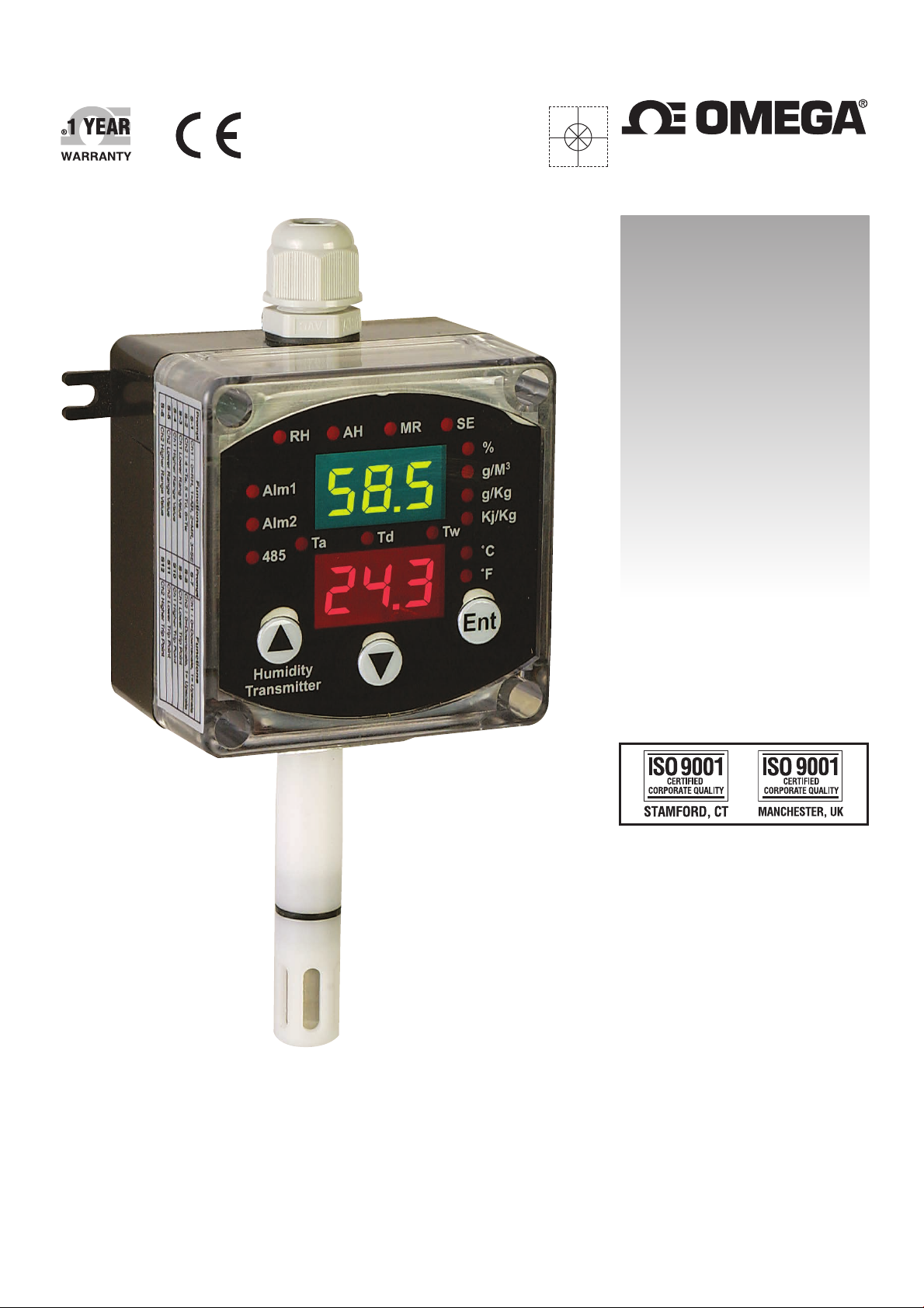
HX400 SERIES
Humidity/Temperature
Transmitter
Page 2

OMEGAnet®Online Service Internet e-mail
omega.com [email protected]
Servicing North America:
U.S.A.: Omega Engineering, Inc., One Omega Drive, P.O. Box 4047
ISO 9001 Certified Stamford, CT 06907-0047 USA
Canada: 976 Bergar
Laval (Quebec), H7L 5A1 Canada
Toll-Free: 1-800-826-6342 TEL: (514) 856-6928
FAX: (514) 856-6886 e-mail: [email protected]
For immediate technical or application assistance:
U.S.A. and Canada: Sales Service: 1-800-826-6342/1-800-TC-OMEGA
Customer Service: 1-800-622-2378/1-800-622-BEST
Engineering Service: 1-800-872-9436/1-800-USA-WHEN
Mexico/ En Español: 001 (203) 359-7803 FAX: 001 (203) 359-7807
Latin America [email protected] e-mail: [email protected]
®
®
®
Servicing Europe:
Benelux: Managed by the United Kingdom Office
Czech Republic: Frystatska 184
733 01 Karviná, Czech Republic
Toll-Free: 0800-1-66342 TEL: +420-59-6311899
FAX: +420-59-6311114 e-mail: [email protected]
France: Managed by the United Kingdom Office
Toll-Free: 0800 466 342 TEL: +33 (0) 161 37 29 00
FAX: +33 (0) 130 57 54 27 e-mail: [email protected]
Germany/ Austria: Daimlerstrasse 26
D-75392 Deckenpfronn, Germany
Toll-Free: 0800 6397678 TEL: +49 (0) 7056 9398-0
FAX: +49 (0) 7056 9398-29 e-mail: [email protected]
United Kingdom: OMEGA Engineering Ltd.
ISO 9001 Certified One Omega Drive, River Bend Technology Centre, Northbank
Irlam, Manchester M44 5BD United Kingdom
Toll-Free: 0800-488-488 TEL: +44 (0) 161 777-6611
FAX: +44 (0) 161 777-6622 e-mail: [email protected]
It is the policy of OMEGA Engineering, Inc. to comply with all worldwide safety and EMC/EMI
regulations that apply. OMEGA is constantly pursuing certification of its products to the European New
Approach Directives. OMEGA will add the CE mark to every appropriate device upon certification.
The information contained in this document is believed to be correct, but OMEGA accepts no liability for any
errors it contains, and reserves the right to alter specifications without notice.
WARNING: These products are not designed for use in, and should not be used for, human applications.
Page 3

CONTENTS
1 Introduction
2. Electrical Installation
3. Configuration
3.1 Measuring Mode
3.2 Entering the Setup Mode
3.2.1 Select Ch #1 Parameters Output
3.2.2 Select Ch #2 Parameters Output
3.2.3 Set Ch #1 ZERO value
3.2.4 Set Ch #1 SPAN value
3.2.5 Set Ch #2 ZERO value
3.2.6 Set Ch #2 SPAN value
3.2.7 Set Ch #1 Upscale/ Downscale output
3.2.8 Set Ch #2 Upscale/ Downscale output
3.2.9 Set Ch #1 Lower Trip Point value
3.2.10 Set Ch #1HigherTrip Point value
3.2.11 Set Ch #2 Lower Trip Point value
3.2.12 Set Ch #2 Higher Trip Point value
3.2.13 Set Ch #1 & Ch #2 Hysteresis value
3.2.14 Set the Ch #1 Alarm Mode
3.2.15 Set the Ch #2 Alarm Mode
3.2.16 Set Temperature Units
3.2.17 Set Local Barometric Pressure
3.2.18 Set Ch #1 or Ch #2
4. Calibration
4.1 Calibration Equipment
4.2 Entering the Calibration Mode
4.2.1 Trim Ch #1 Loop Current 4.00 mA
4.2.2 Trim Ch #1 Loop Current 20.00 mA
4.2.3 Trim Ch #2 Loop Current 4.00 mA
4.2.4 Trim Ch #2 Loop Current 20.00 mA
4.2.5 Adjustment one-point Humidity
4.2.6 Adjustment one-point Temperature
4.2.7 Calibration 11.3 %RH Humidity
4.2.8 Calibration 57.5 %RH Humidity
4.2.9 Calibration 84.3 %RH Humidity
5. Maintenance
5.1 Sensor replaced
6. Error Code
7. Model description
2
Page 4
1. Introduction
This manual contains information for the installation and operation of the HX400 Series
Humidity/Temperature Transmitter. The HX400 Series 2-wire loop-powered programmable
multi-units transmitter, is a versatile instrument which Converts, Indicates, Transmits and
Switches the input signal from an integrated digital polymer capacitive humidity sensor and a
PN barrier silicon temperature sensor into a linearized, temperature compensated, dual
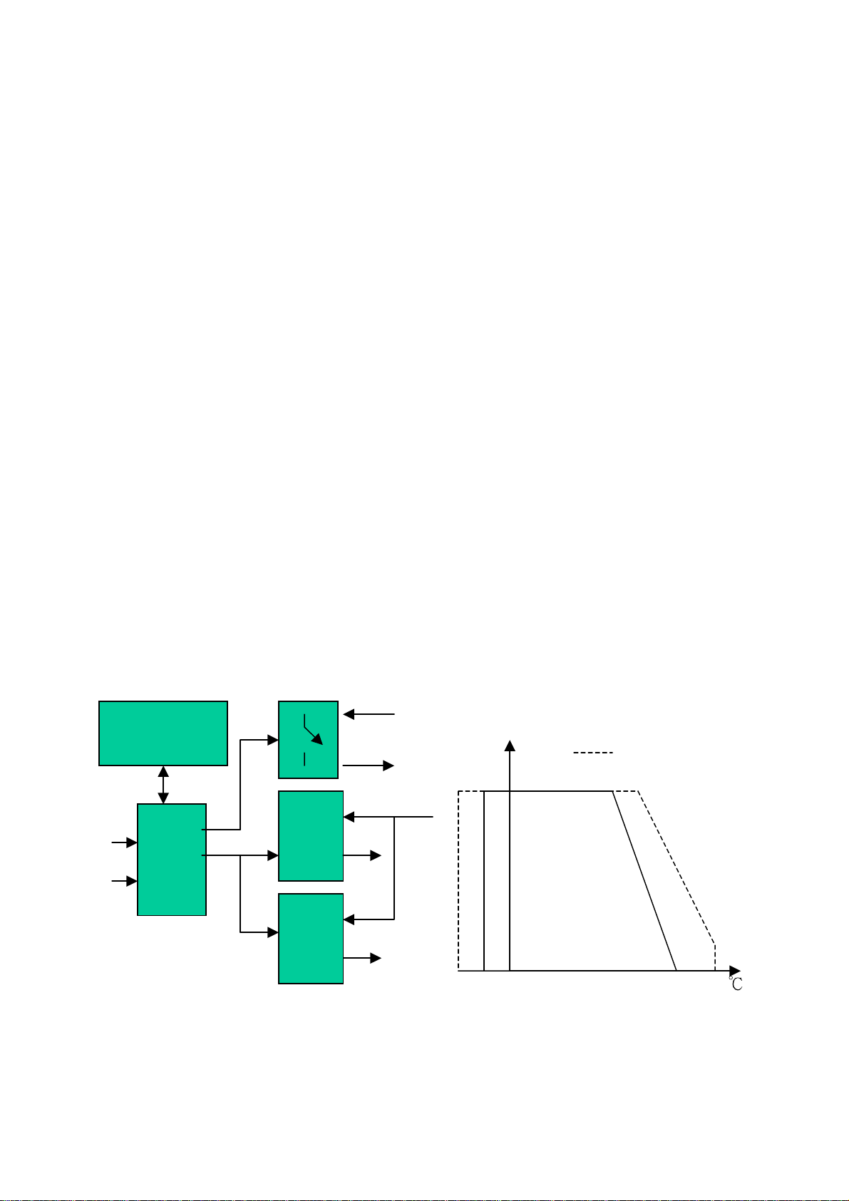
single analog 4 - 20m ADC loop current output. See the unit block diagram <Fig. 1>
The HX400 Series is microprocessor based incorporating advanced electronic circuitry that
enables it to provide a high degree of performance and flexibility yet at a reasonable cost
and ease of use. The HX400 Series consists of a 3 push button front keyboard with dual color
3-digit 7-segments high bright LED modules. The display modules are used to indicate the
values of the measured parameters and computed values during Measuring Mode, and
provide prompting and programming instructions during Setup Mode and Calibration Mode.
See sensor operating condition <Fig 1-a>
The Setup Mode may be used by the user who wishes to re-configure the transmitter for
new applications. The Calibration Mode may be used by the user who wishes to maintain the
high performance of the unit. All of
EEPROM. If power to the transmitter is lost, the unit resumes normal operation with the
parameters that have been configured upon reapplication power. The Transmitter’s dual
independent analog output range can be set anywhere within the operating range.
The HX400 Series provides dual galvanic isolated solid state single pole relay output which
could be programmed as a high, low or window trips each with normally open or close
contacts for a variety of control applications.
Switch
Output RH% Max. Operating
100 Conditions
Humidity Loop Power
Sensor
Normal
Temp. Operating
Sensor
20
Push buttons
8 8 8
MCU
the working parameters and calibration data are saved on
Ch#1
V/I
Ch#2
V/I
-40 20 0 60 80 100 120
<Fig1> Block Diagram for HX402 Model <Fig 1-a> Sensor Operating Conditions
Ch #1 equipped only for HX401 Model
3
Page 5
2. Electrical Wired & Installation
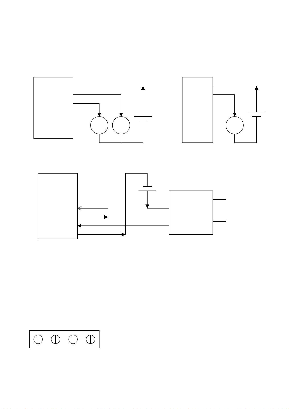
The power cord is one-meter length, 22 AWG, 7/6 different colors for recognition. Please
pay attention to polarity (Wire Colored) when connecting loop power source and external
Solid State Relay device. Warning: Model HX402 will be damaged if only Ch #1 is
powered
+Vloop (Red) +Vloop (Red)
-Vloop1 (Black; Ch #1 ) -Vloop1 (Black)
-Vloop2 (Brown; Ch #2) Power Supply
12 ~ 30 Vdc PS
mA mA mA
<Fig. 2a> HX402 power connection <Fig. 2b> HX401 power connection
External
HX401 10 ~ 24 Vdc
HX402
SW2+ (Blue) External SSR
SW2- (White) Power Relay AC load
SW1+ (Orange)
SW1- (Green)
<Fig.3> SW #1 & #2 Output Connection Diagram;
The built-in dual solid-state single pole switch output stress capacity is 40Vdc max. 15 mA
max. between terminal SW+ and terminal SW-
The Transmitter is designed for use in non-aggressive environments and indoor room use.
It is not recommended to use under condensation and water aerosol conditions. This use
could cause of water steam condensation on the sensor surface. If these conditions occur
it can cause sensor damage or dramatically increase response time for humidity change. .
#1 #2 #3 #4 Wire colored
#1: Green (Gn)
#2: Red (Rd)
<Fig 4 > Probe Connection #3: Brown (Bn)
#4: Black (Bk)
Connection Port on PCB location
4
Page 6
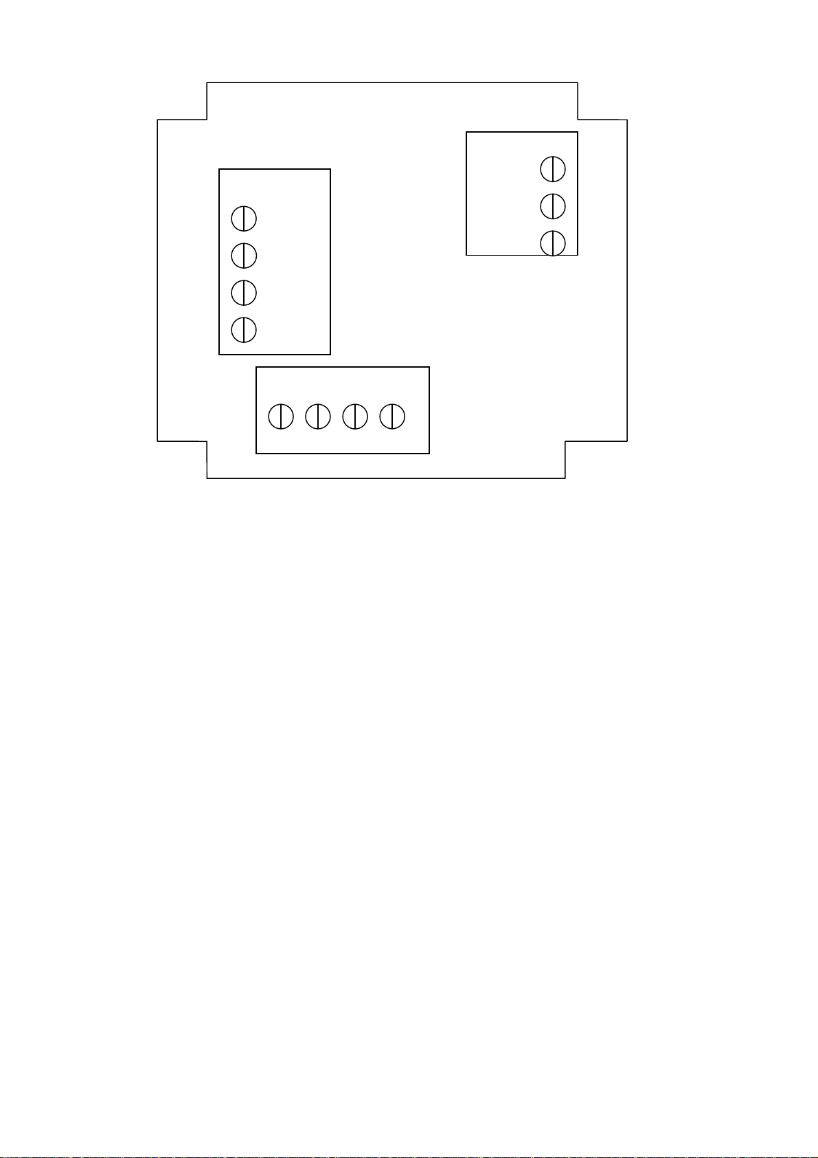
Power Port
SW. Port
+Vloop
-Vloop1
SW2+
-Vloop2
SW2 SW1+
SW1-
Probe Port
Gn Rd Bn Bk
<Fig 5> Internal Wire Connection
5
Page 7

3. Configuring the HX400
The HX400 may be supplied factory configured for the working parameters as specified by the
customer at time of order. Use this manual in order to alter and modify the existing parameters
for new applications.
Keyboard Description:
ENT: ENTER key: Choose current display function or value as the correct and valid one. Also to
be used to enter into one of the programming states.
: UP key: Use to increase the numerical value of the display. Also to be used to scroll upwards
through the program menu during Measuring, Setup and Calibration Mode.
: DOWN key: Use to decrease the numerical value of the display. Also to be used to scroll
downwards through the program menu during Measuring, Setup and Calibration
Mode.
<Note>: Please do not press and release fast during operation the key, recommend at least
holding up 0.5 Sec when pressed.
The HX400 Setup and Calibration functions are configured through a two level of access push
button sequence. In order to use, the menu is divided into three main categories: Measuring,
Setup and Calibrate Mode. The HX400 enters Measuring Mode automatically after power on.
3.1 Measuring Mode
The Measuring Mode is the normal operating mode after power on. In Measuring Mode, using all
of the working parameters which were setup in Setup Mode, the outputs dual loop current
displays the measured values on the dual high bright 7-Segments LED modules, the meter will
do temperature drift compensation and real-time self-diagnostic checks. The sensor input circuit
is monitored for failure and the output current responds in a defined value
The HX400 is equipped with dual 4 ~ 20 mA current outputs and display modules, Channel #1
could be configured for Relative Humidity (RH), Absolutely Humidity (AH), Mixing Ratio (MR) or
Specific Enthalpy (SE) computed parameters displayed on upper display module (Green Color)
and Current Output, Channel #2 could be configured for Air Temperature (Ta), Dew Point
Temperature (Td)
or Wet Bulb Temperature (Tw) computed parameters displayed on lower
display module (Red Color) and Current Output. Two temperature engineering units Celsius,
Fahrenheit can be displayed with associated LED lamp in Ch # 2. Both Channels are
independent of operation. Also the meter can check Max/Min readings since powered on or the
last reset operation by press the ENTER key. When measured variable meets the alarm
conditions the built-in solid-state single pole relay will be energized or un-energized depending
on the Alarm Mode set and its associated LED lamp indication.
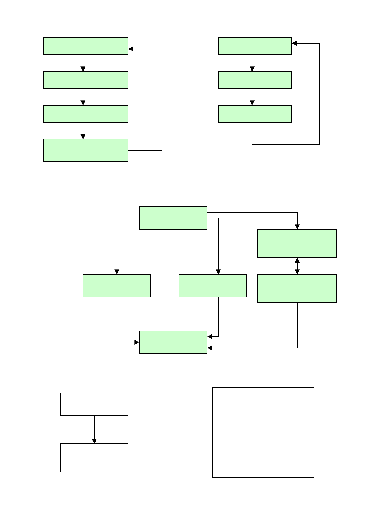
Note: Press UP/DOWN key browses computed parameters displayed only during the Measuring
Mode
6
Page 8
. Display RH value
Display Ta value
Press UP key Press DOWN key
Display AH value
Display Td value
Press UP key Press DOWN key
Display MR value
Display Tw value
Press UP key
UP key Press DOWN key
Display SE value
< Channel #1> < Channel #2 >
<Fig. 6> Change displayed computed parameter only during Measuring Mode
Press ENTER key over 2 Sec.
Measuring Mode
Press UP & DOWN Press UP & ENTER
both key over 2 Sec. both key over 2 Sec.
Display Ch #1, #2
Max. Values
Press UP
.
Setup Mode
Calibration Mode
Display Ch #1, #2
Min. Values
Press DOWN & ENTER Press DOWN & ENTER
2 key simultaneously 2 key simultaneously Press
DOWN & ENTER
2 key simultaneously
Measuring Mode
<Fig. 7> Flow chart of Operating Mode
Max/Min Mode
Press DOWN key
over 2 Sec
Clear Ch #1, #2
Max/Min Values
RH: Relative Humidity
AH: Absolutely Humidity
MR: Mixing Ratio
SE: Specific Enthalpy
Ta: Air T emperature
Td: Dew Point Temperature
Tw: Wet Bulb Temperature
< Fig. 8 > Reset Ch #1, #2 Max/Min values
7
Page 9

3.2 Entering the Setup Mode
To start the Setup Mode, first press and hold the UP key and DOWN key simultaneously until the
setting prompt is displayed during Measuring Mode see< Fig 7>. The Setup Mode will allow the
user to do the following:
Change Ch #1 & Ch #2 computed parameter for Transmitting and Alarm operation.
Change Ch #1 & Ch #2 the 4mA Lower Range Value.
Change Ch #1 & Ch #2 the 20mA Full Scale Value.
Change Ch #1 & Ch #2 the Sensor Fail Safe detection. (Upscale/Downscale output)
Change Ch #1 & Ch #2 Lower / Higher Trip Point Value.
Change Ch #1 & Ch #2 Dead Band (Hysteresis) of Trip Point Value
Change SW #1 & SW #2 Alarm Operation Mode
Change Temperature Engineering Units and Local Barometric Pressure offset
Change Ch #1 or Ch #2 Active Output
Each of these functions prompts are presented in sequence on the upper LED display module.
Use the UP key or DOWN key to scroll the Setup Mode menu. To perform the displayed function
press the ENTER key, the transmitter will response by displaying the existing status or working
parameter on the lower LED display module. Press the UP key or DOWN key to increase or
decrease the displayed value that you want to configure. Finally press ENTER key again to save
the edited parameter into Non-Volatile Memory and display the next function prompt. These are
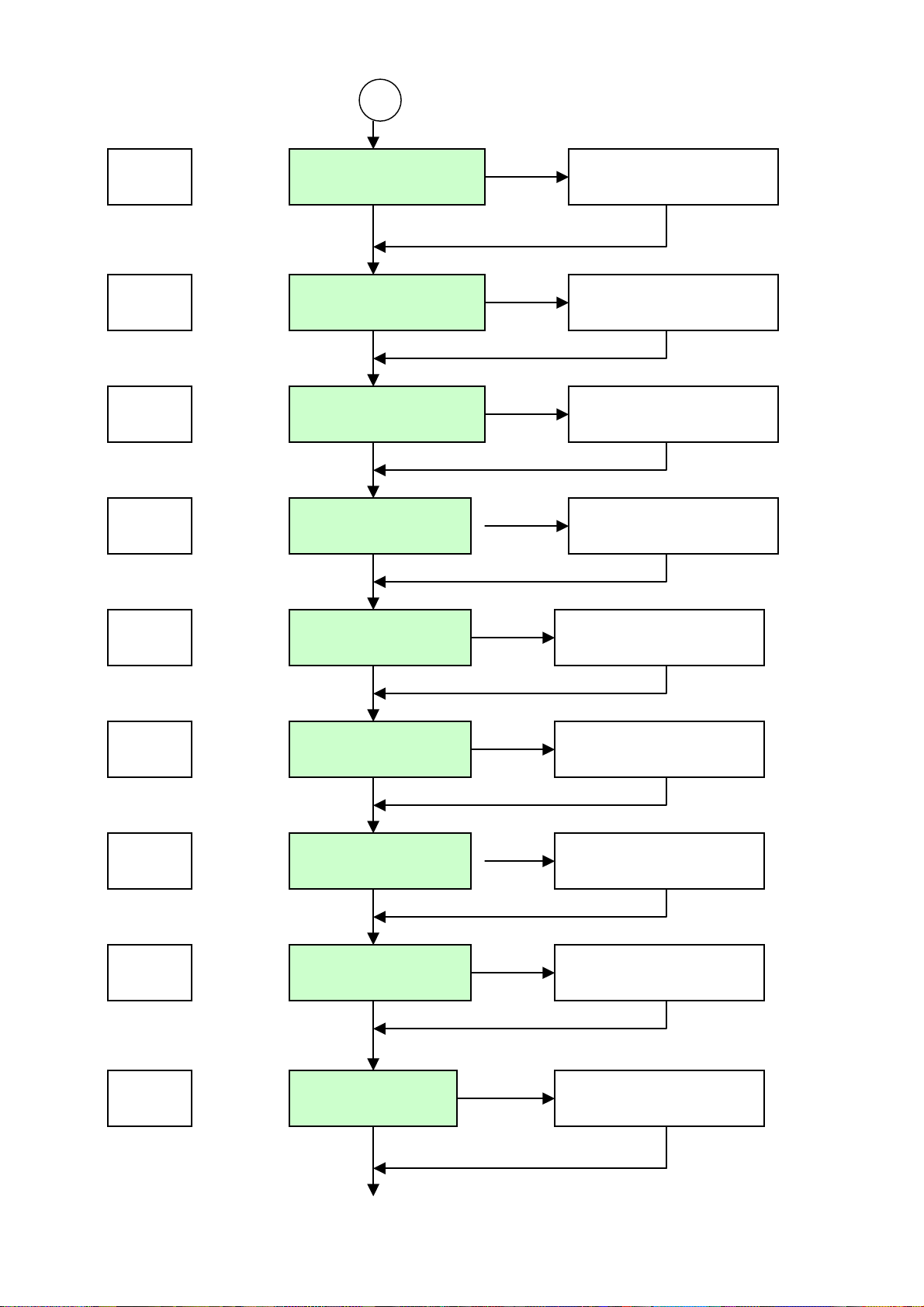
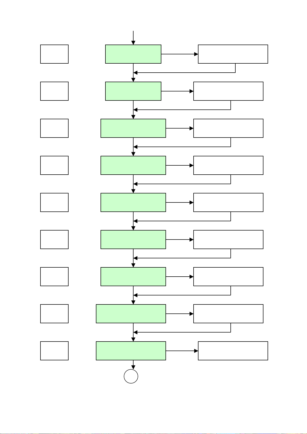
described in detail below and summarized on the Keyboard Flow Chart see< Fig. 9 >.
Displayed Prompt Functions ( Factory Set)
5-1
5-2
5-3
5-4
5-5
5-6
5-7
5-8
5-9
510
511
Set the Ch #1 computed parameter ( RH )
Set the Ch #2 computed parameter ( Ta )
Set the Ch #1 4mA Value (ZERO) ( 10 %RH)
Set the Ch #1 20mA Value (SPAN) ( 90 %RH)
Set the Ch #2 4mA Value (ZERO) (0 ℃)
Set the Ch #2 20mA Value (SPAN) (60 ℃)
Set the Ch #1 Upscale / Downscale output ( Downscale )
Set the Ch #2 Upscale / Downscale output (Downscale)
Set the Ch #1 Lower Trip Point Value ( 20 % RH)
Set the Ch #1 Higher Trip Point Value ( 60 % RH)
Set the Ch #2 Lower Trip Point Value ( 5 ℃)
512
513
514
515
516
517
Set the Ch #2 Higher Trip Point Value (50 ℃)
Set the Ch #1 & Ch #2 Dead Band of Trip Point (1% RH & 1℃ )
Set the Ch #1 Alarm Mode ( Disable )
Set the Ch #2 Alarm Mode ( Disable)
Set the Temperature Engineering Unit (℃ /℉ ) ( ℃ )
Set the local Barometric Pressure offset value ( 0 Kp )
8
Page 10

S18
Table 1 Setup Mode
Set Ch #1 or Ch #2 Active Output (only HX402 Model)
9
Page 11
A
Prompt
ENTER
Ch. #1 Parameters
UP, DOWN key to edit 5-1
UP/DOWN ENTER
ENTER
5-2
Ch. #2 Parameters
UP, DOWN key to edit
UP/DOWN ENTER
ENTER
5-3
Ch #1 LRV
UP, DOWN key to edit
UP/DOWN ENTER
ENTER
5-4
Ch #1 HRV
UP, DOWN key to edit
UP/DOWN ENTER
ENTER
5-5
Ch #2 LRV
UP, DOWN key to edit
UP/DOWN ENTER
ENTER
5-6
Ch #2 HRV
UP, DOWN key to edit
UP/DOWN ENTER
ENTER
5-7
Ch #1 Up/Down
UP, DOWN key to edit
UP/DOWN ENTER
ENTER
5-8
Ch #2 Up/Down UP, DOWN key to edit
UP/DOWN ENTER
ENTER
Ch # 1 LTP UP, DOWN key to edit 5-9
UP/DOWN ENTER
Continue.
10
Page 12
A
Prompt Continue.
ENTER
510
Ch #1 HTP
UP, DOWN key to edit
UP/DOWN ENTER
ENTER
511
Ch #2 LTP
UP, DOWN key to edit
UP/DOWN ENTER
ENTER
512
Ch #2 HTP UP, DOWN key to edit
UP/DOWN ENTER
ENTER
513
Ch #1, 2 Dead Band
UP, DOWN key to edit
UP/DOWN ENTER
ENTER
514
Ch #1 Alarm Mode
UP, DOWN key to edit
UP/DOWN ENTER
ENTER
515
Ch #2 Alarm Mode
UP, DOWN key to edit
UP/DOWN ENTER
ENTER
516
Temperature Units
UP, DOWN key to edit
UP/DOWN ENTER
ENTER
517
Local Baro Pressure
UP, DOWN key to edit
UP/DOWN ENTER
ENTER
518
Ch #1 / Ch #2 Output UP, DOWN key to edit
<Fig 9 > Flow Chart of Setup Mode
11
Page 13
3.2.1 Select Ch # 1 Computed Parameter function < 5-1 >
Select Ch#1 is the first function in the sequence. The Relative Humidity (RH), Absolute Humidity
(AH), Mixing Ratio (MR) or Specific Enthalpy (SE) can be selected for Transmitting, Displaying
and Alarm functions. The display prompt 5-1 is displayed on the upper LED module. Press the
ENTER key, the transmitter will respond by displaying the existing Computed Parameter Code
displayed on the lower LED module. Use the UP key or DOWN key select the Code until the
code is set correctly. Press the ENTER key again to save and quit the function. Default Code is 0.
Note: when pressing keypads please hold until the displayed status has changed,
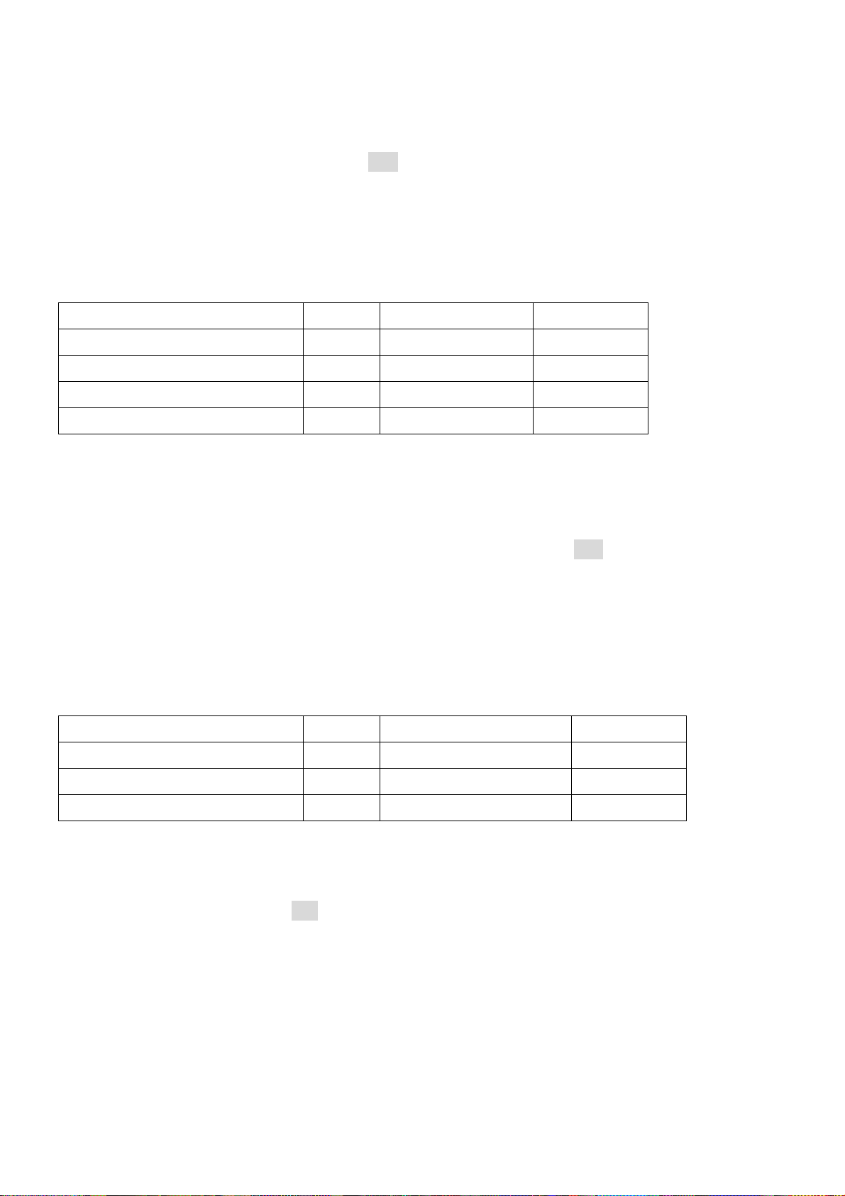
Computed Parameter Code Measuring Range Min Span
Relative Humidity (RH) 0 1 ~ 99 % 10 %
Absolutely Humidity (AH) 1 0 ~ 600 g/M
3
60 g/M
3
Mixing Ratio (MR) 2 0 ~ 600 g/Kg 60 g/Kg
Specific Enthalpy (SE) 3 0 ~ 999 kj/Kg 100 kj/Kg
Table 2 Ch #1 Computed Parameter Code and Measuring Range
3.2.2 Select Ch # 2 Computed Parameter function < 5-2 >
The Air Temperature (Ta), Dew Point Temperature (Td) or Wet Bulb Temperature (Tw) can be
selected for Transmitting, Displaying and Alarm. The display prompt 5-2 is displayed on the
upper LED module. Press the ENTER key, the transmitter will respond by displaying the existing
Computed Parameter Code displayed on the lower LED module. Use the UP key or DOWN key
select the Code until the code is set correctly. Press the ENTER key again to save and quit the
function. Default Code is 4. Note: when pressing keypads please hold until the displayed status
has changed,
Computed Parameter Code
Measuring Range (℃) Min Span (℃)
Air Temperature (Ta) 4 - 30 ~ 100 10
Dew Point Temperature (Td) 5 - 40 ~ 60 10
Wet Bulb Temperature (Tw) 6 - 40 ~ 60 10
Table 3 Ch #2 Computed Parameter Code and Measuring Range
3.2.3 Set Ch#1 Lower Range Value @ 4mA ( ZERO) function < 5-3>
The function display prompt is S-3 displayed on the upper LED module. Press the ENTER key,
the transmitter will respond by displaying the existing ZERO value on the lower LED module. Use
the UP key or DOWN key to increase /decrease the displayed value until the value is set
correctly. Press the ENTER key again to save and quit the function. The adjustable ZERO range
is from 0 to SPAN-10
12
Page 14

3.2.4 Set Ch #1 Higher Range Value @ 20 mA (SPAN) function < 5-4 >
The function display prompt is S-4 displayed on the upper LED module. Press the ENTER key,
the transmitter will response by displaying the existing SPAN value on the lower LED module.
Use the UP key or DOWN key to increase /decrease the value until the value is set correctly.
Press the ENTER key again to save and quit the function. The adjustable SPAN range is from
ZERO+10 to Maximum measuring range
3.2.5 Set Ch #2 Lower Range Value @ 4mA ( ZERO) function < 5-5>
The function display prompt is S-5 displayed on the upper LED module. Press the ENTER key,
the transmitter will response by displaying the existing ZERO value on the lower LED module.
Use the UP key or DOWN key to increase /decrease the displayed value until the value is set
correctly. Press the ENTER key again to save and quit the function. The adjustable ZERO range
is from 0 to SPAN-10
3.2.6 Set Ch #2 Higher Range Value @20 mA (SPAN) function < 5-6 >
The function display prompt is S-6 displayed on the upper LED module. Press the ENTER key,
the transmitter will response by displaying the existing SPAN value on the lower LED module.
Use the UP key or DOWN key to increase /decrease the value until the value is set correctly,
Press the ENTER key again to save and quit the function. The adjustable SPAN range from
ZERO+10 to Maximum measuring range
3.2.7 Set Ch#1 Fail Safe Reporting function < 5-7 >
Fail-safe reporting allows the transmitter to change the 4-20mA loop to indicate a failure
condition. This failure may be a sensor failure or a transmitter failure. The function display
prompt is S-7 displayed on the upper LED module. Press the ENTER key, the transmitter will
response by displaying the existing Code on the lower LED module. Use the UP key or DOWN
key to increase /decrease the Code until the value is set correctly . Press the ENTER key again to
save and quit the function. Code=0 means loop current less than 3.8 mA (Downscale). Code=1
means loop current above 21 mA (Upscale). Default Code is 0
Fail-safe reporting Code
Downscale 0
Upscale 1
Table 6 Ch #1 & Ch #2 Fail Safe Reporting
3.2.8 Set Ch#2 Fail Safe Reporting function < 5-8 >
Fail-safe reporting allows the transmitter to change the 4-20mA loop to indicate a failure
condition. This failure may be a sensor failure or a transmitter failure. The function display
prompt is S-8 displayed on the upper LED module. Press the ENTER key, the transmitter will
response by displaying the existing Code on the lower LED module. Use the UP key or DOWN
13
Page 15

key to increase /decrease the Code until the value is set correctly . Press the ENTER key again to
save and quit the function. Code=0 means loop current less than 3.8 mA (Downscale). Code=1
means loop current above 21 mA (Upscale). Default Code is 0
3.2.9 Set Ch#1 Lower Trip Point Value (LTP) function < 5-9 >
The function display prompt is S-9 displayed on the upper LED module. Press the ENTER key,
the transmitter will respond by displaying the existing Lower Trip Point value on the lower LED
module. Use the UP key or DOWN key to increase /decrease the value until the value is set
correctly. Press the ENTER key again to save and quit the function. The Lower Trip Point Value
must be greater than ZERO.
3.2.10 Set Ch#1 Higher Trip Point Value (HTP) function < 510 >
The function display prompt is S10 displayed on the upper LED module. Press the ENTER key,
the transmitter will response by displaying the existing Higher Trip Point value on the lower LED
module. Use the UP key or DOWN key to increase /decrease the value until the value is set
correctly. Press the ENTER key again to save and quit the function. The Higher Trip Point Value
must be less than SPAN.
3.2.11 Set Ch#2 Lower Trip Point Value (LTP) function < 511 >
The function display prompt is S11 displayed on the upper LED module. Press the ENTER key,
the transmitter will respond by displaying the existing Lower Trip Point value on the lower LED
module. Use the UP key or DOWN key to increase /decrease the value until the value is set
correctly. Press the ENTER key again to save and quit the function. The Lower Trip Point Value
must be greater than ZERO.
3.2.12 Set Ch#2 Higher Trip Point Value (HTP) function < 512 >
The function display prompt is S12 displayed on the upper LED module. Press the ENTER key,
the transmitter will response by displaying the existing Higher Trip Point value on the lower LED
module. Use the UP key or DOWN key to increase /decrease the value until the value is set
correctly. Press the ENTER key again to save and quit the function. The Higher Trip Point Value
must be less than SPAN.
Note: The relationship of ZERO ≦ LTP < HTP ≦ SPAN must be followed
3.2.13 Set Ch #1 & Ch #2 Dead Band (Hysteresis) of Trip Point function < 513 >
The function display prompt is S13 displayed on the upper LED module. Press the ENTER key,
the transmitter will respond by displaying the existing Dead Band value on the lower LED module.
Use the UP key or DOWN key to increase /decrease the value until the value is set correctly.
Press the ENTER key again to save and quit the function. Default value is 1
WARNING: The alarm should not be used for critical safety applications such as an
emergency shut down system.
14
Page 16

3.2.14 Set Ch #1 Alarm Mode function < 514 >
The function display prompt is S14 displayed on the upper LED module. Press the ENTER key,
the transmitter will respond by displaying the existing Alarm Mode Code on the lower LED
module. Use the UP key or DOWN key to increase /decrease the code until the code is set
correctly. Press the ENTER key again to save and quit the function. Default Code is 0.
Alarm Mode Code
Disable 0
Mode 1 1
Mode 2 2
Mode 3 3
Mode 4 4
Table 7 Ch #1 Alarm code
15
Page 17
3.2.15 Set Ch #2 Alarm Mode function < 515 >
The function display prompt is S15 displayed on the upper LED module. Press the ENTER key,
the transmitter will respond by displaying the existing Alarm Mode Code on the lower LED
module LED. Use the UP key or DOWN key to increase /decrease the code until the code is set
correctly. Press the ENTER key again to save and quit the function. Default Code is 0.
Alarm Mode Code
Disable 0
Mode 1 1
Mode 2 2
Mode 3 3
Mode 4 4
Table 7 Ch #2 Alarm code
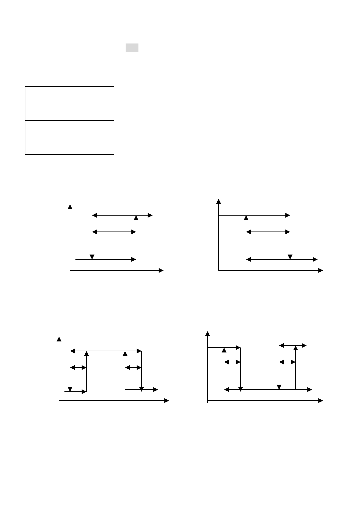
1. Mode 1: PV > Low Trip Point; Alarm tripped, SSR change position from Open to Close
2. Mode 2: PV < Low Trip Point; Alarm tripped, SSR change position from Close to Open
Switch Close Switch Close
Dead Band Dead Band
Switch Open Switch Open
LTP PV LTP PV
<Fig. 10-a > MODE 1 < Fig. 10-b > MODE 2
3. Mode 3: LTP < PV <HTP; Alarm tripped, SSR change Position from Open to Close
4. Mode 4: LTP < PV <HTP; Alarm tripped, SSR change Position from Close to Open
SW. Close SW Close
SW. Open SW. Open
LTP HTP PV LTP HTP PV
<Fig. 10-c> MODE= 3 < Fig. 10-d> MODE= 4
< Fig 10> Alarm Modes
Note: PV= Process Value. LTP= Lower Trip Point, HTP= Higher Trip Point
16
Page 18
3.2.16 Set Temperature Engineering units function < 516 >
The function display prompt is S16 displayed on the upper LED module. Press the ENTER key,
the transmitter will respond by displaying the existing temperature engineering units code on the
lower LED module. Use the UP key or DOWN key to increase /decrease the code until the code
is set correctly. Press the ENTER key again to save and quit the function. Default code is 0
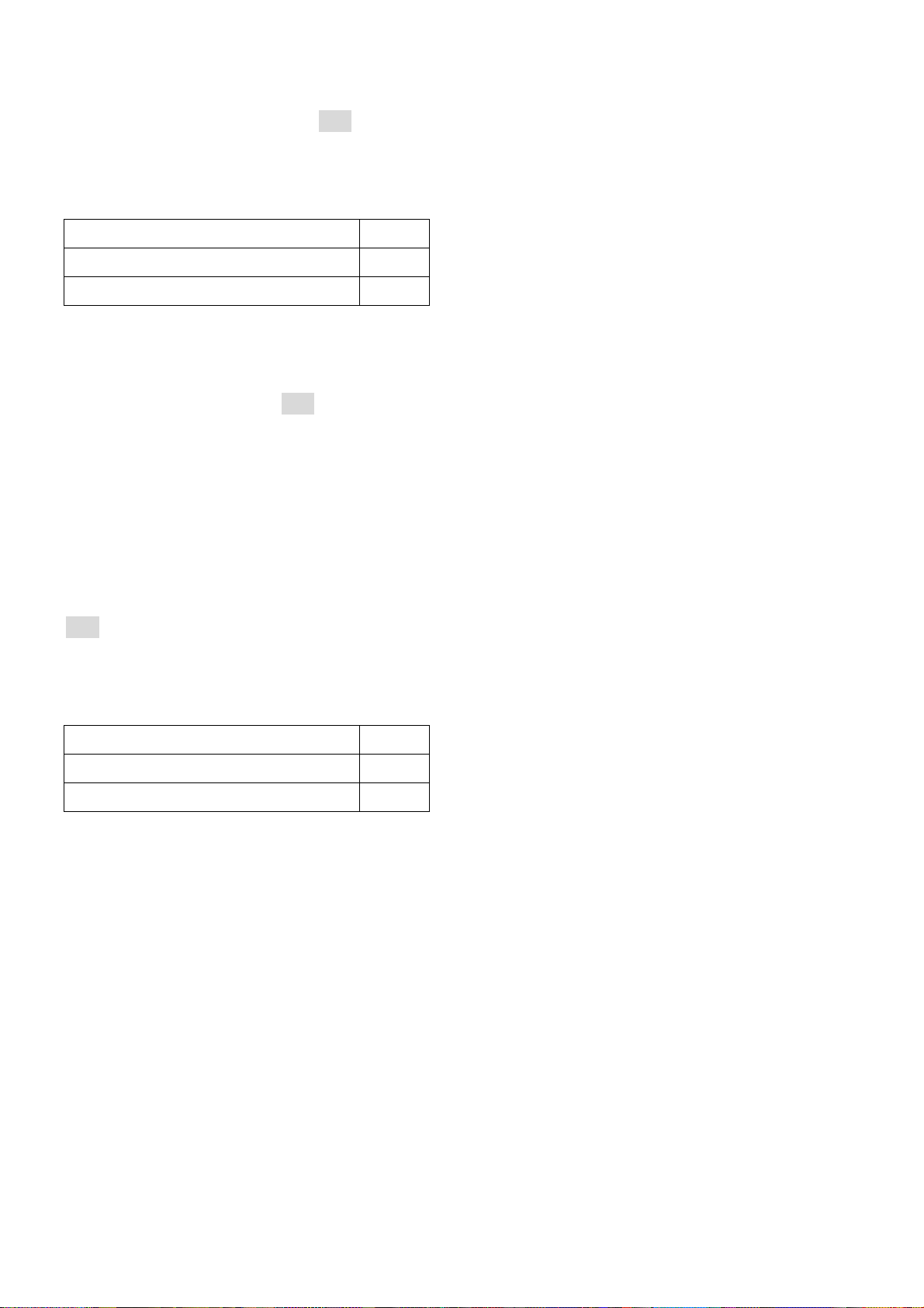
Temperature Engineering units Code
Celsius, 0
Fahrenheit 1
3.2.17 Set Local Barometric Pressure Function <517>
Barometric Pressure is required for computation of Tw, MR and SE input parameters. The
function display prompt is S17 displayed on the upper LED module. Press the ENTER key, the
transmitter will respond by displaying the existing offset value from default on the lower LED
module. Use the UP key or DOWN key to increase /decrease the offset value until the value is
set correctly. Press the ENTER key again to save and quit the function. The default Barometric
Pressure is 101.3 kP. Adjustable range: +/- 99 kP
3.2.18 Set Ch #1 or Ch #2 as a active output Function <518>
This function is used only for single loop current HX401 model. The function display prompt is
S18 displayed on the upper LED module. Press the ENTER key, the transmitter will respond by
displaying the existing code value on the lower LED module. Use the UP key or DOWN key to
increase /decrease the code until the code is set correctly. Press the ENTER key again to save
and quit the function. The default code is 1
Active output Code
Ch #1 1
Ch #2 2
17
Page 19

4. Calibrate the Transmitter
Do not start any calibration procedure without first reading and fully understanding this manual.
Improper operation may cause the loss of calibration data. The Transmitter and Calibration
Equipments need warm-up (5 minutes) before getting high performance.
4.1 Calibration Equipment:
Standard Humidity Buffer/ Chamber or Humidity Generator (Salt Solutions)
51/2 Multi-meter; Monitor output current from transmitter
Power Supply: 24 Vdc nominal
4.2 Entering the Calibration Mode
To start the Calibration Mode, first press and hold the UP key and ENTER key simultaneously
until the Calibration Mode prompt is displayed during Measuring Mode see
< Fig.7 >. The Calibration Mode will allow the user to do the following operation. See <Fig 11>
Setting Ch # 1 & Ch # 2 ZERO point 4 mA
Setting Ch # 1 & Ch # 2 SPAN point 20 mA
Field Alignment one-point Humidity Offset
Field Alignment one-point Temperature Offset
Calibration 3 points Humidity
Displayed Prompt Functions
C1L Trim Ch #1 4.00 mA
C1H Trim Ch #1 20.00 mA
C2L Trim Ch #2 4.00 mA
C2H Trim Ch #2 20.00 mA
C-3 Alignment one-point Humidity Offset
C-4 Alignment one-point Temperature Offset
C5L Calibration 11.3% RH Humidity
C5F Calibration 57.5% RH Humidity
C5H Calibration 84.5% RH Humidity
Table 8 Calibration Mode
18
Page 20
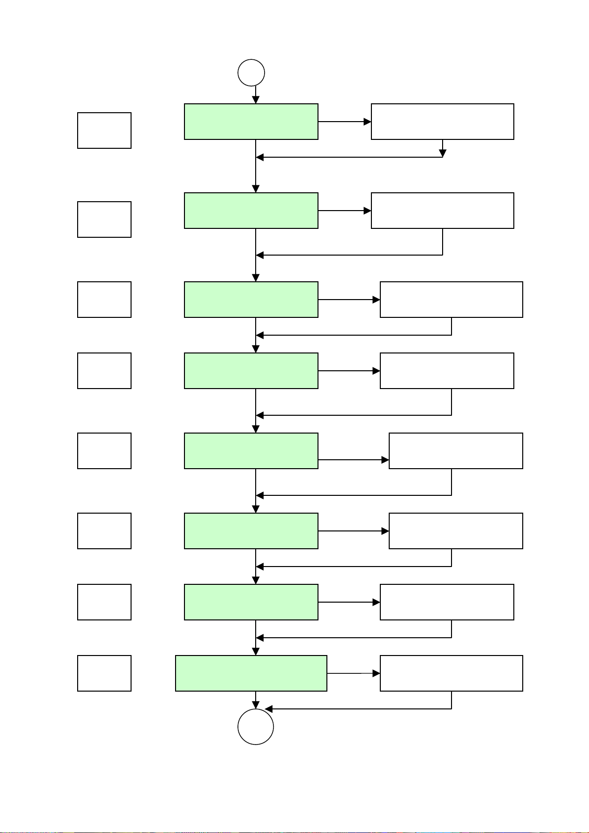
B
Prompt
ENTER
C1L
Trim Ch #1 4.00 mA
LED Displayed 4.00
UP/DOWN ENTER
ENTER
C1H
Trim Ch#1 20.00 mA
LED Displayed 20.0
ENTER
UP/DOWN
ENTER
C2L
Trim Ch #2 4.00 mA
LED Displayed 4.00
UP/DOWN ENTER
ENTER
C2H
Trim Ch #2 20.00 mA
LED Displayed 20.0
ENTER
UP/DOWN
ENTER
C-3
Adj. Humidity Offset
LED Displayed Offset
UP/DOWN ENTER
ENTER
C-4
Adj. Temp. Offset
LED Displayed Offset
UP/DOWN ENTER
ENTER
C5L
Cal. 11.3 % RH LED Displayed RH
UP/DOWN ENTER
ENTER
Cal. 57.5 % & 84.5% RH LED Displayed RH2% C5F
UP/DOWN ENTER
<Fig. 11 > Flow Chart of Calibration Mode
19
Page 21

4.2.1 Trim Ch #1 4.00 mA
The function display prompt is C1L displayed on the upper LED module. Press the ENTER key,
the transmitter will respond by displaying 4.00 on the lower LED module and will output a
milliamp current equal to its internal set 4mA. This 4 mA value should be read on an external
Multi-meter. Use the UP key or DOWN key to increase /decrease the output current until the
4.00mA current is read correctly. Press the ENTER key again to save and quit the function. It is
advisable to use a higher accuracy Multi-meter to read the output current. It is very possible that
the transmitter will be more accurate than a great many Multi-meters. In this case, trimming will
make the transmitter less accurate rather than more accurate
4.2.2 Trim Ch #1 20.00 mA
The function display prompt is C1H displayed on the upper LED module. Press the ENTER key,
the transmitter will respond by displaying 20.0 on the lower LED module and will output a
milliamp current equal to its internal set 20mA. This 20 mA value should be read on an external
Multi-meter. Use the UP key or DOWN key to increase /decrease the current until 20.00mA
current is read correctly. Press the ENTER key again to save and quit the function.
Note: These functions are only for the purpose of adjusting the loop current to be exactly
4.00/20.00 mA according to the plant’s local standard. This is not to re-range the
transmitter
4.2.3 Trim Ch #2 4.00 mA
The function display prompt is C2L displayed on the upper LED module. Press the ENTER key,
the transmitter will respond by displaying 4.00 on the lower LED module and will output a
milliamp current equal to its internal set 4mA. This 4 mA value should be read on an external
Multi-meter . Use the UP key or DOWN key to increase /decrease the output current until 4.00mA
current is read correctly. Press the ENTER key again to save and quit the function. It is advisable
to use a higher accuracy Multi-meter to read the output current. It is very possible that the
transmitter will be more accurate than a great many Multi-meters. In this case, trimming will
make the transmitter less accurate rather than more accurate
4.2.4 Trim Ch #2 20.00 mA
The function display prompt is C2H displayed on the upper LED module. Press the ENTER key,
the transmitter will respond by displaying 20.0 on the lower LED module also output a milliamp
current equal to its internal set 20mA. This 20 mA value should be read on an external
Multi-meter. Use the UP key or DOWN key to increase /decrease the current until 20.00mA
current is read correctly, press ENTER key again to save and quit the function.
Note: These functions are only for the purpose of adjusting the loop current to be exactly
4.00/20.00 mA according to the plant’s local standard. This is not to re-range the
transmitter
20
Page 22

4.2.5 Alignment one point Humidity (Humidity Offset)
The function display prompt is C-3 displayed on the upper LED module. Press the ENTER key,
the transmitter will respond by displaying the measured value on the upper LED module and will
display the offset value on the lower LED module. Press the UP/DOWN key to change the
measured value and offset value of the measured value until the measured value match as the
standard value. Press the ENTER key again to execute and quit the function Note: Replace or
re-calibrate the Humidity sensor if the humidity offset value is larger than +/- 3 % RH or
more.
4.2.6 Alignment one point Temperature (Temperature Offset)
The function display prompt is C-4 displayed on the upper LED module. Press the ENTER key,
the transmitter will respond by displaying the measured value on the upper LED module and will
display the offset value on the lower LED module. Press the UP/DOWN key to change the
measured value and offset value of the measured value until the measured value match as the
standard value. Press the ENTER key again to execute and quit the function Note: The
temperature sensor has to be replaced if the temperature offset value is larger than +/- 1
℃ or more.
4.2.7 Calibration 11.3 % RH
Place the probe into a humidity chamber or salt solutions of 11.3 % RH and wait until it settles
into equilibrium. The function display prompt is C5L displayed on the upper LED module. Press
the ENTER key, the transmitter will respond by displaying a default of 11.3 or the existing value
(last calibrated) on the lower LED module. Press the UP/DOWN key to change to the matching
chamber presented. Press the ENTER key again to execute and quit the function. The
calibration data will be displayed a short time and saved to EEPROM. Note: An error will be
displayed on the upper LED module if the calibration point is out of 10 ~12 %RH range. It is
recommended to repeat this function several times to insure the probe is in equilibration.
4.2.8 Calibration 57.5 % RH
Place the probe into a humidity chamber or salt solutions of 57.5 % RH and wait until it settles
into equilibrium. The function display prompt is C5F displayed on the upper LED module. Press
the ENTER key, the transmitter will response by displaying a default of 57.5 or existing value
(last calibrated) on lower LED module, press UP/DOWN key to change to the matching chamber
presented. Press the ENTER key again to execute and quit the function. The calibration data will
be displayed a short time and saved to EEPROM. Note: An error will be displayed on the upper
LED module if calibration point out of 56~ 60 %RH range. It is recommended to repeat this
function several times to insure the probe is in equilibration
4.2.9 Calibration 84.3 % RH
Place the probe into a humidity chamber or salt solutions of 84.3 % RH and wait until it settles
21
Page 23
into equilibrium. The function display prompt is C5H displayed on the upper LED module. Press
the ENTER key, the transmitter will respond by displaying a default of 84.3 or existed value (last
calibrated) on the lower LED module. Press the UP/DOWN key to change to the matching
chamber presented. Press the ENTER key again to execute and quit the function. The
calibration data will be displayed a short time and saved to EEPROM. Note: An error displayed
on the upper LED module if calibration point out of 82~ 86 %RH range.
It is recommended to repeat this function several times to insure the probe is in equilibration
5. Application and Maintenance
Please avoid any high concentration of volatile & aggressive chemical solvent vapors or other
organic compounds or Acids and bases such as Ketenes, Acetone, Ethanol, Isopropyl Alcohol,
Toluene, HCL, H2SO4, HNO3, NH3, H2O2,Ozone etc or exposure to extreme high humidity and
temperature conditions for extended time periods (may offset the sensor output). If these
happens, the following conditioning procedure may bring the sensor back to calibration state.
Baking: 100 ~ 105
at less 5% RH for 10 hours.
Re-Hydration: 20 ~ 30 at > 75% RH for 12 hours
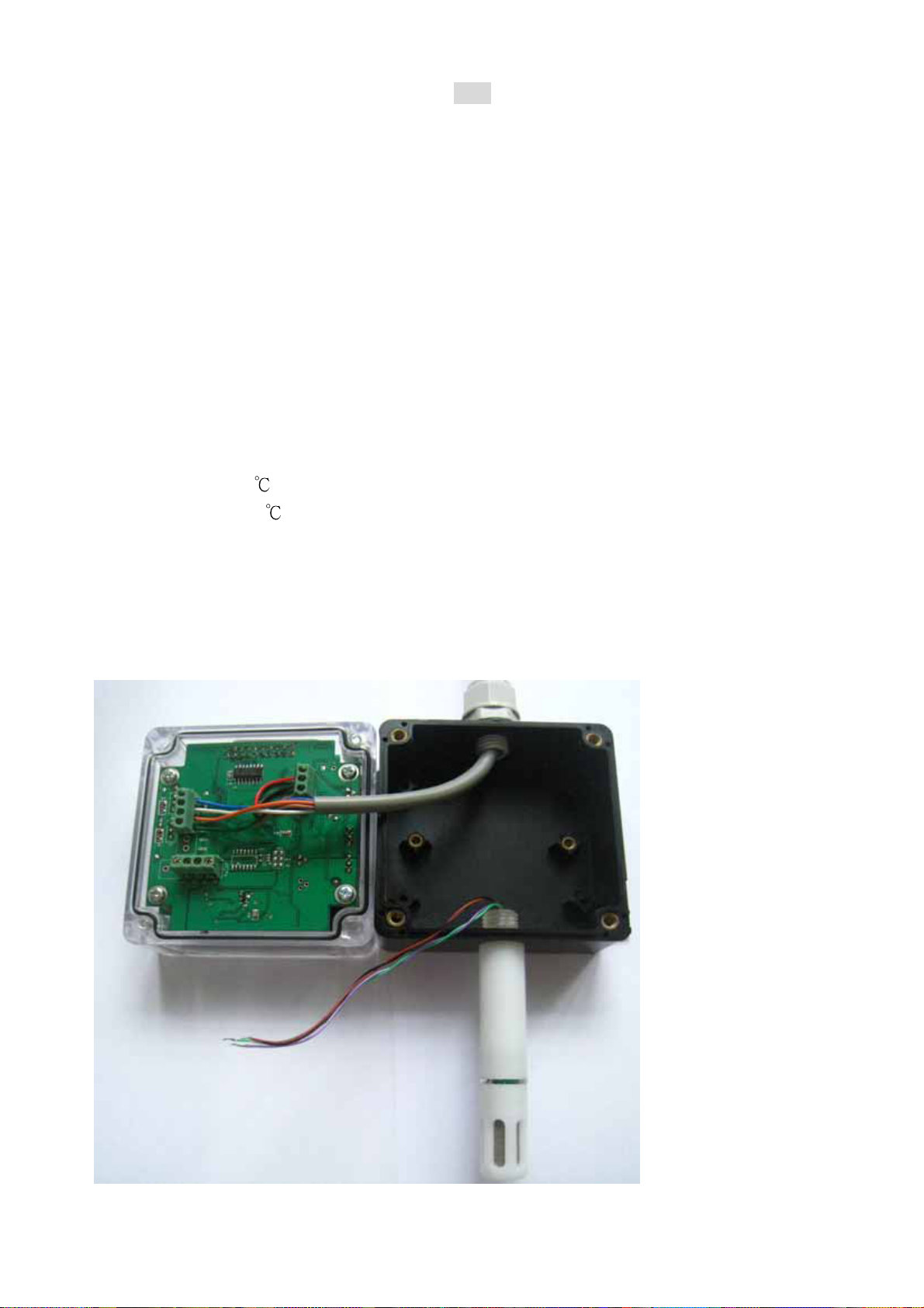
5.1 Sensor replacement
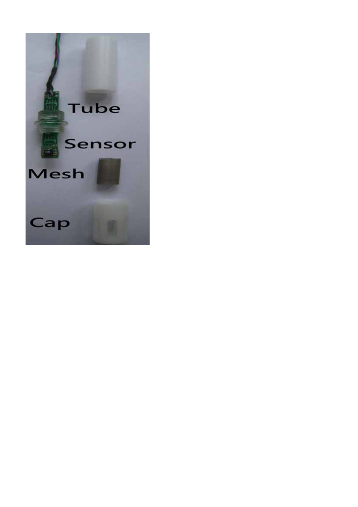
Power-off the unit. Open the HX400,loosen the sensor input wires as picture represent. Remove
the Cap from probe by counterclockwise turns (recommend pliers to hold the limpid area of the
probe). Loosen & remove the sensor PCB from Tube.
22
Page 24
6. Error Code
When the sensor input wires are broken, or beyond acceptable range or the internal components
fail the instrument will display error symptoms for revealing the cause of the fault.
Err3: Humidity/Temperature sensor input wires are broken or the input signal is beyond the
acceptable range. Check input wires
Err4 ~8: Internal Calibration data failure. Need to re-calibrate again or Return to Omega
Engineering for repair
7. Model
HX401W Single Loop; Wall mounted
Probe length 80 mm
HX401R Single Loop; Remote type
Wire length 100 cm
HX401D Single Loop; Duct mounted
Probe length 230 mm
HX402W Dual Loop; Wall mounted
Probe length 80 mm
HX402R Dual Loop; Remote type
Wire length 100 cm
HX402D Dual Loop; Duct mounted
Probe length 230 mm
23
Page 25

WARRANTY/DISCLAIMER
OMEGA ENGINEERING, INC. warrants this unit to be free of defects in materials and workmanship for a
period of 13 months from date of purchase. OMEGA’s WARRANTY adds an additional one (1) month
grace period to the normal one (1) year product warranty to cover handling and shipping time. This
ensures that OMEGA’s customers receive maximum coverage on each product.
If the unit malfunctions, it must be returned to the factory for evaluation. OMEGA’s Customer Service
Department will issue an Authorized Return (AR) number immediately upon phone or written request.
Upon examination by OMEGA, if the unit is found to be defective, it will be repaired or replaced at no
charge. OMEGA’s WARRANTY does not apply to defects resulting from any action of the purchaser,
including but not limited to mishandling, improper interfacing, operation outside of design limits,
improper repair, or unauthorized modification. This WARRANTY is VOID if the unit shows evidence of
having been tampered with or shows evidence of having been damaged as a result of excessive corrosion;
or current, heat, moisture or vibration; improper specification; misapplication; misuse or other operating
conditions outside of OMEGA’s control. Components in which wear is not warranted, include but are not
limited to contact points, fuses, and triacs.
OMEGA is pleased to offer suggestions on the use of its various products. However,
OMEGA neither assumes responsibility for any omissions or errors nor assumes liability for any
damages that result from the use of its products in accordance with information provided by
OMEGA, either verbal or written. OMEGA warrants only that the parts manufactured by it will be
as sp ecified and f ree of defects. OMEGA M AKES N O OT HER WARRANT IES OR
REPRESENTATIONS OF ANY KIND WHATSOEVER, EXPRESS OR IMPLIED, EXCEPT THAT OF TITLE,
AND ALL IMPLIED WARRANTIES INCLUDING ANY WARRANTY OF MERCHANTABILITY AND
FI TNESS FOR A PARTICULAR PURP OSE ARE HEREBY DISCLAIMED. L IMITATION OF
LIABILITY: The remedies of purchaser set forth herein are exclusive, and the total liability of
OMEGA with respect to this order, whether based on contract, warranty, negligence,
indemnification, strict liability or otherwise, shall not exceed the purchase price of the
co mponent upon w hich l iability is based. I n no event shall OMEGA be li able f or
consequential, incidental or special damages.
CONDITIONS: Equipment sold by OMEGA is not intended to be used, nor shall it be used: (1) as a “Basic
Component” under 10 CFR 21 (NRC), used in or with any nuclear installation or activity; or (2) in medical
applications or used on humans. Should any Product(s) be used in or with any nuclear installation or
activity, medical application, used on humans, or misused in any way, OMEGA assumes no responsibility
as set forth in our basic WARRANTY/ DISCLAIMER language, and, additionally, purchaser will indemnify
OMEGA and hold OMEGA harmless from any liability or damage whatsoever arising out of the use of the
Product(s) in such a manner.
RETURN REQUESTS/INQUIRIES
Direct all warranty and repair requests/inquiries to the OMEGA Customer Service Department. BEFORE
RETURNING ANY PRODUCT(S) TO OMEGA, PURCHASER MUST OBTAIN AN AUTHORIZED RETURN
(AR) NUMB E R FR O M OME GA’S CU STOM E R SE RV I CE DE PARTMEN T (IN ORDE R TO AV OID
PROCESSING DELAYS). The assigned AR number should then be marked on the outside of the return
package and on any correspondence.
The purchaser is responsible for shipping charges, freight, insurance and proper packaging to prevent
breakage in transit.
FOR WARRANTY
following information available BEFORE
contacting OMEGA:
1. Purchase Order number under which the product
was PURCHASED,
2. Model and serial number of the product under
warranty, and
3. Repair instructions and/or specific problems
relative to the product.
OMEGA’s policy is to make running changes, not model changes, whenever an improvement is possible. This affords
our customers the latest in technology and engineering.
OMEGA is a registered trademark of OMEGA ENGINEERING, INC.
© Copyright 2012 OMEGA ENGINEERING, INC. All rights reserved. This document may not be copied, photocopied,
reproduced, translated, or reduced to any electronic medium or machine-readable form, in whole or in part, without the
prior written consent of OMEGA ENGINEERING, INC.
RETURNS, please have the
FOR NON-WARRANTY REPAIRS,
for current repair charges. Have the following
information available BEFORE contacting OMEGA:
1. Purchase Order number to cover the COST
of the repair,
2. Model and serial number of the product, and
3. Repair instructions and/or specific problems
relative to the product.
consult OMEGA
Page 26

Where Do I Find Everything I Need for
Process Measurement and Control?
OMEGA…Of Course!
Shop online at omega.com
sm
TEMPERATURE
䡺⻬
Thermocouple, RTD & Thermistor Probes, Connectors, Panels & Assemblies
䡺⻬
Wire: Thermocouple, RTD & Thermistor
䡺⻬
Calibrators & Ice Point References
䡺⻬
Recorders, Controllers & Process Monitors
䡺⻬
Infrared Pyrometers
PRESSURE, STRAIN AND FORCE
䡺⻬
Transducers & Strain Gages
䡺⻬
Load Cells & Pressure Gages
䡺⻬
Displacement Transducers
䡺⻬
Instrumentation & Accessories
FLOW/LEVEL
䡺⻬
Rotameters, Gas Mass Flowmeters & Flow Computers
䡺⻬
Air Velocity Indicators
䡺⻬
Turbine/Paddlewheel Systems
䡺⻬
Totalizers & Batch Controllers
pH/CONDUCTIVITY
䡺⻬
pH Electrodes, Testers & Accessories
䡺⻬
Benchtop/Laboratory Meters
䡺⻬
Controllers, Calibrators, Simulators & Pumps
䡺⻬
Industrial pH & Conductivity Equipment
DATA ACQUISITION
䡺⻬
Data Acquisition & Engineering Software
䡺⻬
Communications-Based Acquisition Systems
䡺⻬
Plug-in Cards for Apple, IBM & Compatibles
䡺⻬
Data Logging Systems
䡺⻬
Recorders, Printers & Plotters
HEATERS
䡺⻬
Heating Cable
䡺⻬
Cartridge & Strip Heaters
䡺⻬
Immersion & Band Heaters
䡺⻬
Flexible Heaters
䡺⻬
Laboratory Heaters
ENVIRONMENTAL
MONITORING AND CONTROL
䡺⻬
Metering & Control Instrumentation
䡺⻬
Refractometers
䡺⻬
Pumps & Tubing
䡺⻬
Air, Soil & Water Monitors
䡺⻬
Industrial Water & Wastewater Treatment
䡺⻬
pH, Conductivity & Dissolved Oxygen Instruments
M5148/0512
 Loading...