

Page 1
®
RoHS 2 Compliant
User’s Guide
Shop online at
omega.com
e-mail: [email protected]
For latest product manuals:
omegamanual.info
®
HX15
High Temperature
Relative Humidity/Temperature
Probe Transmitter
Page 2

OMEGAnet®Online Service Internet e-mail
omega.com [email protected]
Servicing North America:
U.S.A.: Omega Engineering, Inc., One Omega Drive, P.O. Box 4047
ISO 9001 Certified
Canada: 976 Bergar, Laval (Quebec), H7L 5A1 Canada
Stamford, CT 06907-0047 USA
Toll-Free: 1-800-826-6342 Tel: (203) 359-1660
FAX: (203) 359-7700 e-mail: [email protected]
For immediate technical or application assistance:
U.S.A. and Canada: Sales Service: 1-800-826-6342/1-800-TC-OMEGA
Customer Service: 1-800-622-2378/1-800-622-BEST
Engineering Service: 1-800-872-9436/1-800-USA-WHEN
®
®
®
Servicing Asia:
China: 1698 Yi Shan Road, Unit 102, Min Hang District
Shanghai, China 201103 P.R.C.
Hotline: 800 819 0559/400 619 0559
e-mail: [email protected]
Servicing Europe:
Benelux: Toll-Free: 0800 099 3344 TEL: +31 20 347 21 21
Czech Republic: Frystatska 184, 733 01 Karviná, Czech Republic
France: Toll-Free: 0805 466 342 TEL: 01 57 32 48 17
Germany/ Austria: Daimlerstrasse 26, D-75392 Deckenpfronn, Germany
United Kingdom: OMEGA Engineering Ltd.
ISO 9001 Certified
FAX: +31 20 643 46 43 e-mail: [email protected]
TEL: +420-59-6311899 FAX: +420-59-6311114
e-mail: [email protected]
FAX: 01 57 32 48 18 e-mail: [email protected]
Toll-Free: 0800 8266342 TEL: +49 (0) 7056 9398-0
FAX: +49 (0) 7056 9398-29 e-mail: [email protected]
One Omega Drive, River Bend Technology Centre, Northbank
Irlam, Manchester M44 5BD United Kingdom
Toll-Free: 0800-488-488 TEL: +44 (0) 161 777-6611
FAX: +44 (0) 161 777-6622 e-mail: [email protected]
It is the policy of OMEGA Engineering, Inc. to comply with all worldwide safety and EMC/EMI
regulations that apply. OMEGA is constantly pursuing certification of its products to the European
New Approach Directives. OMEGA will add the mark to every appropriate device upon
certification.
The information contained in this document is believed to be correct, but OMEGA accepts no liability for any
errors it contains, and reserves the right to alter specifications without notice.
WARNING: These products are not designed for use in, and should not be used for, human applications.
Page 3

TABLE OF CONTENTS
A. General Description 1.
B. Unpacking 1.
C. Theory of Operation 2.
D. Terminal Connections 3.
E. Wiring Example 3.
F. Mounting 4.
G. Calculations 5.
H. R H Calibration 6.
I. Temp. Calibration 7.
J. Maintenance 7.
K. Specifications 8.
A. GENERAL DESCRIPTION
The stainless steel probe provides relative humidity as well as
temperature out puts. A thin film polymer capacitor senses relative
humidity, while temperature is monitored by a 1000 Ohm platinum
RTD. The sensors are protected by a stainless steel filter cap easily
removed for cleaning. The probe is connected to an electronics
enclosure with a 40 inch (1m) Teflon cable. The enclosure contains
the calibration trimmers, signal and power connections via two
terminal blocks. The probe is available in two configurations, as a
2.5” (64 mm) probe with a wall mounting clip, and as an 8.5” (216
mm) probe with an adjustable duct flange.
B. UNPACKING
Verify that the following parts have been received.
1. Remove probe with cable and electronics enclosure.
2. Instruction manual.
3. Wall mounting clip [for 2.5” (64 mm) probe].
4. 2 piece duct flange, with o-ring, (3) screws, and a gasket.
[for 8.5” (216 mm) probe]
1
Page 4

22 15 OHMS
18 6 OHMS
C. THEORY OF OPERATION
A 4 to 20 milliamp loop is a series current loop in which a
transmitter will vary the current flow depending upon the parameter
being measured (Relative Humidity or Temperature). Advantages of
a current output over a voltage output is that is less susceptible to
noise interference and allows the connection of more than one meter
or recorder to the loop as long as the maximum resistance is not
exceeded.
The typical current loop will consist of a power supply, transmitter,
and a meter to measure the current flow. The loop resistance is the
sum of the impedance of the meter(s) and the lead wire. The
maximum allowable loop impedance of the probe is found by the
Formula:
Rmax = (power supply voltage-7 volts) /.02 amps
Example: when using a 24 VDC power supply:
Rmax= (24-7) /.02=850 ohms (for total wire length to and
from the transmitter).
AWG WIRE SIZE RESISTANCE PER 1000 FEET
24 25 OHMS
20 10 OHMS
16 4 OHMS
If the meter or recorder being used accepts only voltage, convert the
current to voltage by installing a 250 ohm resistor across the input
terminals of the recorder to obtain a 1 to 5 volts input.
2
Page 5
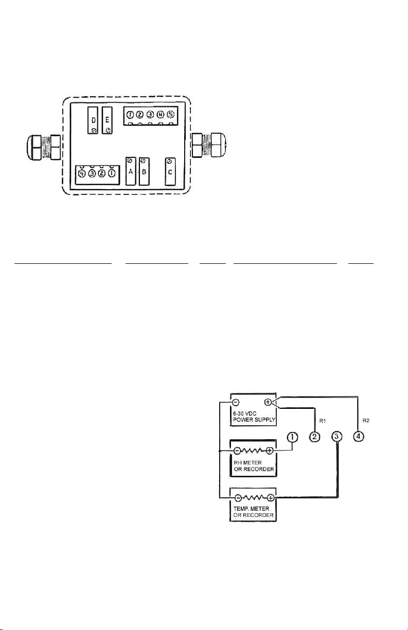
E. WIRING EXAMPLES
TYPICAL CURRENT HOOKUP
Wires R1 and R2 can be combined
into one single wire with a jumper
at pins (4) and (2). This will result
in 3 wires instead of 4.
TRIMPOTS TYPE
A. RH GAIN
B. RH ZERO
C. RH OFFSET
D. TEMP GAIN
E. TEMP ZERO
PROBE TERMINALS CABLE WIRE TYPE OUTPUT TERMINALS TYPE
1 black RTD 1 -RH
2 white RTD 2 +RH
3 green RH 3 -TEMP
4 red RH 4 +TEMP
5 shield ___
D. TERMINAL CONNECTIONS AND TRIM POTS
3
Page 6
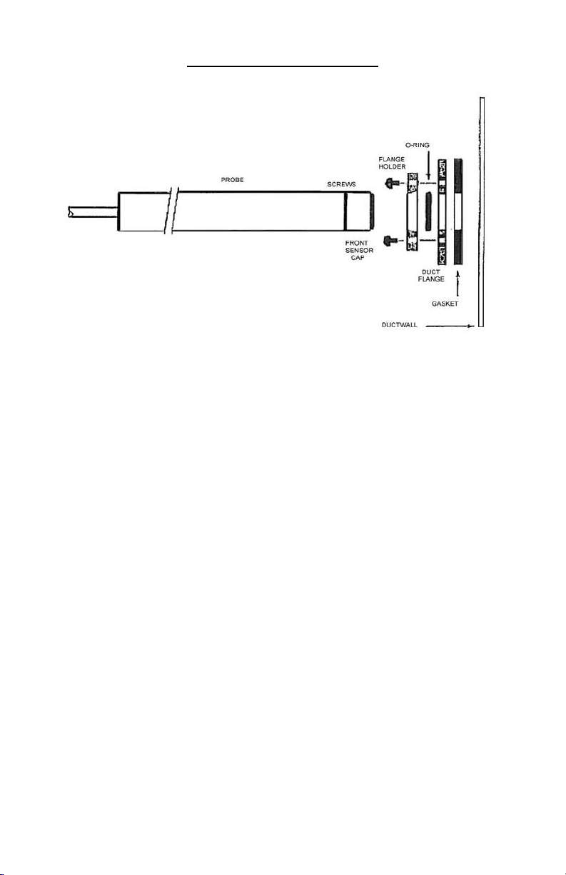
F. MOUNTING
A. DUCT MOUNTING
STEPS
1. Slide flange holder onto probe with countersink
hole facing front of probe as shown.
2. Position o-ring on probe at desired position (for depth into
duct).
3. Slide duct flange onto probe as shown.
4. Fasten with (3) 6/32 screws and tighten evenly until secure.
5. Position gasket between duct flange and duct wall and fasten
assembly to duct with (4) #6 sheet metal screws (not
included).
6. Loosening the 6/32 screws allows for repositioning or
removal of the probe without having to remove the duct
flange from the wall.
The duct wall requires a 11/16” (.684” or 17.5 mm) hole for
probe, with (4) mounting holes (for #6 sheet metal screws)
evenly spaced on a 2.0” (51 mm) circle. Use duct flange as
template.
B. WALL MOUNTING
PROBE INSTALLATION
1. Fasten metal clip to wall.
2. Snap probe into clip.
4
Page 7

G. RH AND TEMPERATURE CALCULATIONS
1. Maximum current loop impedance for RH or temperature.
Rmax = (V supply – 7 volts) /.02 amps
2. RH current output (i = current output in milliamperes)
3. Temperature current output.
oC = (i-4) x 220/16) – 40 iC = (oC + 40) x (16/220) + 4
oF = (i-4) x (396/16) – 40 iF = (oF + 40) x (16/396) + 4
The upper limit of the humidity measurement range decreases based on
temperature. The humidity measurement limit decreases as follows:
2.20% per °C from 95 to 120°C (1.11% per °F from 203 to 248°F)
1.00% per °C from 120 to 140°C (0.56% per °F from 248 to 284°F)
0.50% per °C from 140 to 160°C (0.28% per °F from 284 to 320°F)
0.25% per °C from 160 to 180°C (0.14% per °F from 320 to 356°F)
For example, at 120°C the upper humidity limit decreases to about 45%
((120-95)(2.20%) = 55% decrease which is 45%), at 180°C it is reduced
to about 10%.
To calculate the RH accuracy, we’ll use the accuracy specs given in the
specifications section:
+/-2%RH at 25°C and -40° to 150°C at 0.05 % RH/°C.
To clarify lets take an example,
RH accuracy at 120°C,
=+/- (2% + (120-25)0.05%) = +/- (2% + 4.75%)
=+/-6.75%
So the accuracy at 120°C is +/- 6.75% and the upper humidity
measurement limit is 45% RH.
5
Page 8

H. RH CALIBRATION
Refer to Section D for the location of trim pots A and B.
Note: The HX92-CAL Relative Humidity Calibration Kit is for
providing the “low” and “high” RH environments for this procedure.
The salt solutions in this kit are prepared according to ASTM
standard E104 -85 to provide 11.3% and 75.3% relative humidity
environments. The containers provided in the kit are designed to fit with
these instruments.
1. Turn the span (trim pot A) all the way up (clockwise).
2. Turn the zero (trim pot B) all the way down (counterclockwise).
3. Place the s
at least one hour for stabilization or until the output stops
changing.
4. Verify the output is 4 +/-.02 mA. If it is not, return the unit
to Omega for evaluation and repair.
5. Adjust the zero (trim pot B) to the point where it just starts to
cause a change in the output.
6. Place the sensor in the high (75.3%) RH environment. Allow
at least one hour for stabilization or until the output stops
changing.
7. Adjust the span (trim pot A) so the output is
the difference between low and high RH environments.
Example: 75.3%-11.3% = 64% which is equivalent to 14.24
mA.
8. Adjust the sensor in the low RH environment and allow at
least one hour for stabilization or until the output
changing. Verify the output is equivalent to the low RH
environment. Example: 11.3% is equivalent to 5.81 mA.
enso
r in the low (11.3%) RH environment. Allow
equ
ivalent to
stops
6
Page 9

I. TEMPERATURE CALIBRATION
Temperature is factory calibrated only, and does not require
any further calibrations.
J. MAINTENANCE
If the probe is operated in a dusty environment, the
protective sensor filter, if clogged, may be removed for cleaning.
Unscrew filter and gently blow compressed air through screen.
If necessary, use a soft brush to remove lint from sensors.
If the sensors are subjected to 100% condensation, they must be
dried to obtain correct readings. There is no permanent
calibration shift, nor is recalibration necessary if 100%
condensation occurs.
The instrument should not be exposed to high
Concentrations of ammonia or alcohol vapors. However,
any environment that is breathable under normal HVAC
applications should not affect the sensors. To maintain original
specifications, it is generally recommended that the RH sensor
be recalibrated on an annual basis depending upon operating
conditions. The temperature sensor does not require calibration.
7
Page 10

K. SPECIFICATIONS
1. Relative Humidity: Thin film polymer capacitor.
Input Voltage Range: 7 to 30 VDC (polarity protected).
Range, Accuracy: 3% RH to 95% RH (@-40 to 95°C)*, ±2%RH at 25°C
Typical Temp. Characteristics: -40°C to 150°C at .05%RH/°C
Output: 4 to 20 mA. For 0%RH to 100%RH.
Time Constant: Under 30 seconds, 90% response at 25°C in 1M/sec air.
* See RH and Temperature Calculations section for full range.
2. Temperature: Thin film 1000 ohm platinum RTD.
Input Voltage Range: 7 to 30 VDC (polarity protected).
Range, Accuracy: -40°C to 180°C (-40°F to 356°F), ±0.5°C (±1°F)
Output: 4 to 20 ma. For -40°C to 180°C (-40°F to 356°F)
Time Constant: Under 4 seconds, 60% response in 1m/sec air.
3. Mechanical
Standard Probe: Stainless steel, 2.5” (64 mm) x .625” (16 mm)
diameter. 40” (1m) Teflon cable, metal wall mounting clip.
Duct Probe: Stainless steel, 8.5” (216 mm) x .625” (16 mm)
diameter. 40” (1m) Teflon cable.
Duct Flange: 2.75” (70mm) dia., duct hole 11/16 (.684”,
17.5 mm) dia. With 4 mounting holes .156(4 mm)
diameter (for #6 sheet metal screws), on 2.00”
(51mm) circle.
Electronics: Operating temp. -20°C to 70°C(-4°F to 158°F)
ABS housing 4.72” (120 mm) x 3.14” (80 mm) x
2.16” (55 mm) H meets NEMA 1,2,3,4,4X,5,12
and 13 specifications.
Connectors: Liquid-tight with neoprene gland for .09” to .265”
diameter cable.
4-pin plug in screw terminal block for output connections.
5-pin screw terminal block for cable wire input
connections, accepts #14 to #22 AWG wires.
Weight: 2.5” (64 mm) probe with housing 14 oz. (397 grams).
8.5” (216 mm) probe with housing and flange 20 oz. (567
grams).
8
Page 11

WARRANTY/DISCLAIMER
OMEGA ENGINEE RI NG, I NC . war rants t his uni t to be f ree o f defects i n mat erials and
workmanship for a period of 37 months from date of purchase. OMEGA’s WARRANTY adds
an additional one (1) month grace period to the normal three (3) year product warranty to
cover handling and shipping time. This ensures that OMEGA’s customers receive maximum
coverage on each product.
If the unit malfunctions, it must be returned to the factory for evaluation. OMEGA’s Customer
Service Department will issue an Authorized Return (AR) number immediately upon phone or
written request. Upon examination by OMEGA, if the unit is found to be defective, it will be
repaired or replaced at no charge. OMEGA’s WARRANTY does not apply to defects resulting
from any a ct ion of the purchase r, including but n ot limited t o mish andling, improper
interfacing, operation outside of design limits, improper repair, or unauthorized modification.
This WARRANTY is VOID if the unit shows evidence of having been tampered with or shows
evidence of having been damaged as a result of excessive corrosion; or current, heat, moisture
or vibration; improper specification; misapplication; misuse or other operating conditions
outside of OMEGA’s control. Components in which wear is not warranted, include but are not
limited to contact points, fuses, and triacs.
OMEGA is pleased to offer suggestions on the use of its various products. However,
OMEGA neither assumes responsibility for any omissions or errors nor assumes
liability for any damages that result from the use of its products in accordance with
information provided by OMEGA, either verbal or written. OMEGA warrants only
that the parts manufactured by the company will be as specified and free of
defects. OMEGA MAKES NO OTHER WARRANTIES OR REPRESENTATIONS OF ANY
KIND WHATSOEVER, EXPRESSED OR IMPLIED, EXCEPT THAT OF TITLE, AND ALL
IMPLIED WARRANTIES INCLUDING ANY WARRANTY OF MERCHANTABILITY AND
FITNESS FOR A PARTICULAR PURPOSE ARE HEREBY DISCLAIMED. LIMITATION OF
LIABILITY: The remedies of purchaser set forth herein are exclusive, and the total
liability of OMEGA with respect to this order, whether based on contract, warranty,
negligence, indemnification, strict liability or otherwise, shall not exceed the
purchase price of the component upon which liability is based. In no event shall
OMEGA be liable for consequential, incidental or special damages.
CONDITIONS: Equipment sold by OMEGA is not intended to be used, nor shall it be used: (1)
as a “Basic Component” under 10 CFR 21 (NRC), used in or with any nuclear installation or
activity; or (2) in medical applications or used on humans. Should any Product(s) be used in or
with any nuclear installation or activity, medical application, used on humans, or misused in
any way, OMEGA assumes no responsibility as set forth in our basic WARRANTY/ DISCLAIMER
language, and, additionally, purchaser will indemnify OMEGA and hold OMEGA harmless from
any liability or damage whatsoever arising out of the use of the Product(s) in such a manner.
Direct all warranty and repair requests/inquiries to the OMEGA Customer Service Department.
RETURN REQUESTS/INQUIRIES
BEFO RE RETURNI NG ANY PRO DUC T(S) TO OME GA, P URC HASER MUS T OBT AIN A N
AUTHORIZED RETURN (AR) NUMBER FROM OMEGA’S CUSTOMER SERVICE DEPARTMENT
(IN ORDER TO AVOID PROCESSING DELAYS). The assigned AR number should then be
marked on the outside of the return package and on any correspondence.
The purchaser is responsible for shipping charges, freight, insurance and proper packaging to
prevent breakage in transit.
FOR WARRANTY
the following information available BEFORE
contacting OMEGA:
1. Purchase Order number under which
the product was PURCHASED,
2. Model and serial number of the product
under warranty, and
3. Repair instructions and/or specific
problems relative to the product.
OME GA’s poli cy is to ma ke ru nning ch an ges , not model chang es, whene ver an impro ve men t is po ss ible.
This affords our customers the latest in technology and engineering.
OMEGA is a registered trademark of OMEGA ENGINEERING, INC.
© Copyright 2013 OMEGA ENGINEERING, INC. All rights reserved. This document may not be copied, photocopied,
reproduced, translated, or reduced to any electronic medium or machine-readable form, in whole or in part, without
the prior written consent of OMEGA ENGINEERING, INC.
RETURNS, please have
FOR NON-WARRANTY REPAIRS,
consult
OMEGA for current repair charges. Have the
following information available BEFORE
contacting OMEGA:
1. Purchase Order number to cover the
COST of the repair,
2. Model and serial number of theproduct, and
3. Repair instructions and/or specific problems
relative to the product.
Page 12

Where Do I Find Everything I Need for
Process Measurement and Control?
OMEGA…Of Course!
Shop online at omega.com
TEMPERATURE
䡺⻬
Thermocouple, RTD & Thermistor Probes, Connectors, Panels & Assemblies
䡺⻬
Wire: Thermocouple, RTD & Thermistor
䡺⻬
Calibrators & Ice Point References
䡺⻬
Recorders, Controllers & Process Monitors
䡺⻬
Infrared Pyrometers
PRESSURE, STRAIN AND FORCE
䡺⻬
Transducers & Strain Gages
䡺⻬
Load Cells & Pressure Gages
䡺⻬
Displacement Transducers
䡺⻬
Instrumentation & Accessories
FLOW/LEVEL
䡺⻬
Rotameters, Gas Mass Flowmeters & Flow Computers
䡺⻬
Air Velocity Indicators
䡺⻬
Turbine/Paddlewheel Systems
䡺⻬
Totalizers & Batch Controllers
pH/CONDUCTIVITY
䡺⻬
pH Electrodes, Testers & Accessories
䡺⻬
Benchtop/Laboratory Meters
䡺⻬
Controllers, Calibrators, Simulators & Pumps
䡺⻬
Industrial pH & Conductivity Equipment
SM
DATA ACQUISITION
䡺⻬
Data Acquisition & Engineering Software
䡺⻬
Communications-Based Acquisition Systems
䡺⻬
Plug-in Cards for Apple, IBM & Compatibles
䡺⻬
Data Logging Systems
䡺⻬
Recorders, Printers & Plotters
HEATERS
䡺⻬
Heating Cable
䡺⻬
Cartridge & Strip Heaters
䡺⻬
Immersion & Band Heaters
䡺⻬
Flexible Heaters
䡺⻬
Laboratory Heaters
ENVIRONMENTAL
MONITORING AND CONTROL
䡺⻬
Metering & Control Instrumentation
䡺⻬
Refractometers
䡺⻬
Pumps & Tubing
䡺⻬
Air, Soil & Water Monitors
䡺⻬
Industrial Water & Wastewater Treatment
䡺⻬
pH, Conductivity & Dissolved Oxygen Instruments
M3199/0313
 Loading...