

Page 1

HHTQ35
Digital Torque Gauges
Page 2
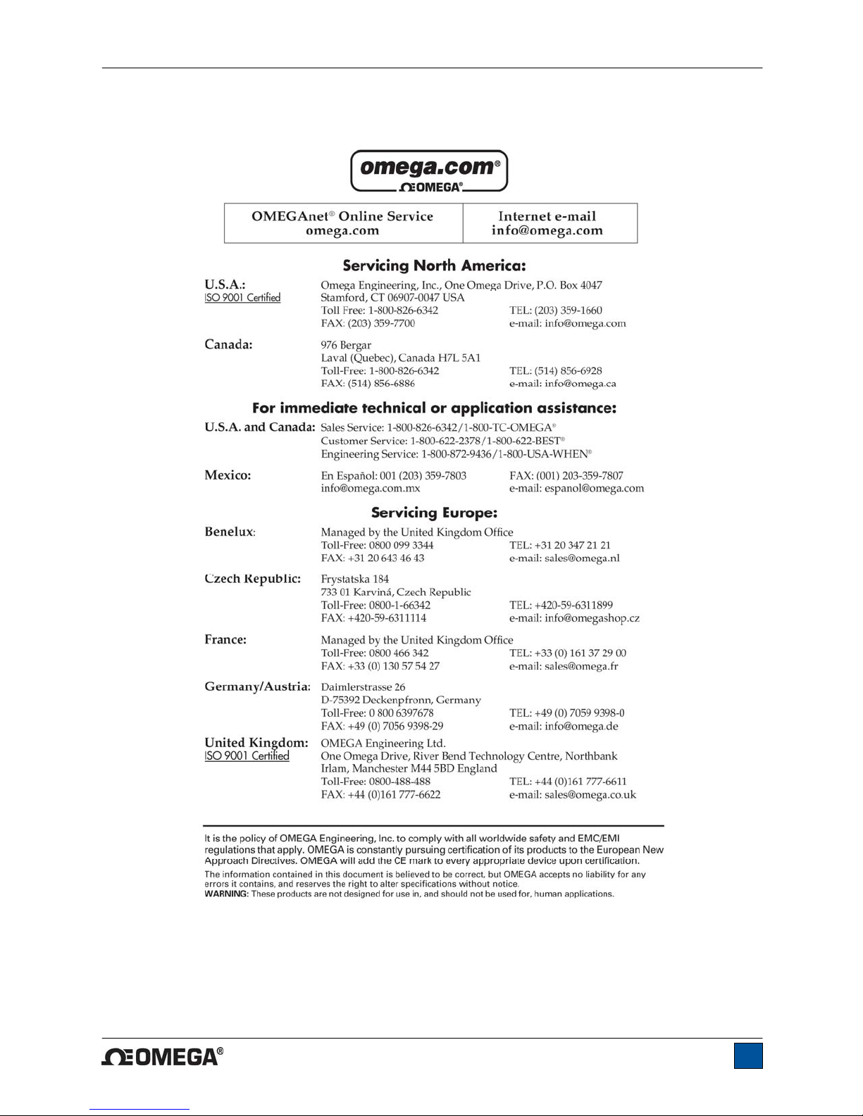
HHTQ35 Digital Torque Gauges User’s Guide
1
Page 3
HHTQ35 Digital Torque Gauges User’s Guide
Thank you…
Thank you for purchasing an Omega HHTQ35 digital torque gauge,
designed for handheld or test stand use.
With proper usage, we are confident that you will get many years of
great service with this product. Omega instruments are ruggedly
built for many years of service in laboratory and industrial
environments.
This User’s Guide provides setup, safety, and operation instructions.
Dimensions and specifications are also provided. For additional
information or answers to your questions, please do not hesitate to
contact us. Our technical support and engineering teams are eager
to assist you.
Before use, each person who is to use a HHTQ35 digital torque
gauge should be fully trained in appropriate operation and
safety procedures.
TABLE OF CONTENTS
OVERVIEW .........................................................3
POWER ...............................................................4
MECHANICAL SETUP .......................................5
HOME SCREEN AND CONTROLS ...................6
OPERATING MODES .........................................8
CHANGING THE UNITS .....................................9
DIGITAL FILTERS ..............................................9
SET POINT INDICATORS ..................................9
COMMUNICATIONS ........................................10
CALIBRATION .................................................14
OTHER SETTINGS ...........................................18
SPECIFICATIONS ............................................20
2
Page 4

HHTQ35 Digital Torque Gauges User’s Guide
1 OVERVIEW
1.1 List of included items
Qty. Part No. Description
1 12-1049 Carrying Case
1 08-1022 AC adapter body with US, EU, or UK prong
1 08-1026 Battery (inside the gauge)
1 - Certificate of calibration
1 09-1165 USB cable
1 - Resource CD (USB driver, user’s guide)
1.2 Safety / Proper Usage
Caution!
Note the torque gauge’s capacity before use and ensure that the capacity is not exceeded.
Producing a torque greater than 150% of the gauge’s capacity can damage the internal sensor. An
overload can occur whether the gauge is powered on or off.
Typical materials able to be tested include many manufactured items, such as springs, electronic
components, fasteners, caps, mechanical assemblies, and many others. Items that should not be used
with the gauge include potentially flammable substances or products, items that can shatter in an unsafe
manner, and any other components that can present an exceedingly hazardous situation when acted
upon by a force.
The following safety checks and procedures should be performed before and during o peration:
1. Never operate the gauge if there is any visible damage to the AC adapter or the gauge itself.
2. Ensure that the gauge is kept away from water or any other electrically conductive liquids at all
times.
3. The gauge should be serviced by a trained technician only. AC power must be disconne cted and
the gauge must be powered off before the housing is opened.
4. Always consider the characteristics of the sample being tested before initiating a test. A risk
assessment should be carried out beforehand to ensure that all safety measures have been
addressed and implemented.
5. Wear eye and face protection when testing, especially when testing brittle samples that have the
potential to shatter under force. Be aware of the dangers posed by potential energy that can
accumulate in the sample during testing. Extra bodily protection should be worn if a destructive
failure of a test sample is possible.
6. In certain applications, such as the testing of brittle samples that can shatter, or other applications
that could lead to a hazardous situation, it is strongly recommended that a machine guarding
system be employed to protect the operator and others in the vicinity from shards or debris.
7. When the gauge is not in use, ensure that the power is turned off.
3
Page 5
HHTQ35 Digital Torque Gauges User’s Guide
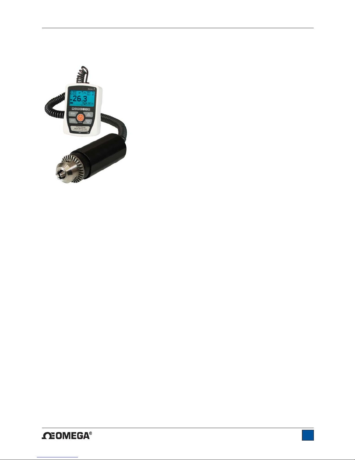
2 POWER
The HHTQ35 is powered either by an 8.4V NiMH rechargeable battery or by an AC adapter. Since these
batteries are subject to self discharge, it may be necessary to recharge the unit after a prolonged period
of storage. Plug the accompanying charger into the AC outlet and insert the charger plug into the
receptacle on the gauge (refer to the illustration below). The battery will fully charge in approximately 8
hours.
USB connector
Power input jack
Caution!
Do not use chargers or batteries other than supplied or instrument damage may occur.
If the AC adapter is plugged in, an icon appears in the lower left corner of the display, as follows:
If the AC adapter is not plugged in, battery power drainage is denoted in a five-step process:
1. When battery life is greater than 75%, the following indicator is present:
2. When battery life is between 50% and 75%, the following indicator is present:
3. When battery life is between 25% and 50%, the following indicator is present:
4. When battery life is less than 25%, the following indicator is present:
5. When battery life drops to approximately 2%, the indicator from step 4 will be flashing.
Several minutes after (timing depends on usage and whether the backli ght is turned on or
off), a message will appear, “BATTERY VOLTAGE TOO LOW. POWERING OFF”. A 4-tone
audio indicator will sound and the gauge will power off.
The gauge can be configured to automatically power off following a period of inactivity. Refer to the Other
Settings section for details.
If battery replacement is necessary, the battery may be accessed by loosening the two captive screws in
the rear half of the housing and separating the two halves of the housing.
4
Page 6
HHTQ35 Digital Torque Gauges User’s Guide
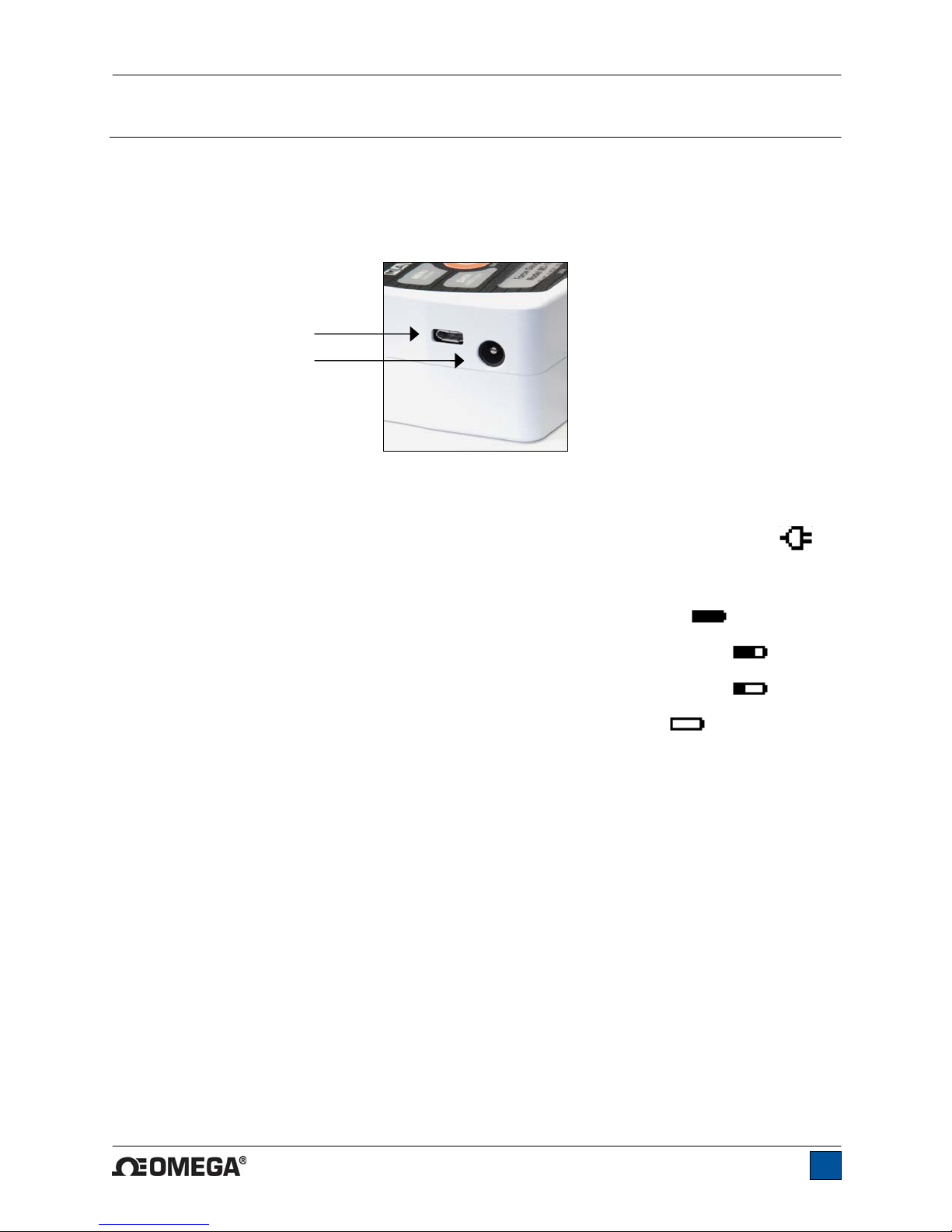
3 MECHANICAL SETUP
Fig. 3.1
Proper axial loading of HHTQ35 torque gauge.
3.1 Proper alignment
Load must be applied axially with respect to the sensor, as shown in Figure 3.1. If attachments are used,
ensure that the sample is acted upon axially with respect to the instrument. Side loading or off-center
loading can damage the instrument, whether power is turned on or off.
3.2 Mounting to a plate
The indicator portion of the gauge can be mounted to a plate with four thumb screws fastened into the
appropriate holes in the rear half of the housing.
The torque sensor portion of the gauge (shown in Figure 3.1) can be mounted to a stand, as required for
the application. Flat surfaces are provided to prevent rotation within a fixture.
Refer to the Dimensions section for detailed information.
5
Page 7
HHTQ35 Digital Torque Gauges User’s Guide
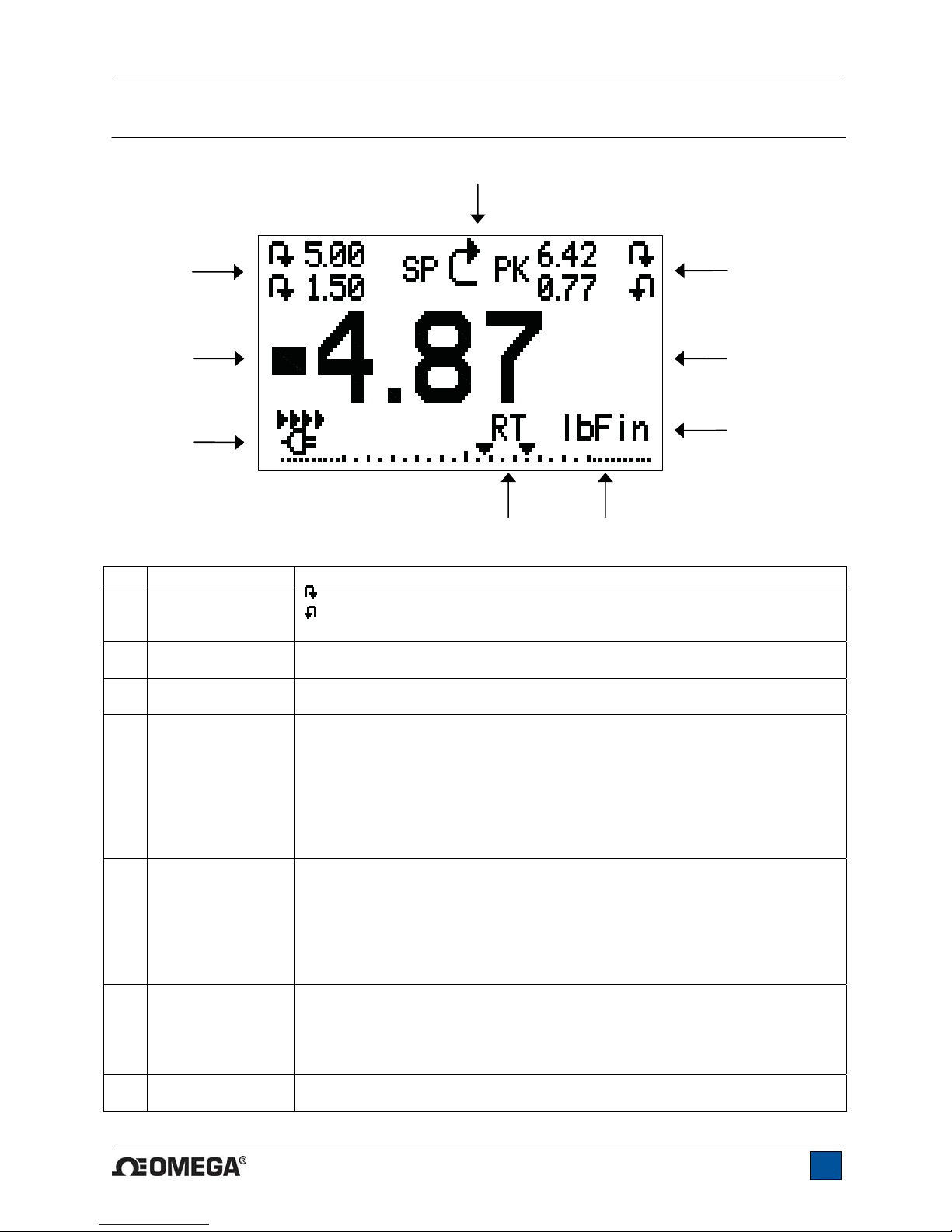
4 HOME SCREEN AND CONTROLS
4.1 Home Screen
9
No. Name Description
1 Measurement
2 Peaks
3 Primary reading
4 Load bar
5 Units
6 Mode
7 Battery / AC
8
7
direction
indicator
adapter indicator
– indicates clockwise direction
– indicates counter-clockwise direction
These indicators are used throughout the display and menu.
The maximum measured clockwise and counter-clockwise readings. These
readings are reset by pressing ZERO or by powering the gauge off and on.
The current displayed load reading. See Operating Modes section for
details.
Analog indicator to help identify when an overload condition is imminent. The
bar increases either to the right or to the left from the midpoint of the graph.
Increasing to the right indicates clockwise load, increasing to the left indicates
counter-clockwise load. If set points are enabled, triangular markers are
displayed for visual convenience. This indicator reflects the actual load, which
may not correspond to the primary reading (depends on operating mode).
The ZERO key does not reset the load bar. See Operating Modes section for
details.
The current measurement unit. Abbreviations are as follows:
lbFin – Pound-inch
ozFin – Ounce-inch
kgFmm – Kilogram-millimeter
Ncm – Newton-centimeter
Note: not all sensor models display all the above units. Refer to the capacity /
resolution table for details.
The current measurement mode. Abbreviations are as follows:
RT – Real Time
PCW – Peak Clockwise
PCCW – Peak Counter-clockwise
See Operating Modes section for details about each of these modes
Either the AC adapter icon or battery power icon will be shown, depending on
power conditions. Refer to the Power section for details.
1
2
3
4
56
6
Page 8
HHTQ35 Digital Torque Gauges User’s Guide
8 High / low limit
indicators
Correspond to the programmed set points. Indicator definitions are as follows:
– the displayed value is greater than the upper load limit
– the displayed value is between the load limits
– the displayed value is less than the lower load limit
9 Set points
The programmed load limit values. Typically used for pass/fail type testing.
One, two, or no indicators may be present, depending on the configuration
shown in the Set Points menu item.
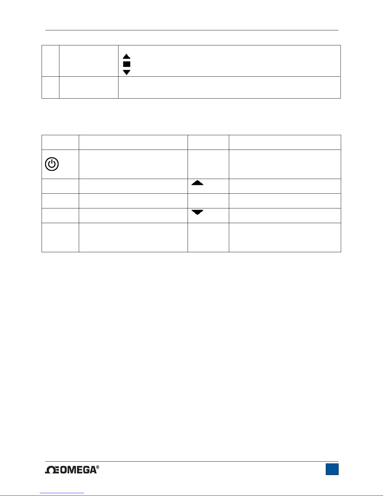
4.2 Controls
Primary
Label Primary Function
Powers the gauge on and off. Press
briefly to power on, press and hold
to power off. Active only when the
Secondary
Label Secondary Function
ENTER
Various uses, as described in the
following sections.
home screen is displayed.
ZERO
MENU
Zeroes the primary reading and
peaks.
Enters the main menu.
(UP)
ESCAPE
Navigates up through the menu and
sub-menus .
Reverts one step backwards through
the menu hierarchy.
MODE
DATA
Toggles between measurement
modes.
Transmits the current reading to an
external device via the USB port.
(DOWN)
DIRECTION
Navigates down through the menu
and sub-menus.
Toggles between clockwise and
counter-clockwise directions while
configuring set points and other menu
functions.
Note: Measurement units are configured through the menu. Refer to Section 6 for details.
7
Page 9

HHTQ35 Digital Torque Gauges User’s Guide
4.3 Menu navigation basics
Most of the gauge’s various functions and parameters are configured through the main menu. To access
the menu press MENU. Use the UP and DOWN keys to scroll through the items. The cu rrent selection is
denoted with clear text over a dark background. Press ENTER to select a menu item, then use UP and
DOWN again to scroll through the sub-menus. Press ENTER again to select the sub-menu item.
For parameters that may be either selected or deselected, press ENTER to toggle between selecting and
deselecting. An asterisk (*) to the left of the parameter label is used to indicate when the parameter has
been selected.
For parameters requiring the input of a numerical value, use the UP and DOWN keys to increment or
decrement the value. Press and hold either key to auto-increment at a gradually increasing rate. When
the desired value has been reached, press ENTER to save the change and revert back to the sub-menu
item, or press ESCAPE to revert back to the sub-menu item without saving. Press ESCAPE to revert one
step back in the menu hierarchy until back into normal operating mode.
Refer to the following sections for details about setting up particular functions an d parameters.
5 OPERATING MODES
Caution!
In any operating mode, if the capacity of the instrument has been exceeded by more than 110%,
the display will show “OVER” to indicate an overload. A continuous audible tone will be sounded
(if beeps are enabled) until the MENU key has been pressed or the load has been reduced to a
safe level.
Three operating modes are possible with the HHTQ35 torque gauge. To cycle between the modes, press
MODE while in the home screen.
5.1 Real time (RT)
The primary reading corresponds to the live measured reading.
5.2 Peak Clockwise (PCW)
The primary reading corresponds to the peak clockwise reading observed. If the actual load decreases
from the peak value, the peak will still be retained in the primary reading area of the display. Pressing
ZERO will reset the value.
5.3 Peak Counter-clockwise (PCCW)
Same as above, but for counter-clockwise readings.
8
Page 10

HHTQ35 Digital Torque Gauges User’s Guide
6 CHANGING THE UNITS
The HHTQ35 can display three different measurement units, depending on the model. To change the
unit, select Units from the menu. The display will list the available units, for example:
UNITS
* lbFin
kgFmm
Ncm
The gauge will always power on with the unit selected.
7 DIGITAL FILTERS
Digital filters are provided to help smooth out the readings in situations where there is mechanical
interference in the work area or test sample. These filters utilize the moving average technique in which
consecutive readings are pushed through a buffer and the displayed reading i s the average of the buffer
contents. By varying the length of the buffer, a variable smoothing effect can be achieved. The selection
of 1 will disable the filter since the average of a single value is the value itself.
To access digital filter settings, select Filters from the menu. The display will appear as follows:
DIGITAL FILTERS
(1 = Fastest)
Current Reading
8
Displayed Reading
1024
Two filters are available:
Current Reading – Applies to the peak capture rate of the instrument.
Displayed Reading – Applies to the primary reading on the display.
Available settings: 1,2,4,8,16,32,64,128,256,512,1024. It is recommended to keep the current reading
filter at its lowest value for best performance, and the displayed reading filter at its highest value for best
stability.
8 SET POINT INDICATORS
8.1 General Information
Set points are useful for tolerance checking (pass/fail). Two limits, high and low, are specified and stored
in the non-volatile memory of the instrument and the primary reading is compared to these limits.
8.2 Configuration
To configure set points, select Set Points from the menu. The screen will appear as follows:
9
Page 11

HHTQ35 Digital Torque Gauges User’s Guide
SET POINTS
Upper Disabled
* Upper Enabled
5.00
Lower Disabled
* Lower Enabled
3.50
Either one, two, or none of the set points may be enabled. To toggle between the clockwise and counterclockwise directions, press the DIRECTION key.
If two set points have been enabled, they are displayed in the upper left corner of the display. If only one
set point has been enabled, the word “OFF” will appear in place of the value. If no set points have been
enabled, the upper left corner of the display will be blank.
When set points are enabled, the following indicators are shown to the left of the primary reading:
Note: Set point indicators reference the displayed reading, not necessarily the current live load.
– the displayed value is greater than the upper
load limit (NO GO HIGH)
– the displayed value is between the limits (GO)
– the displayed value is less than the lower load
limit (NO GO LOW)
9 COMMUNICATIONS
Communication with the HHTQ35 is achieved through the micro USB port located along the left side of
the housing, as shown in the illustration in the Power section. Communication is possible only when the
gauge is in the main operating screen (i.e. not in a menu or configuration area). The current reading is
transmitted from the gauge when the DATA key is pressed.
9.1 Installing the USB driver
Caution!
It is recommended that the USB driver be installed before physically connecting the tester to the
PC with a USB cable.
1. Insert the Resource CD supplied with the gauge into the CD/DVD drive in the computer. Then,
navigate in Windows Explorer or My Computer to the following folder on the CD:
“Windows_XP_S2K3_Vista_7”.
2. Run the installer application “OmegaUSBInstaller.exe” by double-clicking it. When the program
launches, one of the following windows will appear, depending on the operating system:
10
Page 12

HHTQ35 Digital Torque Gauges User’s Guide
or
Click “Install”.
3. The next screen appears as follows:
or
Click “Install this driver software anyway” or “Continue Anyway”.
4. After installation completes the following screen may appear in non-Windows 7 operating systems.
Restart the computer before connecting an Omega USB device.
5. After Windows as restarted, plug in the device. The following will occur:
Windows 7 Operating Systems – When the Omega USB device has been plugged into a USB
port, the driver will automatically be found. When the driver installation is complete, a message
will appear as follows: “The Omega USB Device driver is now installed and ready to use”.
Non-Windows 7 Operating Systems – When the Omega USB device has been plugged into a
USB port, the following screen appears:
11
Page 13

HHTQ35 Digital Torque Gauges User’s Guide
Select “No, not this time”, then click “Next”.
6. The next screen appears as follows:
Select “Install the software automatically (Recommended)”, then click “Next”.
7. The next screen appears as follows:
12
Page 14

HHTQ35 Digital Torque Gauges User’s Guide
Click “Continue Anyway”.
8. The next, and final, screen appears as follows:
Click “Finish”. The Omega USB device is now installed and ready to use. The COM port number assigned
by Windows may be identified in Device Manager, or in the communication application being used.
9.2 Communication Settings
To set up communication settings, select USB Settings from the menu. The screen appears as follows:
USB SETTINGS
+ Baud Rate
+ Data Format
Communication settings are permanently set to the following:
Data Bits: 8
Stop Bits: 1
Parity: None
Other settings are configured as follows:
9.2.1 Baud Rate
Select the baud rate as required for the application. It must be set to the same value as the receiving
device.
9.2.2 Data Format
Select the desired data format. The screen appears as follows:
13
Page 15

HHTQ35 Digital Torque Gauges User’s Guide
DATA FORMAT
* Numeric + Units
Numeric Only
Invert Polarity
Omit Polarity
Selection Description
Numeric + Units Output format includes the value and unit of measure. Clockwise values have
positive polarity, counter-clockwise values have negative polarity.
Numeric Only Output format includes the value only. Polarity same as above.
Invert Polarity Clockwise values have negative polarity, counter-clockwi se values have positive
polarity. May be selected in addition to the Numeric + Units / Numeric Only
selection.
Omit Polarity Both directions are formatted with positive polarity. May be selected in addition to
the Numeric + Units / Numeric Only selection.
Individual data points may be transmitted by pressing DATA.
10 CALIBRATION
10.1 Initial Physical Setup
The sensor should be mounted vertically
equal to the full capacity of the instrument. Vertical orientation is preferable to avoid side loading, which
can affect the readings. Suitable certified calibration equipment is required, and caution should be taken
while handling such equipment.
10.2 Calibration Procedure
1. Select Calibration from the menu. The display will appear as follows:
CALIBRATION
ENTER # CAL POINTS
(1 TO 10)
CLOCKWISE:
5
COUNTER-CLOCKWISE:
5
The sensor can be calibrated at up to 10 points in each direction. Enter the number of calibration
points for each direction. At least one point must be selected for each direction.
Note: To achieve the accuracy specification of ±0.5% of full scale, it is recommended to calibrate
the sensor at 5 or more even increments in both the clockwise and counter-clockwi se directi ons.
For example, a sensor with capacity of 50 lbFin should be calibrated at 10, 20, 30, 40, and 50
lbFin loads in each direction.
2. To escape the Calibration menu at any time, press ESCAPE. The display will appear as follows:
to a test stand or fixture rugged enough to withstand a load
14
Page 16

HHTQ35 Digital Torque Gauges User’s Guide
CALIBRATION
NOT COMPLETE
CANCEL
EXIT W/O SAVING
Selecting “CANCEL” will revert back to the Calibration setup. Selecting “EXIT W/O SAVING” will
return to the menu without saving changes.
3. After the number of calibration points has been entered, press ENTER. The display will appear as
follows:
CALIBRATION
OFFSET
Place gauge
vertical
THEN PRESS ZERO
4. Place the torque sensor vertically in a fixture free from vibration, then press ZERO. The gauge
will calculate offsets, and the display will appear as follows:
CALIBRATION
OFFSET
Please wait…
CALIBRATION
OFFSET
Sen.Offset Adj.Passed
Ana.Offset Adj.Passed
Sen.Offset Adj.Failed
Ana.Offset Adj.Failed
CALIBRATION
OFFSET
5. The following screen appears after the offsets have been calculated:
CALIBRATION
CLOCKWISE
Attach necessary
weight fixtures.
THEN PRESS ENTER
Keep the sensor in a vertical position, as explained in Section 10.1. Attach weight fixtures
(brackets, hooks, etc), as required. Do not yet attach any weights or apply any calibration loads.
Then press ENTER.
If failed:
15
Page 17

HHTQ35 Digital Torque Gauges User’s Guide
6. The display will appear as follows:
CALIBRATION
CLOCKWISE
Optionally exercise
load cell a few times.
THEN PRESS ENTER
Optionally exercise the sensor several times (at full scale, if possible), then press ENTER.
7. The display will appear as follows:
CALIBRATION
CLOCKWISE
GAIN ADJUST
APPLY FULL SCALE LOAD
50.000 LBFIN +/-20%
THEN PRESS ENTER
Apply torque equal to the full scale of the instrument, then press ENTER.
8. After displaying “PLEASE WAIT…” the display will appear as follows:
CALIBRATION
CLOCKWISE
ENSURE NO LOAD
THEN PRESS ZERO
Remove the torque applied in Step 7, leave the fixtures in place, then press ZERO.
9. The display will appear as follows:
CALIBRATION
CLOCKWISE
APPLY LOAD
1 OF 5
ENTER LOAD:
10.000 LBFIN
THEN PRESS ENTER
Use the UP and DOWN keys to adjust the torque value as required. The torque values default to
even increments, as indicated by the previously entered number of data points described in Step
1. Then press ENTER.
Repeat the above step for the number of data points selected.
10. After all the clockwise calibration points have been completed, the display will appear as follows:
16
Page 18

HHTQ35 Digital Torque Gauges User’s Guide
CALIBRATION
CLOCKWISE COMPLETE
REVERSE DIRECTION
FOR CCW
Attach necessary
weight fixtures.
THEN PRESS ENTER
Press ENTER.
11. At the completion of the counter-clockwise calibration, the display will appear as follows:
CALIBRATION
COMPLETE
SAVE & EXIT
EXIT W/O SAVING
To save the calibration information, select “SAVE & EXIT”. To exit without saving the data select
“EXIT W/O SAVING”.
12. Any errors are reported by the following screens:
CALIBRATION
Units must be kgFmm.
PLEASE TRY AGAIN
PRESS ENTER
Displayed at the start of calibration if a disallowed unit is selected.
LOAD NOT STABLE
PLEASE TRY AGAIN
Ensure that the load is not swinging, oscillating, or vibrating in any manner. Then try again.
CALIBRATION
CLOCKWISE
LOAD TOO LOW
PLEASE TRY AGAIN
The calibration load does not match the set value.
17
Page 19

HHTQ35 Digital Torque Gauges User’s Guide
CALIBRATION
COUNTER-CLOCKWISE
LOAD TOO CLOSE
TO PREVIOUS
PLEASE TRY AGAIN
The entered calibration point is too close to the previous point.
11 OTHER SETTINGS
11.1 Automatic Shutoff
The gauge may be configured to automatically power off following a period of inactivity while on battery
power. Inactivity is defined as the absence of any key presses or load changes of 100 counts or less. To
access these settings, select Automatic Shutoff from the menu. The display will appear as follows:
AUTOMATIC SHUTOFF
* Disabled
Enabled
Set Minutes
5
Select Disabled to disable automatic shutoff. Select Enabled to enable it. The length of time of inactivity
is programmed in minutes via the Set Minutes parameter. Available settings: 5-30, in 5 minute
increments.
Note: If the AC adapter is plugged in, the gauge will ignore the Automatic Shutoff setting and remain
powered on until the POWER key is pressed.
11.2 Backlight
Several initial settings are available upon powering on the gauge. To access these settings, select
Backlight from the menu. The display will appear as follows:
BACKLIGHT
Off
On
* Auto
Set Minutes
1
Select Off for the backlight to be off upon powering on the gauge.
Select On for the backlight to be on upon powering on the gauge.
Select Auto for the backlight to be on upon powering on the gauge, but will shut off after a period of
inactivity (as defined in the Automatic Shutoff sub-section). The backlight will turn on again when activity
resumes. The length of time of inactivity is programmed in minutes via the Set Minutes parameter.
Available settings: 1-10, in 1 minute increments.
18
Page 20

HHTQ35 Digital Torque Gauges User’s Guide
Note: If the AC adapter is plugged in, the gauge will ignore these settings and keep the backlight on.
Selecting the On or Off setting in the Backlight menu will manually turn the backlight on or off as if the
Backlight key were pressed.
11.3 LCD Contrast
The contrast of the display may be adjusted. Select LCD Contrast from the menu. The screen will appear
as follows:
LCD CONTRAST
Set Contrast
10
Press ENTER to modify the contrast. Select a value from 0 to 25, 25 producing the most contrast.
11.4 Beeps
Audible tones can be enabled for all key presses and alerts, such as overload, set point value reached,
etc. The Set Point alert can be configured to be either a momentary tone or a continuous tone (until the
load is restored to a value between the set points). To configure the functions for which audibl e tones will
apply, select Beeps from the menu. The screen will appear as follows:
BEEPS
Keys
* Alerts
Set Points
* Momentary
Continuous
11.5 Initial Mode
This section is used to configure the initial mode upon powering on the gauge. To access this para m eter,
select Initial Mode from the menu. The screen will display the available modes. An example is as follows:
INITIAL MODE
* Real Time
Peak Clockwise
Peak Counter-clockwise
The default value is Real Time.
11.6 Information / Welcome Screen
The following screen is displayed at power up and can be accessed at any time by selecting Information
from the menu:
19
Page 21

HHTQ35 Digital Torque Gauges User’s Guide
Digital Torque Gauge
Series HHTQ35
Model No: HHTQ35-50
Serial No: 1234567
Version: 1.0
www.omega.com
12 SPECIFICATIONS
12.1 General
Accuracy:
Sampling rate:
Power:
Battery life:
Measurement units:
USB output:
Configurable
settings:
Safe overload:
Weight:
Included accessories:
Warranty:
12.2 Factory Settings
Parameter Setting
Set points
Upper Disabled (defaults to 80% of full scale, clockwise, when enabled)
Lower Disabled (defaults to 40% of full scale, clockwise, when enabled)
Filters
Current 8
Displayed 1024
Backlight Auto
Minutes 1
USB Output
Baud Rate 9,600
Data Format Numeric + units
Automatic Shutoff Enabled
Minutes 5
Beeps
Keys Enabled
Alerts Enabled
Set Points Momentary
LCD Contrast 10
Initial Mode Real Time
Units Depends on gauge model
±0.5% of full scale
2,000 Hz
AC or rechargeable battery. Low battery indicator appears when battery level is low, and
gauge powers off automatically when power reaches critical stage.
Backlight on:
Backlight off:
lbFin, ozFin, kgFmm, Ncm (depending on model)
Individual data point output by pressing DATA button. Configurable up to 115,200 baud.
Digital filters, USB output, set points, automatic shutoff, default units, default mode, key
tones, audio alarms, calibration
150% of full scale (display shows “OVER” at 110% and above)
1.8 lb [0.8 kg]
Carrying case, AC adapter, battery, USB cable, resource CD (USB driver, user’s guide),
NIST-traceable certificate of calibration
3 years (see individual statement for further details)
up to 7 hours of continuous use
up to 24 hours of continuous use
20
Page 22

HHTQ35 Digital Torque Gauges User’s Guide
12.3 Capacity & Resolution
Model ozFin lbFin kgFmm Ncm
HHTQ35-10Z 10 x 0.01 - 7 x 0.005 7 x 0.005
HHTQ35-20Z 20 x 0.02 - 14 x 0.01 14 x 0.01
HHTQ35-50Z 50 x 0.05 - 36 x 0.05 36 x 0.05
HHTQ35-12 192 x 0.2 12 x 0.01 - 135 x 0.1
HHTQ35-50 800 x 1 50 x 0.05 - 570 x 0.5
HHTQ35-100 1600 x 2 100 x 0.1 - 1150 x 1
12.4 Dimensions
IN [MM]
Ø 0.38 [9.5] MAX HHTQ35-50Z AND SMALLER
Ø 0.50 [12.7] MAX HHTQ35-12 AND LARGER
2.53 [64.3]
3.90 [99.1]
3.50 [88.9]
4.82 [122.4] HHTQ35-50Z AND SMALLER
5.19 [131.8] HHTQ35-12 AND LARGER
21
Page 23

HHTQ35 Digital Torque Gauges User’s Guide
22
Page 24

HHTQ35 Digital Torque Gauges User’s Guide
M-5086/0712
23
 Loading...