

Page 1
NIST
OMEGACOMENUSPDFMANUALS
omega.com
OMEGACOMENUSPDFMANUALS
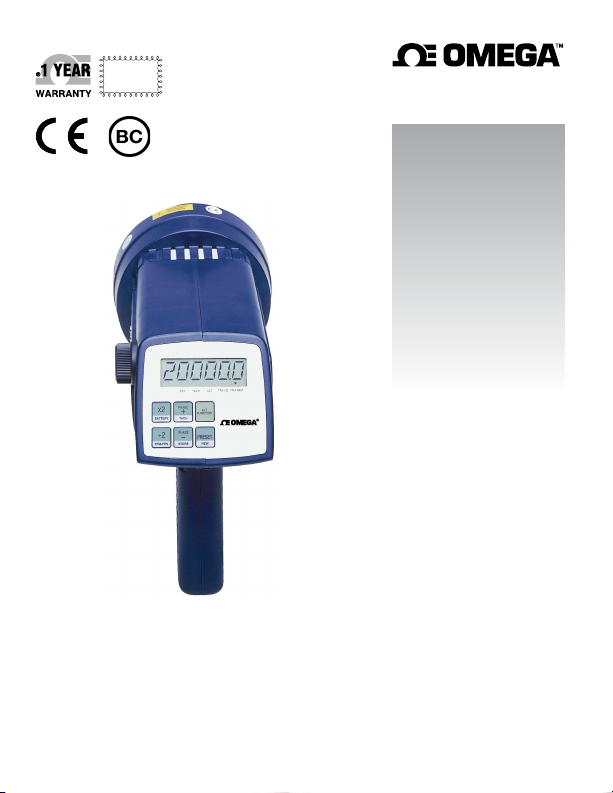
HHT31R and HHT32R
Deluxe Stroboscopes
Page 2

omega.com info@ omega.com
U.S.A.
Headquarters:
Servicing North America:
Omega Engineering, Inc.
Toll-Free: 1-800-826-6342 (USA & Canada only)
Customer Service: 1-800-622-2378 (USA & Canada only)
Engineering Service: 1-800-872-9436 (USA & Canada only)
Tel: (203) 359-1660
Fax: (203) 359-7700
e-mail: [email protected]
For Other Locations Visit omega.com/worldwide
The information contained in this document is believed to be correct, but OMEGA accepts no liability for any errors it contains, and reserves the right
to alter specifications without notice.
Page 3
Safeguards and Precautions
1. Read and follow all instructions in this manual carefully, and retain
this manual for future reference.
2. Do not use this instrument in any manner inconsistent with these
operating instructions or under any conditions that exceed the
environmental specifi cations stated.
3. Certain strobe frequencies can trigger epileptic seizures in those
prone to that type of attack.
4. Users should not stare directly at the light source.
5. Prolonged exposure to the light can cause headaches in some
people.
6. Objects viewed with this product may appear to be stationary when
in fact they are moving at high speeds. Always keep a safe distance
from moving machinery and do no touch the target.
7. There are lethal voltages present inside this product. Refer to
the section on Lamp Replacement before attempting to open this
product.
AC Stroboscopes that have three wire mains cable must have
the earth wire connected to a suitable Earth point.
8. Do not allow liquids or metallic objects to enter the ventilation holes
on the stroboscope as this may cause permanent damage and void
the warranty.
9. Do not allow cables extending from unit to come into contact with
rotating machinery, as serious damage to the equipment, or severe
personal injury or death may occur as a result.
Page 4

10. This instrument may not be safe for use in certain hazardous
environments, and serious personal injury or death could occur
as a result of improper use. Please refer to your facility’s safety
program for proper precautions.
11. The HHT32R contains Nickel Metal Hydride batteries which must be
disposed of in accordance with Federal, State, & Local Regulations.
Do not incinerate. Batteries should be shipped to a reclamation
facility for recovery of the metal and plastic components as the
proper method of waste management. Contact distributor for
appropriate product return procedures.
12. This instrument is not user serviceable. For technical assistance,
contact the sales organization from which you purchased the
product or Monarch Instrument directly.
In order to comply with EU Directive 2012/19/EU on Waste
Electrical and Electronic Equipment (WEEE): This product
may contain material which could be hazardous to human health
and the environment. DO NOT DISPOSE of this product as
unsorted municipal waste. This product needs to be RECYCLED
for more information. This product may be returnable to your distributor for
recycling - contact the distributor for details.
in accordance with local regulations, contact your local authorities
Page 5

TABLE OF CONTENTS
TABLE OF CONTENTS
1.0 OVERVIEW ..............................................................................1
1.1 Display Panel / Defi nition of Buttons ..........................1
2.0 PREPARATION FOR USE ......................................................3
2.1 Power .............................................................................3
2.2 Input / Output Connections ..........................................3
3.0 MENU ......................................................................................5
4.0 OPERATION ............................................................................6
4.1 Internal Mode - Standard Strobe Operation ................6
4.2 Internal Mode - TACH Frequency Generator...............9
4.3 External Input Mode ......................................................9
4.4 Tachometer Mode - External Input Required ............10
4.5 Power Up Features ......................................................10
5.0 USING THE STROBOSCOPE TO MEASURE RPM ............11
6.0 LAMP AND FUSE REPLACEMENT .....................................13
6.1 Lamp Replacement .....................................................13
6.2 Fuse Replacement ......................................................15
7.0 BATTERY POWERED MODELS ONLY ................................16
7.1 Low Battery Indication ................................................16
7.2 Charging the Batteries ................................................17
7.3 Battery Disposal ..........................................................18
8.0 SPECIFICATIONS .................................................................18
9.0 OPTIONS and ACCESSORIES / SENSORS ........................21
Page 6
1.0 OVERVIEW
All descriptions in this manual apply to both the battery powered (HHT32R)
and AC mains powered (HHT31R) digital stroboscopes except where noted.
1.1 Display Panel / Defi nition of Buttons
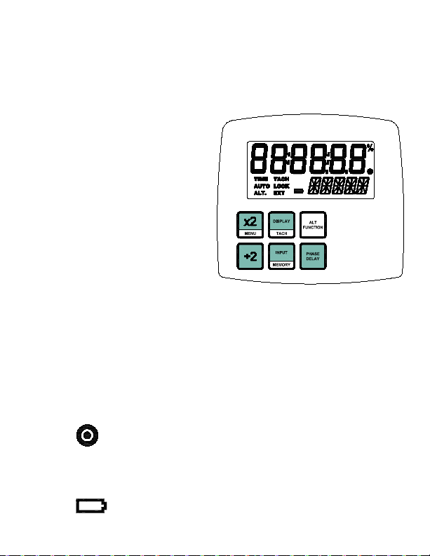
The display panel consists of
a backlighted liquid crystal
display with six numeric digits
on top and fi ve alphanumeric
digits on the bottom, which
indicate modes, fl ash rates, etc.
(see Figure 1).
A d d it i o n al i n f or m a t io n
displayed include:
TIME Unused
AUTO Unused
ALT. I n d ic at e s
alternate function of each button (lower section) and
knob will be used
TACH Tachometer Mode active (strobe won’t fl ash)
LOCK Unused
EXT External Input Mode active
On Target Indicator for Tachometer Mode and Remote
Sensor in External Mode
- - - - - Indicates input frequency exceeds the limit of the
stroboscope
(Batte ry Pow ered Model Only) Low Batter y
1
indication, see section 7.0
Figure 1 Display Panel
Page 7
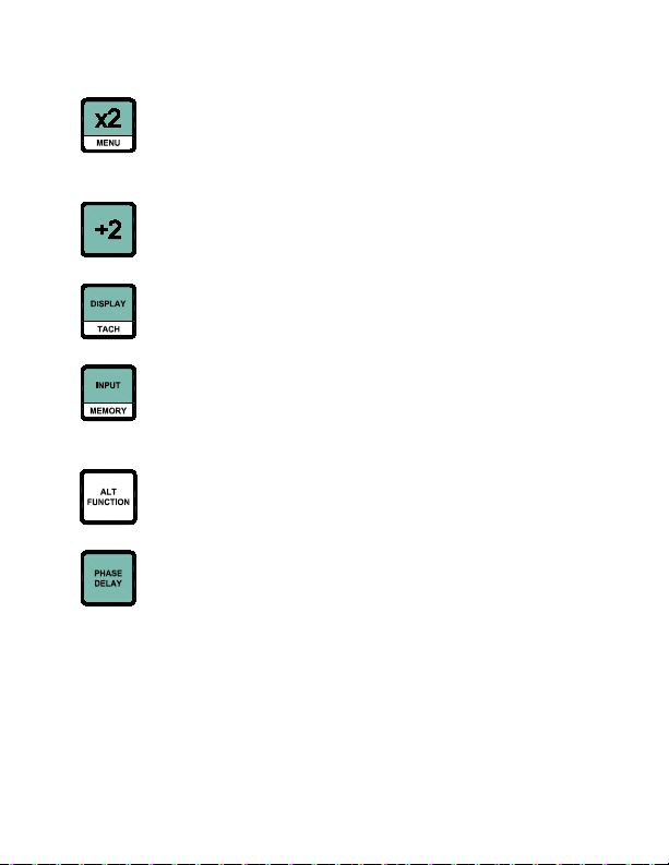
Below the display are six membrane buttons which control the operation
of the Stroboscope. They are:
Multiplies fl ash rate by 2 times
ALT Function - Starts Menu (See section 3.0)
Hold when powering up to show all segments, then Rev
# and display test
Divides fl ash rate by 2
Hold when powering up to reset factory defaults
Toggles display between RPM and RPS
ALT Function - Toggles Tach Mode (fl ashing) on/off
Manually toggles between Internal and External Modes
ALT Function - Memory - Reads and Stores 9 preset
fl ash rates
Activates Alternate Function for buttons (lower section)
and knob
In Internal Mode, toggles between normal fl ash rate
adjust and “phase” adjust
The ALT FUNCTION button toggles ALT. in the display. When ALT. is
displayed, the buttons will perform their secondary function listed in the
lower section of each button. It also changes how the tuning knob works.
2
Page 8
2.0 PREPARATION FOR USE
The Strobe may be hand held or mounted on a tripod or other user supplied
bracket using the ¼-20 UNC bushing at the base of the handle.
2.1 Power
The AC powered strobe must have its power cord plugged into an AC
outlet (115Vac or 230Vac).
The battery powered strobe has internal rechargeable batteries. The unit
should be charged before use (see section 7.0). The actual operating time
of the stroboscope depends on the fl ash rate and duty cycle of operation.
Slower fl ash rates (below 4,000 FPM) increase the operating time. Note
that the strobe will not operate from the recharger supplied with the unit.
2.2 Input / Output Connections
The strobe has input and output jacks on the left side of the stroboscope.
These can be used for external triggering or synchronization (daisy
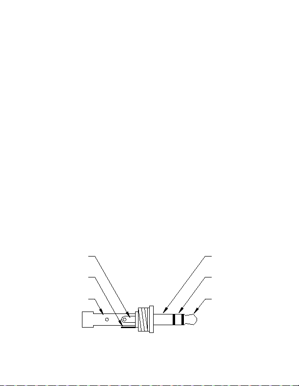
chaining two or more strobes). These jacks accept 1/8” (3.5mm) phone
plugs (input - stereo, output - mono). The input and output are TTL
compatible. See Figures 2 and 3 for connector connection detail.
Signal Input
+6V Out to
Sensor
Common
(GND)
Common
(GND)
+6V Out to
Sensor
Signal Input
Figure 2 Input Connector Detail (Stereo plug)
3
Page 9
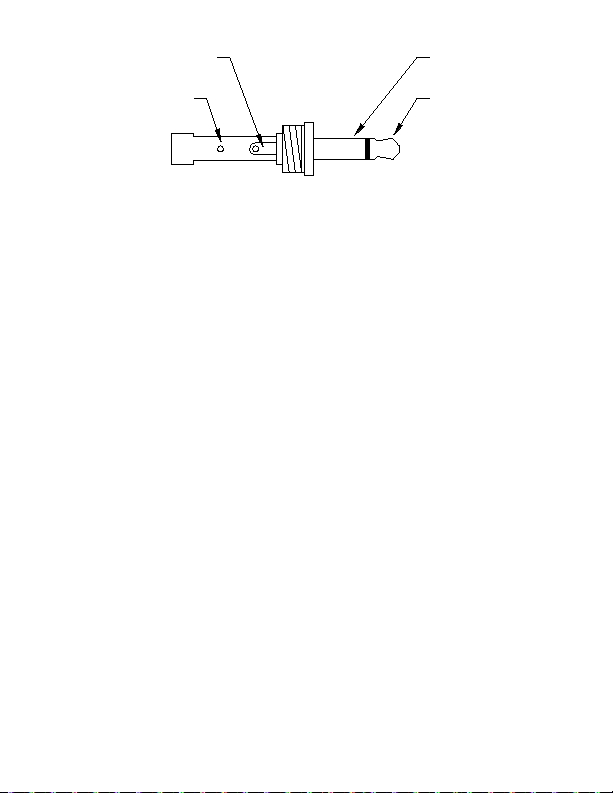
Pulse Output
from Strobe
Common
(GND)
Common
(GND)
Pulse Output
from Strobe
Figure 3 Output Connector Detail (Mono plug)
The input jack (p pointing into socket) enables an external signal to
trigger the strobe. Inserting a plug into the input jack will automatically
put the strobe into the External Input Mode. The INPUT button can be
used to toggle between Enternal Input Mode and Internal Mode. When
the plug is removed, the strobe will be put back into the Internal Mode.
The polarity of the input pulse can be set in the MENU options.
With no external input, the output jack (q pointing away from socket)
provides a TTL compatible pulse from the strobe’s internal oscillator.
If an external input is applied, the output pulse is in sync with the input
pulse. This output pulse may be used to trigger a second stroboscope
synchronously to illuminate larger areas. Many strobes can be “daisy
chained”. The output jack of one strobe is connected to the input jack of
the next strobe causing all the strobes to fl ash together and be controlled
by the fi rst strobe in the chain. The polarity of the output pulse can be
set in the MENU options.
4
Page 10

3.0 MENU
The strobe has a Menu which allows the user to select settings such as number
of decimal places, backlight on or off and positive or negative edge for input
and output signal.
To enter the MENU:
1. Press the ALT FUNCTION button and then the MENU button.
2. SETUP and the menu option will be displayed.
3. Turn the tuning knob to cycle through the main menu options.
4. Once the desired menu option is displayed, press the MENU button to
select it. Press any other button to cancel.
5. Turn the tuning knob to edit the menu option setting.
6. Press the MENU button to save your changes. Press any other button
to cancel.
7. Press any button other than MENU to exit the Main Menu.
8. DONE will be displayed.
Below is a list of the menu items:
DECPT - Decimal Point (none, 1 or 2)
BLITE - Backlight (Yes=On or No=Off)
INPUT - Positive (pos) or Negative (neg) Edge for Input Signal
OUTPT - Positive (pos) or Negative (neg) Edge for Output Signal
5
Page 11

4.0 OPERATION
To turn on the stroboscope, depress and hold the trigger. The trigger may
be locked in position using the side locking button. To lock the stroboscope
on, depress the trigger as far as it will go and then press the locking button.
Once the locking button is set you may release the trigger and the trigger
will be held in place. To unlock the stroboscope, simply depress the trigger
and then release.
NOTE: Unit must power down completely (OFF will be displayed and then
disappear) before unit will power on again. This is normal operation.
There are three major operating modes for the Strobe. These are Internal,
External Input and Charging (Battery powered model only). In the Internal
Mode, the knob adjusts the fl ash rate. In the External Input Mode, an
external signal is used to trigger the fl ash and the knob has no effect. The
Charging Mode (Battery powered model only) is when the strobe has the
battery recharger plugged into it. The strobe will continuously display the
state of the battery charge while being recharged.
4.1 Internal Mode - Standard Strobe Operation
In the Internal Mode the stroboscope generates it’s own signals and
functions like a tunable stroboscope. The strobe is in the Internal Mode
when nothing is plugged into the input jack or when manually set using
the INPUT button.
To change the fl ash rate:
With the power on, turn the knob counter clockwise to increase the fl ash
rate and clockwise to decrease it. The knob is velocity sensitive. Turn
the knob slowly to have each “click” is equal to 0.01 FPM. Turning the
knob more quickly will adjust the FPM by larger steps. When adjusting
fl ash rate, quickly turn the knob (or use the x2 or ÷2 buttons) to coarsely
change the FPM. Then slowly turn the knob for fi ne adjustments.
6
Page 12

NOTE: There are maximum and minimum values in each mode
beyond which you cannot adjust. If you are adjusting the
rate and you reach a value which on the next increment would
exceed the maximum fl ash rate, the display will not increment.
The same is true if you try to adjust the fl ash rate below the
minimum fl ash rate.
To multiply or divide the current fl ash rate by 2:
In addition to the knob, there are two buttons on the display panel marked
x2 and ÷2. This enables the user to instantly double or halve the reading
on the display to the maximum or minimum values allowed. This feature
is useful for checking harmonics in the internal fl ashing mode.
Alternate Knob Function (multiple by 2, 3, 4, 5, etc.)
The tuning knob functions differently when ALT. is displayed. The
current fl ash rate is used as an adder. The knob will add (counter
clockwise) or subtract (clockwise) that initial fl ash rate for each “click”
the knob is turned. This in effect allows the user to multiply the initial
fl ash rate by 2, 3, 4, 5, etc up to the maximum fl ash rate. This is very
helpful on fan blades. Using this feature, one can superimpose the
blades on top of each other and check for blade tracking, bent blades,
lead and lag tests, etc.
For example: A 3 bladed fan is spinning at 3600 RPM. The strobe is
fl ashing at 3600 FPM. Press the ALT FUNCTION button to display
ALT. Then turn the knob counter clockwise 2 clicks. The strobe will
now fl ash at 10,800 FPM (effectively 3600 times 3). The fans blades
will be all superimposed on each other. One can now see if the blades
are out of alignment, bent, etc. by viewing the blades from the front or
viewing from the side edge of the blades.
7
Page 13

To select a fl ash rate from a Preset (memory) location:
1. Press the ALT FUNCTION button and then the MEMORY button.
2. READ will be displayed.
3. Turn the tuning knob to cycle through the preset fl ash rates.
4. Once the desired fl ash rate is displayed, press the MEMORY button
to select it. Press any other button to cancel.
5. DONE will be displayed.
To store the current fl ash rate in a Preset (memory) location:
1. Press the ALT FUNCTION button and then the MEMORY button.
2. READ will be displayed.
3. Do NOT turn the knob and press the MEMORY button again.
4. STORE will be displayed.
5. Turn the tuning knob to cycle through the memory locations.
6. Once the desired memory location is displayed, press the
MEMORY button to store the current fl ash rate in that location.
Press any other button to cancel.
7. DONE will be displayed.
Internal “Phase” Delay
Once the fl ash rate has been adjusted to give a stopped motion image,
the PHASE DELAY button may be used with the knob to increase or
decrease the phase of the reference mark location. Use the PHASE
DELAY button and knob to bring a reference mark, such as a key way,
into your line of sight.
To adjust the “Phase” Delay:
1. Press the PHASE DELAY button.
2. PHASE will be displayed on the bottom line and the current fl ash
rate will be displayed on the top line.
8
Page 14

3. Turn the tuning knob to adjust the location (phase) of the reference
mark.
4. Press the PHASE DELAY button again to turn the “Phase” Delay
mode off.
4.2 Internal Mode - TACH Frequency Generator
In the Internal Mode, the strobe can be used as a frequency generator
(outputting TTL pulses) without having the strobe fl ash. The pulse
output will still occur at the fl ash rate; the strobe is just not fl ashing.
To stop fl ashing:
Press the ALT FUNCTION button and then the TACH button. The
TACH icon will be displayed.
To start fl ashing again:
Press the ALT FUNCTION button and then the TACH button. The
TACH icon will go away and the strobe will start fl ashing again.
4.3 External Input Mode
In the External Input Mode the user can’t make any flash rate
adjustments. The fl ash rate is a function of the input signal. This mode
is used to synchronize the fl ash to an external event (for example, from
an optical sensor) to stop or freeze motion. The fl ash will be triggered on
the rising or falling edge (menu selectable) of the external input pulse.
The strobe is in the External Input Mode whenever there is a plug in
the input jack. When the strobe is in the External Input Mode, EXT
will be displayed.
9
Page 15

4.4 Tachometer Mode - External Input Required
When an external input is supplied to the unit and the strobe is put in the
Tachometer Mode, the unit will read the signal from the external input
(sensor) and display the reading on the LCD display without fl ashing
the lamp. The strobe will not fl ash in the Tachometer Mode.
To enter the External Tachometer Mode:
1. Plug an external input into the unit.
2. Press the ALT FUNCTION button and then the TACH button. The
TACH icon will be displayed.
NOTE: If the external input signal exceeds the maximum fl ash rate,
the strobe will go into the Tachometer Mode automatically.
To exit the External Tachometer Mode:
1. Press the ALT FUNCTION button and then the TACH button. The
TACH icon will go away.
2. The unit will remain in the External Input Mode unless the INPUT
button is pressed to change the mode.
4.5 Power Up Features
When the strobe is powered up it will remember the last settings.
Press and hold the x2/MENU button, then turn on the strobe by
depressing the trigger switch. This will turn on all the display segments
for two seconds or until you release the button. It will then show the
software revision, “REV x.x” and then go through a display diagnostic.
Press and hold the ÷2 button, then turn on the strobe by depressing
the trigger switch. This will restore the factory programmed presets.
10
Page 16

5.0 USING THE STROBOSCOPE TO MEASURE
RPM
The primary use for a stroboscope is to stop motion for diagnostic inspection
purposes. However the stroboscope can be used to measure speed (in RPM
/ RPS). In order to do this several factors need to be considered. First, the
object being measured should be visible for all 360° of rotation (e.g. The
end of a shaft). Second, the object should have some unique part on it, like a
bolt, key way or imperfection to use as a reference point. If the object being
viewed is perfectly symmetrical, then the user needs to mark the object with
a piece of tape or paint in a single location to be used as a reference point.
Look only at the reference point.
If the speed of rotation is within the range of the stroboscope, start at the
highest fl ash rate and adjust the fl ash rate down. At some point you will stop
the motion with only a single reference point of the object in view. Note that
at a fl ash rate twice the actual speed of the image you will see two images
(reference points). As you approach the correct speed you may see three,
four or more images at harmonics of the actual speed. The fi rst SINGLE
image you see is the true speed. To confi rm the true speed, note the reading
and adjust the stroboscope to exactly half this reading, or just press the ÷2
button. You should again see a single image (which may be phase shifted
with respect to the fi rst image seen).
For example, when viewing a shaft with a single key way you will see one
stationary image of the key way at the actual speed and at 1/2,1/3,1/4, etc, of
the actual speed. You will see 2 images of the key way at 2 times the actual
speed, 3 key way at 3 times, etc. The Flashes Per Minute (FPM) equals
the shaft’s Revolutions Per Minute (RPM) at the highest fl ash rate that
gives only one stationary image of the key way.
11
Page 17

Stopped Image 1/4 times 1/2 times 1 time 2 times 3 times 4 times
Flash Rate (FPM) 1250 2500 5000 10000 15000 20000
Example: Object Rotating at 5000 RPM
If the speed is outside the full scale range of the stroboscope (20,000 FPM),
it can be measured using the method of harmonics and multipoint calculation.
Start at the highest fl ash rate and adjust the fl ash rate down. You will encounter
multiple images so be aware of these. Note the fl ash rate of the fi rst SINGLE
image you encounter, call this speed “A”. Continue decreasing the fl ash
rate until you encounter a second SINGLE image. Note this speed as “B”.
Continue decreasing the speed until you reach a third SINGLE image at
speed “C”.
For a two point calculation the actual speed is given by:
RPM = AB/(A-B)
For a three point calculation:
RPM = 2XY(X+Y)/(X-Y)2 where
X = (A-B) and
Y = (B-C)
If a Remote Optical Sensor or Magnetic Sensor is used to sense one pulse per
revolution (External mode), the readout will display directly in RPM (FPM)
without any adjustment required.
In instances when you can shut down the device and install a piece of refl ective
tape, then an optical tachometer is easier to use for RPM measurement.
Stroboscopes must be used when you can’t shut down the device. The
human eye is not easily tricked into seeing a stopped image by a stroboscope
when the fl ash rate is slower than 300 FPM. Therefore, stroboscopes are just
about impossible to use below 300 FPM for inspection or to measure RPM.
12
Page 18

6.0 LAMP AND FUSE REPLACEMENT
6.1 Lamp Replacement
WARNING: Before attempting to remove the lamp, make
sure the stroboscope is turned off and any
mains cord is removed from the AC outlet. Allow
the lamp to cool waiting at least 5 minutes.
The stroboscope is designed to discharge the internal high voltages
within 30 seconds. However, caution should be exercised when replacing
the lamp.
The lamp can be replaced by using just a pocket screwdriver. It is not
necessary to remove any screws to replace the lamp.
To change the lamp:
1. Push apart the two tabs on the side of the refl ector housing and
remove the lens using a small screwdriver to help pry one tab and
lift the lens. Take care not to pry the tab any more than is necessary
to free the lens. The refl ector is held in place by the front lens and
will come loose, but it is not necessary to remove the refl ector.
2. Hold the lamp with a cloth between your forefi nger and thumb and
rock it back and forth gently while pulling out. Do not attempt to
rotate the lamp. The lamp is socketed and will come out easily
when pulled straight out.
WARNING: Do NOT touch the new lamp with bare fi ngers.
3. The lamps are polarized and must be put into the socket matching
polarity. Using a lint free cloth, match up the red dot on the
plug with the red dot on the socket and gently rock the lamp
13
Page 19
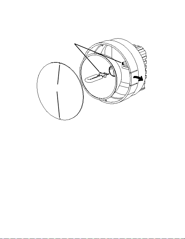
while pushing it into place (see Figure 4). Make sure the lamp is
in straight and centered in the refl ector hole.
CAUTION: Do NOT allow the refl ector to contact the lamp.
Red Dots
Notches
Figure 4 Lamp Replacement
4. Reinstall the refl ector and then position the front lens in place
matching up the notches on the lens with the two small tabs on
the housing to prevent lens rotation (see Figure 4). Push the tabs
on the front rim outward and press the lens into place.
14
Page 20

6.2 Fuse Replacement
Under normal operating conditions, the fuse within the stroboscope
should never blow. Examples of abnormal operating conditions would
be foreign materials entering the strobe, such as water, pulp, ink, etc.
The AC Powered stroboscope has a replaceable fuse inside the unit,
which may be accessed by removing the lens and refl ector - refer to
Figure 4. If the fuse needs to be replaced, replace only with a fuse of
the same type and value: Fast Blow - 750mA, 2AG.
WARNING: Before attempting to replace the fuse, make sure
the stroboscope is turned off and any mains
cord is removed from the AC outlet. Allow the
lamp to cool waiting at least 5 minutes.
The Battery Powered stroboscope has a resettable fuse, which will reset
once conditions are normal again.
15
Page 21

7.0 BATTERY POWERED MODELS ONLY
The HHT32R is fi tted with rechargeable NiMH (Nickel Metal Hydride)
batteries. These batteries contain fewer toxic metals than NiCd (Nickel
Cadmium) and are currently classifi ed “environmentally friendly”. They
also have 30% more capacity than NiCd batteries of the same size.
Like NiCds, NiMH batteries are prone to self-discharge - 10 to 15% of
charge is lost in the fi rst 24 hours then continues at a rate of 0.5 to 1% per
day. For maximum performance, charge the batteries just prior to use.
When not in use, the batteries should be charged at least every three months,
otherwise the battery capacity will be reduced or the batteries may become
unusable.
Charge the batteries before use and allow 3-5 cycles of charging and
discharging for batteries to reach full capacity.
The enclosure contains control electronics to properly and safely charge
the batteries. Never remove the batteries from the enclosure and attempt
to charge externally. Always use the charger supplied (HHT32R-URC).
7.1 Low Battery Indication
When the batteries are charged, there will be no battery indication. When
the batteries are low, the Low Battery icon will blink in the display. The
strobe may still be used for a short time.
Low Battery Icon = Outline blinking (very little time left)
The strobe has a protection feature that prevents the strobe from
operating if the battery voltage is too low. This condition is indicated
by no fl ash and the display shows “LO BAT”. At this time the batteries
must be recharged. Remember to release the trigger switch.
16
Page 22

7.2 Charging the Batteries
The unit may be recharged at any time. You do not need to wait until
the low battery condition is indicated.
To charge the battery powered strobe with the recharger:
1. Release the trigger so the strobe is off.
2. Plug the recharger cable into the recharger socket (located below
the display panel behind the handle).
3. Plug the recharger into an AC mains wall outlet (115/230 Vac).
CAUTION: Use of rechargers other than the one supplied
(HHT32R-URC) will damage the stroboscope
and void the warranty.
When the recharger plug is inserted into the recharger jack, the strobe
will go into the Charging Mode. Make sure the trigger switch is not
depressed. The strobe will not do anything else when charging (e.g. it
will not fl ash and the buttons have no function).
When charging, the strobe will indicate CHRGE in the bottom right of the
display. The recharger will fast charge the batteries for about 4-5 hours
and then trickle charge the batteries.
Allow the recharger to charge the batteries until the display shows DONE
for peak battery life performance. If the batteries are not charged to
100% regularly, the batteries will lose capacity.
17
Page 23

7.3 Battery Disposal
Prior to disposing of the battery-powered strobe, the user must remove
the Nickel-Metal Hydride batteries. To do this, remove the lens, refl ector
and lamp as detailed in the Lamp Replacement section. This will expose
four (4) screws that must be removed so the refl ector housing can be
dismantled. There are four (4) additional screws in the case half opposite
the input and output jacks that must be removed. The case halves can
now be separated, exposing the batteries. Unplug the batteries from
the circuit board. The batteries should be sent to a recycling center or
returned to the factory. The rest of the parts may now be disposed of.
8.0 SPECIFICATIONS
Internal Mode:
Flash Range 30 - 20,000 FPM (Flashes Per Minute)
Flash Rate Accuracy 0.004% of setting or ± last digit
Flash Rate Resolution 0.01 to 1 FPM (menu selectable), 0.1 FPM
max resolution above 9,999.99 FPM
Display Update Rate Instantaneous
External Modes:
Flash Range and Display same as internal mode - External fl ash rates
to 0 are acceptable
Tachometer Measurements 5 to 250,000 RPM
Accuracy: ±0.001% of reading or ± last digit
Display Update Rate 0.5 second typical
External Input TTL Compatible (24V pk max), 500 nanosec
min pulse width,
Positive or Negative edge triggered (menu
selectable)
18
Page 24

Output Pulse 40 µsec positive/negative pulse (menu selectable),
3.3 Vdc typical
Note: HHT31R – Input/Output connectors
isolated from AC power
Time Base Ultra Stable Crystal Oscillator
Display LCD display with 6 numeric 0.506 inch [12.85
mm] high digits and
5 alphanumeric 0.282 inch [7.17 mm] high digits
Indicators Battery level, On Target, ALT, TACH, and EXT
icons
Knob Adjustment Digital Rotary switch with 36 detents per
revolution; velocity sensitive
Memory Last setting before power down is remembered
and restored on next power up. 9 user settable
fl ash rates.
Flash Duration 10-25 microseconds (auto adjust with fl ash rate)
Flash Tube (Lamp) Life 100 million fl ashes
This product is designed to be safe for indoor use under the following
conditions (per IEC61010-1).
Operating Temperature 32-104 ºF [0-40 °C]
NOTE: Safety thermal feature will set unit into TACH Mode (stops
fl ashing) in the event of internal overheating.
Humidity Maximum relative humidity 80% for temperature up
to 88 °F [31 °C] decreasing linearly to 50% relative
humidity at 104 °F [40 °C]
Compliance: CE compliant. Low Voltage Directive (LVD) 2014/35/EU
Electr omagnet ic Com patibil ity Directive (EMC)
2014/30/EU
Restriction of Hazardous Substances (RoHS) Directive
2011/65/EU
19
Page 25
HHT32R Specifi c:
Trigger to Flash Delay 5 µsec typical
Input Power Battery powered: Internal Rechargeable Batteries
6 Vdc, External AC recharger (100 Vac to 240 Vac,
50/60 Hz)
Light Output Average: 13 Watts typical > 4000 FPM
Instantaneous (per fl ash): 230 mJoule typical to
4000 FPM
Run Time 2 hours typical at 1800 FPM, and over 1 hour at 6000
FPM with fully charged batteries
Charge Time 4-5 hours typical with HHT32R-URC
Weight 1.875 lbs [0.8505 kg] including batteries
Energy Effi ciency HHT32R units with Firmware Revision 1.43 and
higher are compliant with the U.S. Department of
Energy’s energy conservation standards specifi ed in
the Code of Federal Regulations 10 CFR 430.32(z).
HHT31R Specifi c:
Trigger to Flash Delay 5 µsec typical
Input Power AC powered: 115 Vac OR 230 Vac, 35VA (as ordered)
Light Output Average Power: 15.5 Watts typical > 4000 FPM
Instantaneous (per fl ash): 230 mJoule typical to
4000 FPM
Run Time Continuous within temperature limitations. Vents
must not be restricted. Unit must be horizontal.
Weight 1.55 lbs [0.70 kg]
Product specifi cations subject to change without notice.
Manufactured in an ISO9001 facility.
20
Page 26
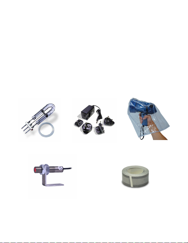
9.0 OPTIONS AND ACCESSORIES / SENSORS
HHT32-LAMP Digital Stroboscope replacement lamp
HHT32R-URC Universal Recharger, 115/230 Vac with USA, U.K., AUS,
Euro Adapter Plugs for Battery Powered Strobe
HHT32-SPC Splash proof Protective Cover for Battery Powered Strobe
ONLY
HHT20-ROS Remote Optical Sensor with 8 foot [2.5 m] cable for
triggering strobe
HHT-RT-5 Refl ective tape - 5 foot [1.5 m] roll, 0.5 inch [12.7 mm] wide
HHT32-LAMP HHT32R-URC HHT32-SPC
HHT20-ROS HHT-RT-5
21
Page 27

OMEGA’s policy is to make running changes, not model changes, whenever an improvement is possible. This affords
our customers the latest in technology and engineering.
OMEGA is a trademark of OMEGA ENGINEERING, INC.
© Copyright 2019 OMEGA ENGINEERING, INC. All rights reserved. This document may not be copied, photocopied,
reproduced, translated, or reduced to any electronic medium or machine-readable form, in whole or in part, without the
prior written consent of OMEGA ENGINEERING, INC.
FOR WARRANTY RETURNS, please have the
following information available BEFORE
contacting OMEGA:
1. Purchase Order number under which the
product was PURCHASED,
2. Model and serial number of the product under
warranty, and
3. Repair instructions and/or specific problems
relative to the product.
FOR NON-WARRANTY REPAIRS,
consult OMEGA
for current repair charges. Have the following
information available BEFORE contacting OMEGA:
1. Purchase Order number to cover the COST
of the repair,
2. Model and serial number of the product, and
3. Repair instructions and/or specific problems
relative to the product.
RETURN REQUESTS/INQUIRIES
Direc t all warran ty and repair request s/inqu iries to the OMEGA Custome r Service Departm ent.
BEFORE RETURNING ANY PRODUCT(S) TO OMEGA, PURCHASER MUST OBTAIN AN AUTHORIZED
RETURN (AR) NUMBER FROM OMEGA’S CUSTOMER SERVICE DEPARTMENT (IN ORDER TO AVOID
PROCESSING DELAYS). The assigned AR number should then be marked on the outside of the return
package and on any correspondence.
The purchaser is responsible for shipping charges, freight, insurance and proper packaging to prevent
breakage in transit.
WARRANTY/DISCLAIMER
OMEGA ENGINEERING, INC. warrants this unit to be free of defects in materials and workmanship
for a period of 13 months from date of purchase. OMEGA’s WARRANTY adds an additional one (1)
month grace period to the normal one (1) year product warranty to cover handling and shipping
time. This ensures that OMEGA’s customers receive maximum coverage on each product.
If the unit malfunctions, it must be returned to the factory for evaluation. OMEGA’s Customer Service
Department will issue an Authorized Return (AR) number immediately upon phone or written request.
Upon examination by OMEGA, if the unit is found to be defective, it will be repaired or replaced at no
charge. OMEGA’s WARRANTY does not apply to defects resulting from any action of the purchaser,
including but not limited to mishandlin g, improper interfacing, operation outside of design limits,
improper repair, or unauthorized modification. This WARRANTY is VOID if the unit shows evidence of
ha vi ng be en ta mpe re d wi th o r s ho ws ev id en ce of h av ing b ee n da ma ged a s a
re sul t of e xc ess ive c orr os ion ; or c urr en t, h eat , mo is tu re o r vi bra ti on ; im pro per
sp ec ifi ca ti on ; m isa pp li ca ti on; mi su se or o th er op er ati ng c on dit io ns ou ts id e o f
OM EGA’ s co ntr ol. Com pon ents in wh ich wea r i s no t wa rra nt ed , i ncl ude but ar e no t
limited to contact points, fuses, and triacs.
OMEGA is pleased to offer suggestion s on the use of it s various product s. Howeve r,
OM EGA n e it h er a s su m es r es pon sib i li t y fo r an y o mi ssi o ns o r er ror s n or
as su me s l ia bi li ty fo r an y da ma ges tha t r es ul t fr om th e us e o f it s pr od uc ts
in ac cor da nc e w ith in fo rm ati on p r ov ide d b y O ME GA , e i th er v e rb al o r
wr itt en . O ME GA wa rr ant s on ly th at th e p ar ts ma nuf ac tu re d b y i t w il l b e a s
sp ec if ie d an d fr ee of de fe ct s. O ME GA M AK ES N O OT HER WA RRAN TI ES OR
REP RESE NTA TION S OF ANY KIND WHA TSO EVER , EXPR ESS OR IMPLI ED, EX CEPT
THAT OF TITLE, AND ALL IMPLIED WARRAN TIES INCLUDI NG ANY WARR ANTY OF
ME RCH AN TAB IL IT Y AN D F IT NES S F OR A P ART IC UL AR P UR PO SE A RE HE REB Y
DISCLAIMED. LIMITATION OF LIABILITY: The remedies of purchaser set forth herein are
exc lus ive , and the tot al li abi lit y of OM EGA with re spe ct to this orde r, wh eth er
based on co ntract, warranty, negligence, indemnification, strict liabilit y or otherwise,
sh al l n ot e xc ee d t he p urc ha se p ri ce of t he co mp on en t up on wh ic h li ab ili ty
is based. In no event shall OMEGA be liable for consequential, incidental or special damages.
CONDITIONS: Equipment sold by OMEGA is not intended to be used, nor shall it be used: (1) as a
“Basic Component” under 10 CFR 21 (NRC), used in or with any nuclear installation or activity; or (2)
in medical applications or used on humans. Should any Product(s) be used in or with any nuclear
installation or activity, medical application, used on humans, or misused in any way, OMEGA assumes
no responsibility as set for th in our basic WARRANTY / DIS CLAIMER language, and, additionally,
purchaser will indemnify OMEGA and hold OMEGA harmless from any liability or damage whatsoever
arising out of the use of the Product(s) in such a manner.
Page 28

Where Do I Find Everything I Need for
Process Measurement and Control?
OMEGA…Of Course!
Shop online at www.omega.com
TEMPERATURE
Thermocouple, RTD & Thermistor Probes, Connectors, Panels & Assemblies
Wire: Thermocouple, RTD & Thermistor
Calibrators & Ice Point References
Recorders, Controllers & Process Monitors
Infrared Pyrometers
PRESSURE, STRAIN AND FORCE
Transducers & Strain Gages
Load Cells & Pressure Gages
Displacement Transducers
Instrumentation & Accessories
FLOW/LEVEL
Rotameters, Gas Mass Flowmeters & Flow Computers
Air Velocity Indicators
Turbine/Paddlewheel Systems
Totalizers & Batch Controllers
pH/CONDUCTIVITY
pH Electrodes, Testers & Accessories
Benchtop/Laboratory Meters
Controllers, Calibrators, Simulators & Pumps
Industrial pH & Conductivity Equipment
DATA ACQUISITION
Data Acquisition & Engineering Software
Communications-Based Acquisition Systems
Plug-in Cards for Apple, IBM & Compatibles
Datalogging Systems
Recorders, Printers & Plotters
HEATERS
Heating Cable
Cartridge & Strip Heaters
Immersion & Band Heaters
Flexible Heaters
Laboratory Heaters
ENVIRONMENTAL
MONITORING AND CONTROL
Metering & Control Instrumentation
Refractometers
Pumps & Tubing
Air, Soil & Water Monitors
Industrial Water & Wastewater Treatment
pH, Conductivity & Dissolved Oxygen Instruments
M3855/0807
M-4576/1119
 Loading...