

Page 1
User’s Guide
HHPT-51
PARTICLE COUNTER
HHPT-51
Shop online at
omega.com
e-mail: [email protected]
For latest product manuals:
www.omegamanual.info
MADE IN TAIWAN
®
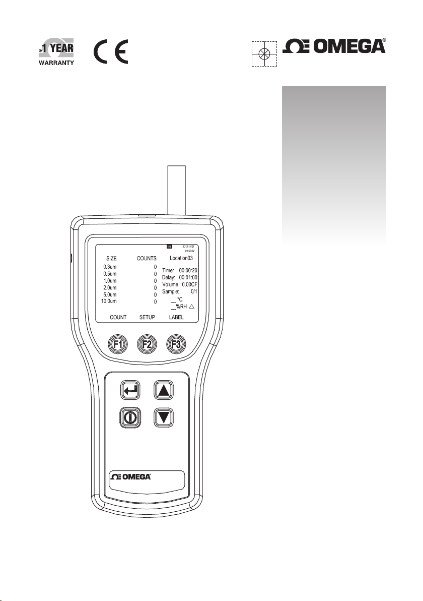
HHPT-51
Particle Counter
Page 2

omega.com [email protected]
Servicing North America:
U.S.A.:
Omega Engineering, Inc., One Omega Drive, P.O. Box 4047
Stamford, CT 06907-0047 USA
Toll-Free: 1-800-826-6342 (USA & Canada only)
Customer Service: 1-800-622-2378 (USA & Canada only)
Engineering Service: 1-800-872-9436 (USA & Canada only)
Tel: (203) 359-1660 Fax: (203) 359-7700
e-mail: [email protected]
For Other Locations Visit omega.com/worldwide
The information contained in this document is believed to be correct, but OMEGA accepts no liability for any errors it contains,
and reserves the right to alter specifications without notice.
WARNING: These products are not designed for use in, and should not be used for, human applications.
Page 3

CONTENTS
Title Page
1. SAFETY INFORMATION..........................................................1
2. GENERAL INFORMATION.......................................................2
3. SPECIFICATIONS ....................................................................3
4. QUICK START..........................................................................4
5. CONTROLS AND FUNCTIONS................................................5
6. DISPLAY...................................................................................6
6-1 Main screen............................................................................6
6-2 Setup Screen..........................................................................7
6-3 Label Menu Screen ................................................................8
7. USING THE METER...............................................................10
7-1 Setup....................................................................................10
7-2 Counter Operation................................................................15
8. MAINTENANCE......................................................................19
8-1 Cleaning the Case................................................................19
8-2 Charging the battery and using the AC adapter....................19
8-3 Purging the Meter Sensor.....................................................20
Page 4
SAFETY INFORMATION
1.
A Warning identifies a condition or action that pose hazard(s) to the
user; a Caution identifies a condition or action that may damage the
meter or the equipment under test.
Read this entire manual before using the meter.
Safety labels used in this manual and on the meter are as follows.
Precautionary labels
Label Meaning
Risk of Danger. Important information. Refer to manual.
Hazardous voltage. Risk of electrical shock.
Do not dispose of this product as unsorted municipal waste.
Conforms to relevant European Union directives.
To avoid electric shock, injury, or damage to the meter, follow
these safety guidelines:
Use the meter only as described in this Instruction Manual,
otherwise the protection provided by the meter may be
impaired.
Do not use the meter in explosive atmospheres.
The meter contains no user-serviceable parts. Do not open the
meter.
Have the meter serviced only by qualified service personnel.
Inspect the meter before use.
Do not use it if it appears damaged.
Always use the ac adapter/charger and connector appropriate
for the voltage and outlet of the country or location in which
you are working.
Warning
1
Page 5
Caution
To avoid possible damage to the meter:
Avoid using the meter in an excessively dirty or dusty
atmosphere.
Excessive particle intake can damage the meter.
Remove the isokinetic probe cap before the startup. Not doing
so can damage the meter.
Do not use a wrench to connect or disconnect the isokinetic
probe. Finger-Tighten the connection.
2. GENERAL INFORMATION
Warning
Read “Safety Information” before using the meter.
The meter is a portable instrument that measures and reports air
contamination. It holds 500 samples in memory and records the date,
time, counts, sample volume, temperature, and relative humidity of each
sample. The data can be easily downloaded to a personal computer
using the USB interface cable.
The meter is commonly used for the following:
Monitoring clean-rooms, manufacturing processes and pharmaceutical
production.
Indoor Air Quality (IAQ) monitoring.
Monitoring gowning rooms.
Testing filter seals.
Locating particle contamination sources.
Monitoring particle size distributions.
2
Page 6

3. SPECIFICATIONS
6 Particle size channels: 0.3, 0.5, 1.0, 2.0, 5.0, 10.0 µm
Flow rate: 0.1 cfm (2.83 L/min)
Light source: Laser diode
Calibration: PSL particles in air
Counting efficiency: 50 % at 0.3 µm; 100 % for particles > 0.45 µm
(per JIS B9921:1997)
Zero count: 1 count/5 minute (per JIS B9921:1997)
Coincidence loss: 5 % at 2,000,000 particles per cubic ft.
Relative humidity: ± 7 %, 20 % RH to 90 % RH, non-condensing
Temperature: ± 3 °C, 10 °C to 40 °C (50 °F to 104 °F)
Data storage: 500 sample records (rotating buffer)
D
ata recorded: Date, time, counts, relative humidity, temperature, sample
volumes, alarms, label
Display: TFT color display with backlight
Count modes: Concentration, totalize, audio
Delay time: 0 to 24 hours
Sample inlet: Isokinetic probe
Interface: USB
Vacuum source: Internal pump flow controlled
Dimensions: 11.0 x 21.8 x 6.7 cm (4.33 " x 8.58 " x 2.64 ")
Weight: 875 g
Environmental:
% RH, non-
Operating: 10 °C to 40 °C (50 °F to 104 °F), 20 % to
condensing
Storage: -10 °C to 50 °C (14 °F to 122 °F), Up to 90 % RH, non-
condensing
Power: AC Adapter, 12 VDC at 3 A, 100 to 240 VAC, 50 to 60 Hz
Rechargeable Battery: Lithium ion, 8.4 V at 2.5 Ah; replaceable
Charge time: 2 hours (Fast Charge mode), 27 hours (Trickle Charge
mode)
Continuous Operating Time: 4 hours
Standards: Complies with CE, JIS B9921: 1997, ISO 21501-4
Accessories: Instruction manual, AC adapter, Power cord, USB cable,
Zero count filter, Hardshell carrying case.
3
90
Page 7
QUICK START
4.
The meter may be used directly out of the box.
To immediately use the meter:
1. Read “Safety Information”
2. Remove the Isokinetic probe cap.
3. Press the (POWER) key.
4. Press
Be sure to read this entire manual for more detailed information.
F1
(COUNT) key to start sampling.
4
Page 8
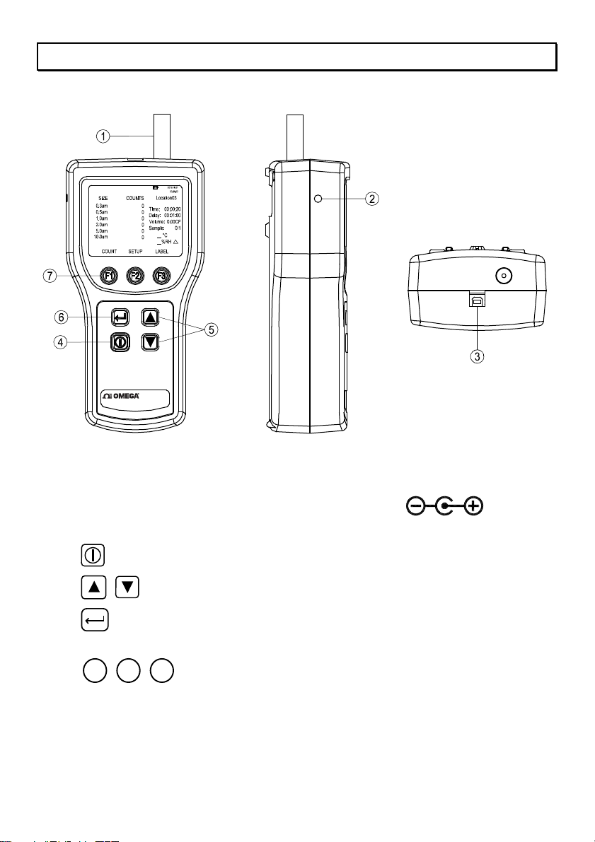
5. CONTROLS AND FUNCTIONS
Parts description:
HHPT-51
HHPT-51
PARTICLE COUNTER
1. Isokinetic probe and cap.
2. External power: 12 VDC, 3 A External power.
3. USB Port.
4. Power key: Press to turns the meter on and off.
5.
6.
Arrow keys: Press to scroll within the selected screen.
Return key: Press to store the setup changes and to return to
the main screen.
F2
7.
F1
F3
Function keys: Each function key corresponds to
a name above each function key.
Different menus have different
labels above the keys.
5
Page 9
6. DISPLAY
Press the corresponding button from the keypad at the bottom of the
LCD to invoke the following screens:
❏ Main screen
❏ Setup screen (pages 1 and 2)
❏ Label menu screen
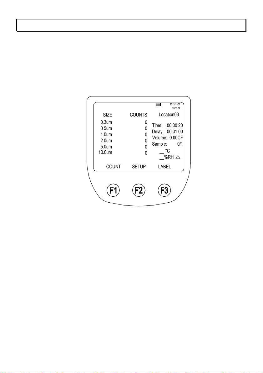
6-1 Main screen
HHPT-51
The Main screen appears after the meter is turned on and after the
opening screen appears.
The Main screen includes:
❏ Six channel sizes and corresponding counts.
❏ Battery-charge indicator (amount of charge remaining in the battery).
❏ Sample location name.
❏ Time indicator (represents time to complete).
❏ Delay time.
❏ Sampled volume indicator.
❏ Number of samples.
❏ Sample air temperature (°C or °F).
❏ Sample air relative humidity (%RH).
❏ Particle count mode.
The par
ameters on
the Main screen are selected by using the Setup
screens and the Label setup menu.
6
Page 10
Page 11
Page 12

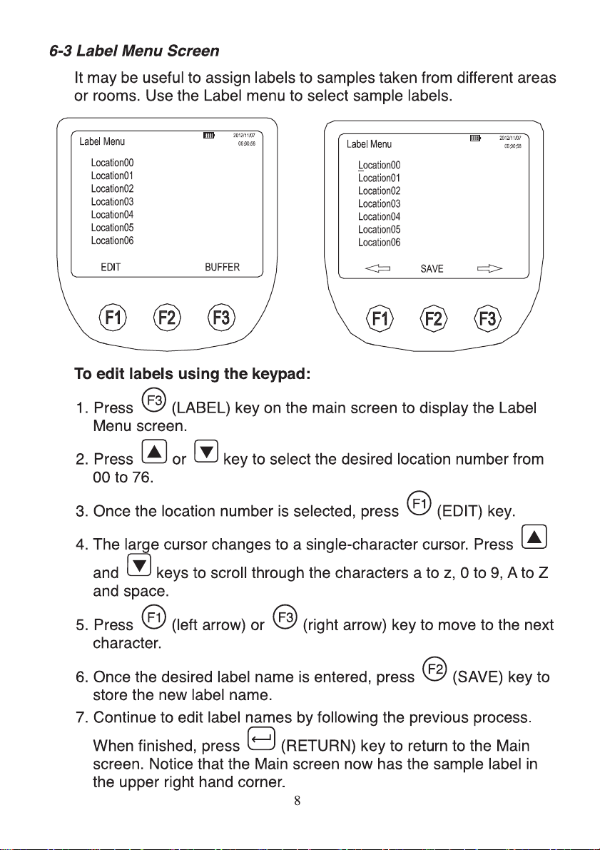
viewing the buffer:
Re
To review the buffer from the Label menu, press
to recall the buffer and press
or
key to scroll through the
different samples.
The Label menu screen includes:
List of location labels.
F3
(BUFFER) key
9
Page 13

USING THE METER
7.
The following sections give detailed information about using the meter.
7-1 Setup
To set up the meter:
Go through the different screens and set the desired parameters for
sampling. Refer to previous sections regarding the different screens
and menus.
7-1-1 Setting the Counting mode:
The counting mode choices are:
Concentration mode:
The Concentration mode is used to take a quick glimpse of
airborne particle contamination levels. For example, this mode
might be used in areas where particulate levels are unknown and
may exceed the operating levels of the meter. The meter
estimates the count per cubic foot or liter depending on the volume
selected. This mode should not be substituted for full sampling.
Totalize mode:
In Totalize mode, the particle counts are display and
accumulate as sampled. When the sample is complete, the
record is stored and the value is displayed on the screen until
the next sample is started.
Audio mode:
In Audio mode, the meter beeps once each time the alarm limit
is exceeded. For example, if the limit is set to 10, the meter
beeps when the count first reaches 10 and beeps again for
every multiple of 10. In Audio mode, the display shows counts
as in Totalize mode.
To set the counting mode:
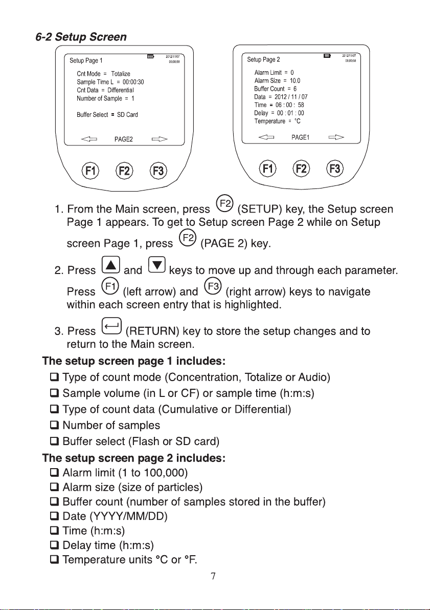
1. Press
screen is displayed with the current “Cnt Mode” field is selected.
2. Press
desired count mode.
F2
(SETUP) key on the Main screen. The Setup page 1
F1
(left arrow) or
F3
(right arrow) key to select the
3. When the desired mode shows on the screen, press
ETURN) key to select that mode and return to the Main
(R
screen.
10
Page 14
1-2 Setting the air sampling volume or sampling time:
7-
To set the sample volume or sample time:
F2
1. Press
(SETUP) key on the Main screen. The Setup page 1
screen is displayed with the current “Cnt Mode” field is
selected.
2. Press
key to move to the “Sample Volume” or “Sample
Time” field.
3. To select a sample volume, sample time, or to manually stop
the meter, press
F1
(left arrow) or
F3
(right arrow) key.
If Sample Time CF or Sample Time L is selected:
4. Press
5. Press
F2
(EDIT) key to edit the sampling time.
F1
(left arrow) or
F3
(right arrow) key to highlight the
desired hours, minutes, or seconds digit.
6. Once the hours, minutes or seconds digits are selected, press
7. Press
or
ey to change the values.
k
F2
(Save) to save the settings and return to the
previous screen.
8. Press (RETURN) key to select the desired volume or time
and return to the Main screen. The time selected appears on
the right of the Main screen.
In Sample volume mode the display shows the calculated time in
either liters or cubic feet, based on the volume selected.
The choices for the sample volume setting are:
1.0L (counts for 21 seconds)
2.83L (60 seconds)
10.0L (3.53 minutes)
28.3L (10 minutes)
0.01CF (6 seconds)
0.1CF (60 seconds)
1.0CF (10 minutes)
MANUAL - Select this option to continuously sample and
display the counts until the unit is stopped manually. The
display shows the total volume sampled in Liters.
11
Page 15
1-3 Setting the method of counting data:
7-
The choices for data counting are:
Cumulative – Includes all particles that are larger than or equal to
the particle size selected in the sample volume field.
Differential – Includes all particles that are larger than or equal to
the particle size selected in the sample volume field, but small
than the next largest particle size.
To set the method for counting data:
F2
1. Press
(SETUP) key on the Main screen. The Setup page 1
screen is displayed with the current “Cnt Mode” field is selected.
2. Press
3. Press
key to move to the “Cnt Data” field.
F1
(left arrow) or
F3
(right arrow) key to change the
method of counting data.
4. Press (RETURN) key to select the desired data counting
method and to return to the Main screen.
The method selected appears as a symbol on the display.
The SUM symbol ( Σ ) denotes the Cumulative method and the
DELTA symbol (
) denotes the Differential method.
7-1-4 Setting the number of samples:
To set the number of samples:
1. Press
F2
(SETUP) key on the Main screen. The Setup page 1
screen is displayed with the current “Cnt Mode” field is
selected.
2. Press key to move to the “Number of Samples” field.
3. Press
F1
(left arrow) or
F3
(right arrow) key to select the
desired number of samples.
4. When the desired number appears, press (RETURN) key
to return to the Main screen.
Note: When choosing the number of samples, “INF” denotes infinite and
the unit will continue to take samples until the stop key is pressed.
12
Page 16
1-5 Setting the memory buffer:
7-
The meter can store measurement data in the internal flash
memory or on micro SD card.
To set the memory buffer:
F2
1. Press
(SETUP) key on the Main screen. The Setup page 1
screen is displayed with the current “Cnt Mode” field is selected.
2. Press
ey to move to the “Buffer Select” field.
k
3. Use
F1
(left arrow) or
F3
(right arrow) to select “Flash” or
“SD Card”.
4. Press (RETURN) to save the choice and return to the
Main Screen.
7-1-6 Setting the alarm count and size:
When the alarm is set, an audible alarm is triggered when counts
reach the count limits on the selected particle size.
To set the alarm count and size:
1. Press
F2
(SETUP) key on the Main screen. The Setup Page 1
screen is displayed.
2. Press
F2
(PAGE 2) key on the Setup Page 1 screen. The
Setup Page 2 screen is displayed.
3. Alarm Limit is highlighted. Press
F1
(left arrow) or
arrow) key to move the alarm limits from zero (no alarm) to
100,000 in factors of 10.
4. When the required limit is selected, press k
ey to select the
“Alarm Size” field.
5. Press
F1
(left arrow) or
F3
(right arrow) key to display the
various particle sizes.
F3
(right
6. Select the desired particle size and press (RETURN) key
to return to the Main screen.
F1
Note: When the alarm sounds, pressing
the alarm. Pressing
F1
STOP) key again will stop the sample.
(
13
STOP) key once will mute
(
Page 17
1-7 Setting the date and time:
7-
To set the date and time:
F2
1. Press
(SETUP) key on the Main screen. The Setup Page 1
screen is displayed.
2. Press
F2
(PAGE 2) key on the Setup Page 1 screen. The
Setup Page 2 screen is displayed.
3. Press
or
key to move the cursor to “Date” or “Time”
field.
F1
4. Press
this mode, press
(PROGRAM) key to enter the edit mode. Once in
and
eys to increase or decrease
k
the selected entry.
5. Use
F1
(left arrow) and
F3
(right arrow) to change the entry
selected.
6. Once the correct data has been entered, press
to store the data.
7. Press (RETURN) key to return to the Main screen.
7-1-8 Setting a delay between samples:
If continuous sampling is not necessary, a delay can be set. The
delay timer allows a “time out” between automatic samplings.
To set a delay time:
1. Press
F2
(SETUP) key on the Main screen. The Setup Page 1
screen is displayed.
2. Press
F2
(PAGE 2) key on the setup Page 1 screen. The
Setup Page 2 screen is displayed.
F2
(SAVE) key
3. Press key to move the cursor to “Delay” field.
F1
4. Press
5. Use
PROGRAM) key to enter the edit mode.
(
F1
left arrow) and
(
F3
right arrow) key to move to the
(
desired unit of time (hours, minutes, or seconds).
14
Page 18
Press
6.
to increase the time; press
time.
7. Once the desired time has been selected, press
key.
8. Press (RETURN) key to return to the Main screen.
Note: The maximum delay time is 23:59:59.
7-1-9 Setting the temperature unit:
To set the Temperature unit to ° F or ° C:
o decrease the
t
F2
(SAVE)
1. Press
F2
(SETUP) key on the Main screen. The Setup Page 1
screen is displayed.
2. Press
F2
(PAGE 2) key on the setup Page 1 screen. The
Setup Page 2 screen is displayed.
3. Press
2. Use
F1
(left arrow) or
or
ey to move the cursor to “Temperature”.
k
F3
(right arrow) key to select “°F” or
“°C”.
3. Press (RETURN) key to save the choice and return to the
Main screen.
7-2 Counter Operation
Once the meter configuration is set:
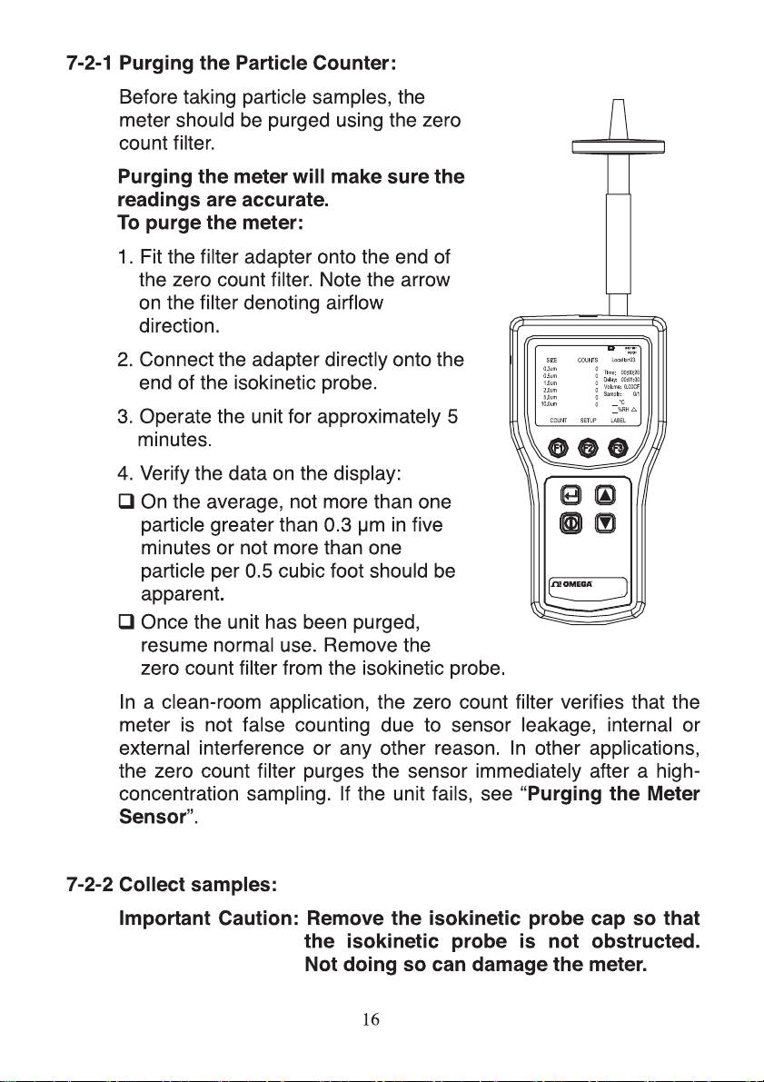
Use the zero count filter to purging the meter.
Collect the air samples.
Transfer the data from the air sample to PC for further analysis.
Review the number of samples in the buffer.
Clear the buffer if necessary.
15
Page 19
HHPT-51
PARTICLE COUNTER
HHPT-51
Page 20
collect samples:
To
1. Press the
(POWER) key to turn on the meter.
2. If needed, select the required setting on the setup screen.
Press
F2
(SETUP) key, than select the required settings on
the setup Page 1 screen.
3. Press
F2
(Page 2) key to select the required settings on the
setup Page 2 screen.
4. Press (RETURN) key to return to the Main screen.
5. Use
F1
(Count) on the Main screen to start sampling. The
cycle will automatically stop on completion of the sample. If the
Sample Volume is set to Manual, the meter will continuously
samples until the
F1
(Stop) key is pressed.
7-2-3 Transfer sample data to PC:
To transfer sample data from the meter to a PC:
1. Connect USB cable to PC and the meter.
2. Power on the PC, until the PC into the Window screen then
press the (POWER) key to turn on the meter.
7-2-4 Storing samples data:
The meter stores each sample data in a 500-record rotating buffer.
Data is stored in a “first in, first out” order. Thus, when the 501st
record is saved, the first record is automatically deleted, leaving a
total of 500 records.
7-2-5 Review the buffer:
To review the buffer:
1. Press
F3
(LABEL) key on the Main screen. The Label Menu
screen is displayed.
F3
2. Press
BUFFER) key, the Buffer Review screen and the
(
last record stored in the buffer is displayed.
17
Page 21
Press
3.
or
ey to select the record displayed. The user
k
can scroll from the newest to the oldest or the oldest to the
newest data record in the buffer.
4. Press
(RETURN) key to return to the Main screen.
7-2-6 Display the number of samples in the buffer:
To display the number of samples in the buffer:
1. Press
2. Press
F2
(SETUP) key on the Main screen.
F2
(PAGE 2) key on the Setup screen.
The number of samples in the buffer is displayed in the “Buffer
Count” field.
7-2-7 Clearing the buffer:
At some point, the user may wish to clear the meter buffer.
To clear the buffer:
1. Press
F2
(SETUP) key on the Main screen.
2. Press F2 (PAGE 2) key, the Setup Page 2 screen is displayed.
3. Press key to move the cursor to “Buffer Count”. Buffer
Count displays the number of samples stored in memory.
4. Use
F1
(left arrow) or
F3
(right arrow) key to select “Clear
Buffer”.
5. Press
F2
(CLEAR) key to clear the buffer.
6. Press (RETURN) key to return to the Main screen.
18
Page 22
MAINTENANCE
8.
The Meter contains no user-serviceable parts. To avoid electric shock,
injury, or damage to the meter, do not open the meter.
Use the zero count filter to ensure that the meter filter is free of contamination.
Refer to “Purging the Meter”.
8-1 Cleaning the Case
Periodically wipe the case with a damp cloth and mild detergent.
To avoid damaging the meter, do not use abrasives or solvents to
clean the meter case.
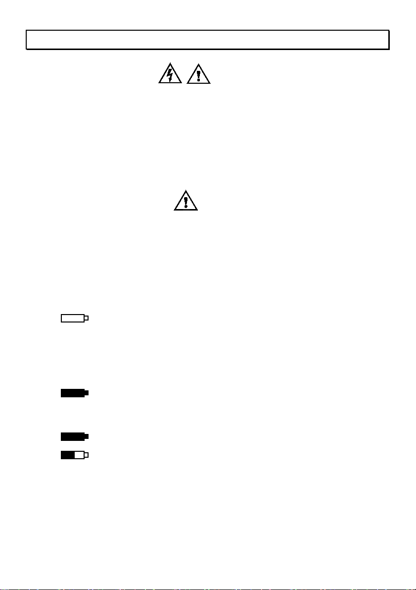
8-2 Charging the battery and using the AC adapter
Recharge the battery as soon as “LOW BATTERY” appears on the
display.
The battery symbols on the display show the status of the battery:
++ The battery is in “Fast Charge” mode.
The ac adapter is connected and the battery is charging.
When the battery is below 95 % of its charge, the meter
uses “Fast Charge” mode to bring the battery back up to
95 %.
Warning
Caution
+ The battery is in “Trickle Charge” mode. Once 95 % of the
charge is attained, the meter switches to “Trickle Charge”
mode to charge the remaining 5 % of the battery.
The battery is fully charged.
The battery is partially charged.
The ac adapter is used to recharge the battery as well as power the
meter. This feature allows the meter to be used while the battery is
charging.
19
Page 23

connect the ac adapter:
To
1. Attach the power cord to the end of the ac adapter.
2. Plug the ac adapter into the 12V jack on the meter.
3. Plug the power cord into an ac outlet. The meter will take two hours
to fully charge.
Note: If the Meter is powered off during charging (Trickle Charge mode),
the battery will require up to 27 hours for a full charge. To charge
the battery in 2 hours, the meter must be turned on while charging
(Fast Charge mode).
If the meter is charged while powered off (Trickle Charge mode)
the battery symbol in the display will not update to show the
actual charge status until the meter is turned on with the ac
adapter plugged in for approximately five minutes.
8-3 Purging the Meter Sensor
Caution
To avoid possible damage to the meter, avoid using the meter in an
excessively dirty or dusty atmosphere.
Excessive particle intake can damage the meter.
To purge the particle counter sensor:
1. Fit the adapter onto the end of the zero count filter.
Note the arrow on the filter denoting airflow direction.
2. Connect the adapter directly onto the end of the isokinetic probe.
3. Operate the unit for approximately 15 minutes.
4. On the average, not more than one particle greater than 0.3 µm in five
minutes or not more than one particle per 0.5 cubic foot should be
apparent.
Once the unit is purged, resume normal use. Remove the zero count filter
and adapter from the isokinetic probe.
20
Page 24

WARRANTY/DISCLAIMER
OMEGA ENGINEERING, INC. warrants this unit to be free of defects in materials and
workmanship for a period of 13 months from date of purchase. OMEGA’s WARRANTY adds
an additional one (1) month grace period to the normal one (1) year product warranty to
cover handling and shipping time. This ensures that OMEGA’s customers receive maximum
coverage on each product.
If the unit malfunctions, it must be returned to the factory for evaluation. OMEGA’s Customer
Service Department will issue an Authorized Return (AR) number immediately upon phone
or written request. Upon examination by OMEGA, if the unit is found to be defective, it
will be repaired or replaced at no charge. OMEGA’s WARRANTY does not apply to defects
resulting from any action of the purchaser, including but not limited to mishandling, improper
interfacing, operation outside of design limits, improper repair, or unauthorized modification.
This WARRANTY is VOID if the unit shows evidence of having been tampered with or shows
evidence of having been damaged as a result of excessive corrosion; or current, heat, moisture
or vibration; improper specification; misapplication; misuse or other operating conditions
outside of OMEGA’s control. Components in which wear is not warranted, include but are not
limited to contact points, fuses, and triacs.
OMEGA is pleased to offer suggestions on the use of its various products. However,
OMEGA neither assumes responsibility for any omissions or errors nor assumes
liability for any damages that result from the use of its products in accordance
with information provided by OMEGA, either verbal or written. OMEGA warrants
only that the parts manufactured by the company will be as specified and free of
defects. OMEGA MAKES NO OTHER WARRANTIES OR REPRESENTATIONS OF ANY
KIND WHATSOEVER, EXPRESSED OR IMPLIED, EXCEPT THAT OF TITLE, AND ALL
IMPLIED WARRANTIES INCLUDING ANY WARRANTY OF MERCHANTABILITY AND
FITNESS FOR A PARTICULAR PURPOSE ARE HEREBY DISCLAIMED. LIMITATION
OF LIABILITY: The remedies of purchaser set forth herein are exclusive, and the
total liability of OMEGA with respect to this order, whether based on contract,
warranty, negligence, indemnification, strict liability or otherwise, shall not exceed
the purchase price of the component upon which liability is based. In no event shall
OMEGA be liable for consequential, incidental or special damages.
CONDITIONS: Equipment sold by OMEGA is not intended to be used, nor shall it be used: (1)
as a “Basic Component” under 10 CFR 21 (NRC), used in or with any nuclear installation or
activity; or (2) in medical applications or used on humans. Should any Product(s) be used in or
with any nuclear installation or activity, medical application, used on humans, or misused in
any way, OMEGA assumes no responsibility as set forth in our basic WARRANTY / DISCLAIMER
language, and, additionally, purchaser will indemnify OMEGA and hold OMEGA harmless from
any liability or damage whatsoever arising out of the use of the Product(s) in such a manner.
Direct all warranty and repair requests/inquiries to the OMEGA Customer Service Department.
RETURN REQUESTS/INQUIRIES
BEFORE RETURNING ANY PRODUCT(S) TO OMEGA, PURCHASER MUST OBTAIN AN
AUTHORIZED RETURN (AR) NUMBER FROM OMEGA’S CUSTOMER SERVICE DEPARTMENT
(IN ORDER TO AVOID PROCESSING DELAYS). The assigned AR number should then be
marked on the outside of the return package and on any correspondence.
The purchaser is responsible for shipping charges, freight, insurance and proper packaging to
prevent breakage in transit.
FOR WARRANTY RETURNS, please have
the following information available BEFORE
contacting OMEGA:
1. Purchase Order number under which
the product was PURCHASED,
2. Model and serial number of the product
under warranty, and
3. Repair instructions and/or specific
problems relative to the product.
OMEGA’s policy is to make running changes, not model changes, whenever an improvement is possible.
This affords our customers the latest in technology and engineering.
OMEGA is a registered trademark of OMEGA ENGINEERING, INC.
© Copyright 2014 OMEGA ENGINEERING, INC. All rights reserved. This document may not be copied, photocopied,
reproduced, translated, or reduced to any electronic medium or machine-readable form, in whole or in part, without
the prior written consent of OMEGA ENGINEERING, INC.
FOR NON-WARRANTY REPAIRS,
consult
OMEGA for current repair charges. Have the
following information available BEFORE
contacting OMEGA:
1. Purchase Order number to cover the
COST of the repair,
2. Model and serial number of theproduct, and
3. Repair instructions and/or specific problems
relative to the product.
Page 25

Where Do I Find Everything I Need for
Process Measurement and Control?
OMEGA…Of Course!
Shop online at omega.com
TEMPERATURE
MU
Thermocouple, RTD & Thermistor Probes, Connectors, Panels & Assemblies
MU
Wire: Thermocouple, RTD & Thermistor
MU
Calibrators & Ice Point References
MU
Recorders, Controllers & Process Monitors
MU
Infrared Pyrometers
PRESSURE, STRAIN AND FORCE
MU
Transducers & Strain Gages
MU
Load Cells & Pressure Gages
MU
Displacement Transducers
MU
Instrumentation & Accessories
FLOW/LEVEL
MU
Rotameters, Gas Mass Flowmeters & Flow Computers
MU
Air Velocity Indicators
MU
Turbine/Paddlewheel Systems
MU
Totalizers & Batch Controllers
pH/CONDUCTIVITY
MU
pH Electrodes, Testers & Accessories
MU
Benchtop/Laboratory Meters
MU
Controllers, Calibrators, Simulators & Pumps
MU
Industrial pH & Conductivity Equipment
SM
DATA ACQUISITION
MU
Data Acquisition & Engineering Software
MU
Communications-Based Acquisition Systems
MU
Plug-in Cards for Apple, IBM & Compatibles
MU
Data Logging Systems
MU
Recorders, Printers & Plotters
HEATERS
MU
Heating Cable
MU
Cartridge & Strip Heaters
MU
Immersion & Band Heaters
MU
Flexible Heaters
MU
Laboratory Heaters
ENVIRONMENTAL
MONITORING AND CONTROL
MU
Metering & Control Instrumentation
MU
Refractometers
MU
Pumps & Tubing
MU
Air, Soil & Water Monitors
MU
Industrial Water & Wastewater Treatment
MU
pH, Conductivity & Dissolved Oxygen Instruments
M5414/0614
 Loading...