

Page 1
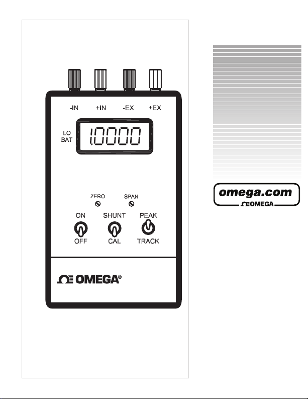
HHP-SG
User’s Guide
Shop on line at
®
®
www.omega.com
e-mail: [email protected]
For latest product manuals
www.omegamanual.info
HHP-SG
Handheld Strain Gage Indicator
Operator’s Manual
Page 2

omega.com [email protected]
Servicing North America:
U.S.A.: Omega Engineering, Inc., One Omega Drive, P.O. Box 4047
Stamford, CT 06907-0047 USA
Toll-Free: 1-800-826-6342 (USA & Canada only)
Customer Service: 1-800-622-2378 (USA & Canada only)
Engineering Service: 1-800-872-9436 (USA & Canada only)
Tel: (203) 359-1660 Fax: (203) 359-7700
e-mail: [email protected]
For Other Locations Visit omega.com/worldwide
The information contained in this document is believed to be correct, but OMEGA accepts no
liability for any errors it contains, and reserves the right to alter specifications without notice.
Page 3

1. Getting Started
1.1 Unpacking 1
1.2 General Description 1
1.3 Features 2
2. Safety Considerations 3
3. Installation and Operation
3.1 Front of the Meter 4
3.2 Rear of the Meter 6
3.3 Factory Settings 7
3.4 Battery Installation or Replacement 7
3.5 Transducer Hookup 8
4. Calibration, Gain Selection and Adjustments 9
4.1 Switches & Jumper Locations 9
5. Customized Scaling Procedure 15
6. Specifications 19
TABLE OF CONTENTS
i
Page 4

FIGURES
3.1 Front Panel 4
3.2 Rear View 6
4.1 Zero Calibration 9
TABLES
4.1
Gain Resistor Selection for 1.24 Volts Excitation Voltage
10
4.2
Gain Resistor Selection for 2.50 Volts Excitation Voltage
11
4.3
Zero Resistor Selection
12
4.4 S3 Jumper Switch Description 13
4.5 Solder Switch Description 13
5.1 Gain Switch Settings 18
FIGURES AND TABLES
ii
Page 5

SETUP
1
1
1.1 Unpacking
Remove the packing list and verify that you have received all
equipment. If you have any questions, contact the Customer
Service Department nearest you.
Upon receipt of shipment, inspect the container and equipment for
any signs of damage. Note any evidence of rough handling in
transit. Immediately report any damage to the shipping agent.
The carrier will not honor any claims unless all shipping
material is saved for their examination. After examining and
removing contents, save packing material and carton in the
event reshipment is necessary.
Please ensure that a 9 Volt battery is included.
1.2 General Description
The hand held calibrator is a digital indicator for strain gage type
transducers such as load cells, torque sensors, or millivolt pressure
sensors. It provides excitation voltage for the transducer and
displays the readings on a liquid crystal display (LCD). The LCD
has a 3 1/2 active digits (0-1999 counts) and an additional dummy
zero if needed. The calibrator can display either the actual value of
the signal (tracking mode) or the peak value (peak mode). It
operates on a standard 9 Volt battery and provides an indication of
low battery.
Page 6

SETUP
1
2
1.2 General Description (continued)
It has two internal reference voltages for powering the bridge. The
1.24 Volt reference is used with the 1K Ohm bridge and below
whereas the 2.5 Volt with the 2.5K/5K Ohm bridges and above.
Failure to properly select the excitation voltage can result in the
calibrator drawing excessive current.
(The calibrator provides amplification, common-mode rejection and
controls the LCD Display).
The calibrator is designed for 0.5 to 4.0 mV/V bridge sensitivity
range. A ZERO POT and SPAN POT is provided for calibration.
See Section 4 for more details.
1.3 Features
• Portable, hand held indicator for bridge type transducers
• 9 Volt battery powered
• Scalable display with dummy zero
• Built-in transducer excitation
• Track/peak modes available
• Selectable decimal point
• Low battery indication
• Blanking overrange
Page 7
SAFETY CONSIDERATIONS
2
3
This device is marked with the international Caution
symbol. It is important to read this manual before
installing or commissioning this device as it contains
important information relating to Safety and EMC
(Electromagnetic Compatibility).
Unpacking & Inspection
Unpack the instrument and inspect for obvious shipping
damage. Do not attempt to operate the unit if damage is found.
• Always disconnect power before changing signal and
power connections.
• Do not use this instrument on a work bench without its
case for safety reasons.
• Do not operate this instrument in flammable or
explosive atmospheres.
• Do not expose this instrument to rain or moisture.
• Allow for adequate ventilation to ensure instrument
does not exceed operating temperature rating.
• Use electrical wires with adequate size to handle
mechanical strain and power requirements. Install
without exposing bare wire outside the connector to
minimize electrical shock hazards.
EMC Considerations
• Whenever EMC is an issue, always use shielded
cables.
• Never run signal and power wires in the same conduit.
• Use signal wire connections with twisted-pair cables.
• Install Ferrite Bead(s) on signal wires close to the
instrument if EMC problems persist.
Page 8
INSTALLATION AND OPERATION
3
4
3.1 Front of the Meter
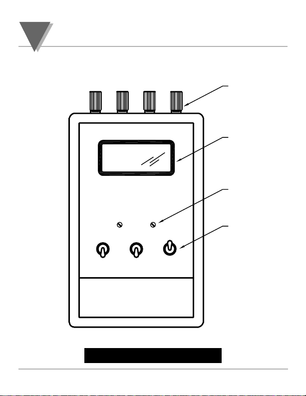
Figure 3.1 — Front Panel
BLACK REDBLACK RED
-IN +IN -EX
LO
BAT
ZERO SPAN
ON SHUNT PEAK
OFF CAL TRACK
+EX
TERMINALS
LCD DISPLAY
POTENTIOMETERS
SWITCHES
Page 9

INSTALLATION AND OPERATION
3
5
DESCRIPTION
ON/OFF Switch
—
controls power flow from the battery to all
circuits.
SHUNT CAL Switch
—
places a known resistor (59 K Ohm)
across the transducer, so that a known output (half scale, 1000
count approximately) is seen, and is used to self-calibrate the
instrument.
Note: a count of 1000 is applicable only to a 350 Ohm bridge.
PEAK/TRACK Switch
—
selects the mode of operation of the
instrument. In the PEAK mode, the instrument will retain the
reading of the most positive value detected during the operation. In
the TRACK mode, the instrument will continuously follow the
variations of the input signal. To reset the peak (when in peak
mode), merely switch the instrument to the track mode.
ZERO Potentiometer
—
is used to obtain a zero indication,
thus compensating for drifts and electrical offsets that may exist in
the transducer or the instrument.
SPAN Potentiometer - adjusts the fine gain of the amplifier. It
is used to assure proper gain-level setting per given transducer.
LCD Display
—
appears through a window on the front
panel. The LO-BATT indication appears at the upper left side of the
display and indicates when the 9 Volt battery has dropped below
5.2 Volts.
TERMINALS
—
Above the front panel are four connectors used
to power and read from the transducer. The front-panel label
describes the function of each terminal.
Page 10
INSTALLATION AND OPERATION
3
6
3.2 Back of the Meter
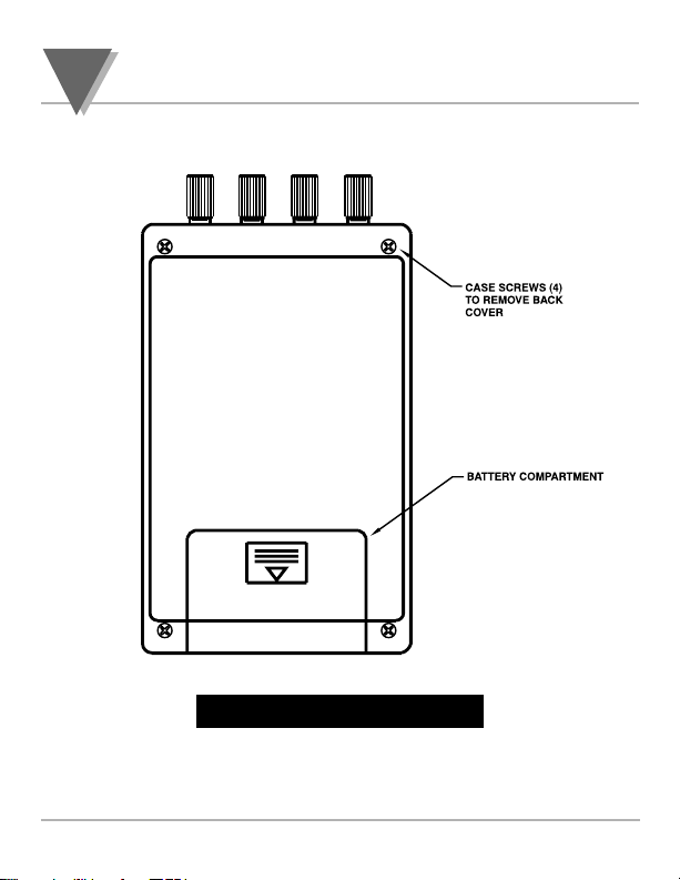
Figure 3.2 — Rear View
Page 11

INSTALLATION AND OPERATION
3
7
3.3 Factory Setting
The calibrator is factory configured to:
• 1XXX.0 decimal point location
• No dummy zero
• 2.5 Volt Transducer excitation
• 3 mV/V sensitivity
If any of the previous characteristics do not suit
your application, follow steps in Section 4 of this
manual to reconfigure to your needs.
3.4 Battery Installation or Replacement
3.4.1 Turn off the calibrator.
3.4.2 Remove the battery compartment door located on
the rear of the unit, sliding the door in the direction
of the arrow.
3.4.3 Remove the battery from the compartment and
carefully remove it from the battery clip. Do not pull
on the wires on either end.
3.4.4 Attach a new battery to the battery clip observing
polarity and place the battery back into its recess in
the case.
3.4.5 Replace the battery compartment door.
If you see (LO-BAT) in the upper left of the LCD,
the battery voltage is 5.2 Volts or less. It is time to
replace the battery.
Page 12

INSTALLATION AND OPERATION
3
8
3.5 Transducer Hookup
Connect the transducer to the calibrator using the binding
post connectors shown in Figure 3.1. Observe proper color
coding as shown on the Transducer Information Sheet
provided with your transducer. Allow the transducer to warm
up for a few minutes, to stabilize the drift.
Page 13
CALIBRATION & GAIN SELECTION
4
9
CALIBRATION, GAIN SELECTION AND ADJUSTMENTS
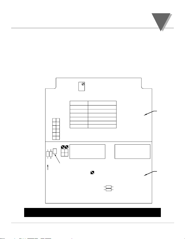
4.1 ZERO CALIBRATION
Close appropriate switches to obtain desired gain.
See Table 4.1 and 4.2 for proper selection. Gain
selection is the initial step for ZERO calibration. This
also provides course SPAN calibration as well.
Figure 4.1 — Switches & Jumper Locations
R4, R5 Not installed
R4
R5
V
U
T
S
R
Q
S3
1 2 3 4 5 6 7 8 9
GAIN
S1
C
B
R7
S8 S7
A
SOLDERSWITCH
R29
R28
1 2 3 4 5 6 7 8 9
OFFSET
S2
USED FOR
FACTORY
CALIBRATION
JUMPER
FUNCTION
Test Segment
DUMMY ZERO
1XXX.0
1XX.X0
1X.XX0
1.XXX0
V
U
T
S
R
Q
R7 SMT Not installed
Not installed
DISPLAY
BOARD
MAIN
BOARD
Page 14
CALIBRATION & GAIN SELECTION
4
10
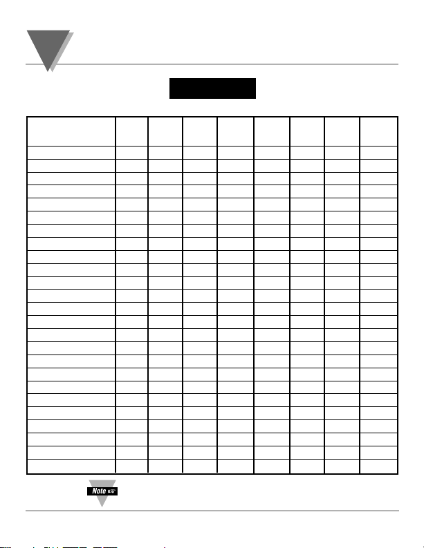
Table 4.1
GAIN RESISTOR SELECTION FOR 1.24 VOLTS EXCITATION VOLTAGE
(C=CLOSE / O=OPEN)
FOR 1.24V EXCITATION S1-8 CLOSED.
SENSITIVITY
S8 S1-7 S1-6 S1-5 S1-4 S1-3 S1-2 S1-1
(mV/V)
0.45 to 0.49 C C C C C C C C
0.50 to 0.54 C C C C O C C O
0.55 to 0.59 C C C O O O C O
0.60 to 0.65 C C O C O O O O
0.66 to 0.72 C O C C O C C O
0.73 to 0.79 C O O C O C C C
0.80 to 0.87 C O O C C O O O
0.88 to 0.96 C O O O C O O O
0.97 to 1.05 O C C C C O O C
1.06 to 1.16 O C C O C O C O
1.17 to 1.27 O C O C C O C O
1.28 to 1.40 O C O O O C C C
1.41 to 1.54 O C O O O O C C
1.55 to 1.70 O C O O O O C O
1.71 to 1.87 O O C C O C C C
1.88 to 2.06 O O C C C O O C
2.07 to 2.27 O O O C C C C C
2.28 to 2.49 O O C O C O C O
2.50 to 2.74 O O O C C C O C
2.75 to 3.02 O O C C O O O O
3.03 to 3.32 O O C O O C O O
3.33 to 3.65 O O O O C O C C
3.66 to 4.02 O O O O O C C C
4.03 to 4.42 O O O C O O C O
4.43 O O O O C C O O
Page 15
CALIBRATION & GAIN SELECTION
4
11
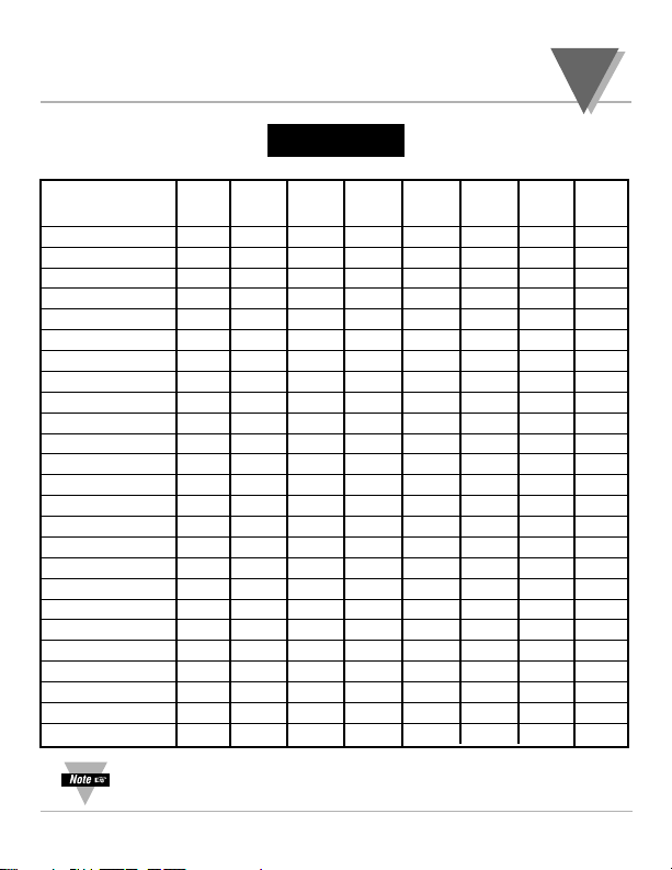
Table 4.2
GAIN RESISTOR SELECTION FOR 2.50 VOLTS EXCITATION VOLTAGE
(C=CLOSE / O=OPEN)
FOR 2.50V EXCITATION S1-9 IS CLOSED.
See NOTES 1, 2, and 3 at end of section.
SENSITIVITY
S8 S1-7 S1-6 S1-5 S1-4 S1-3 S1-2 S1-1
(mV/V)
0.45 to 0.49 O C C C C C O C
0.50 to 0.54 O C C O C O C C
0.55 to 0.59 O C C O O C C O
0.60 to 0.65 O C C O O C O O
0.66 to 0.72 O C C O O O O O
0.73 to 0.79 O C O O O C O C
0.80 to 0.87 O C O O O C O O
0.88 to 0.96 O O C O C C C C
0.97 to 1.05 O O C C O O C C
1.06 to 1.16 O O C C C O O O
1.17 to 1.27 O O C O C C O O
1.28 to 1.40 O O C O O C O C
1.41 to 1.54 O O C O C O O O
1.55 to 1.70 O O O C O C C O
1.71 to 1.87 O O O O C C O C
1.88 to 2.06 O O O C C O O O
2.07 to 2.27 O O O O C O C O
2.28 to 2.49 O O O O C C O O
2.50 to 2.74 O O O O O O C C
2.75 to 3.02 O O O O O C O C
3.03 to 3.32 O O O C O O O O
3.33 to 3.65 O O O O C O O O
3.66 to 4.02 O O O O O O C O
4.03 to 4.42 O O O O O C O O
4.43 O O O O O O O C
Page 16
CALIBRATION & GAIN SELECTION
4
12
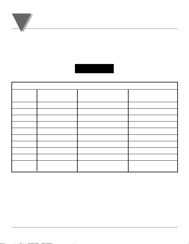
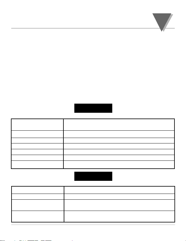
4.1.1 Apply zero signal.
4.1.2 Using Table 4.3, select and Close the appropriate
switches. (if any)
Table 4.3
ZERO RESISTOR SELECTION
4.1.3 This will provide coarse adjustment.
4.1.4 Use ZERO POT to fine tune to a display count of 000.
FUNCTION
SWITCH
ZERO OFFSET DISPLAY COUNT DISPLAY COUNT
VOLTAGE (1.24 VOLT EXC.) (2.50 VOLT EXC.)
S2-1 -40 mV -757 (±3) -729 (±3)
S2-2 -20 mV -373 (±3) -358 (±3)
S2-3 -10 mV -184 (±3) -177 (±3)
S2-4 -5 mV -90 (±3) -86 (±3)
S2-5 +5 mV +92 (±3) +87 (±3)
S2-6 +10 mV +186 (±3) +177 (±3)
S2-7 +20 mV +373 (±3) +357 (±3)
S2-8 +40 mV +756 (±3) +726 (±3)
S2-9 +80 mV +1543 (±3) +1478 (±3)
S2-None 0 mV 0 (±3) 0 (±3)
Page 17
CALIBRATION & GAIN SELECTION
4
13
4.2 SPAN CALIBRATION
4.2.1 Adjust ZERO POT to a 000 display count as
suggested in section 4.1.
4.2.2 Apply full scale signal per given strain gage. For
3mV/V and 1.24 V excitation, apply 3.720 mV at
± SIGNAL input.
4.2.3 Use SPAN POT to fine tune to a 1999 display count.
4.3 After proceeding through the steps above, apply a
ZERO signal again and check for a 000 display count.
If the ZERO has shifted, repeat the steps for ZERO
and SPAN calibration.
Table 4.4
S3 JUMPER SWITCH DESCRIPTION
Table 4.5
SOLDER SWITCH DESCRIPTION
JUMPER SWITCH
FUNCTION
SELECTED DECIMAL POINT POSITION
V TEST SEGMENT
U DUMMY ZERO
T 1XXX.0
S 1XX.X0
R 1X.XX0
Q 1.XXX0
SOLDER SWITCH FUNCTION
A Output is connected to SPAN POT. See NOTE 4.
B Gain Resistor R6 (750 Ohm) is selected.
See Table 4.1 and 4.2.
C Gain Resistor R7 (OPEN) is selected.
Default OPEN. See NOTE 5.
Page 18

CALIBRATION & GAIN SELECTION
4
14
1 The sensitivities increase in 10% increments. The SPAN
POT range is ±10% which should cover the entire sensitivity
range from 0.5 to 4.0 mV/V. Two extra through-hole resistor
locations R4, R5 and one surface mount resistor, R7 are
available for covering any sensitivity value not covered by
resistors in the tables above. (See Figure 4.1).
2 The required through hole resistor value can be
calculated by using the following formulas:
R-gain (Gain setting resistor) = 60,000/(Gain-4) where
Gain (Design gain) = V-out/(V-sensitivity x V-excitation)
Units are in Volts and Ohms.
3 The formulas above will give you the correct output when
the SPAN POT is connected to the circuit. With the SPAN
POT in the circuit, it will give you twice the desired output.
Therefore V-out equal to half the required output should
be used. Examples are shown below:
Example: V-out = 100 mV (a V-out of 100mV will give
you an actual output of 200mV) (1999
counts on the LCD Display)
V-sensitivity = 3 mV/V
V-excitation = 1.24 Volts
Gain = 100 mV/(3 mV/V x 1.24) = 26.9
R-gain = 60,000/(26.9-4) = 2.62 K Ohms
4 For SPAN POT to be connected and the output
adjustable, solder switch "A" needs to be Open.
5 R4, R5 can be any through-hole resistor value as
required.
R7 can be any surface mount resistor value as required.
Page 19

CUSTOMIZED SCALING PROCEDURE
5
15
5.1 CUSTOM SCALING PROCEDURE
Use this procedure if you desire to scale your Strain Guage
Indicator with other than the standard default scaling of 1999
counts equaling a full-scale reading.
1 Determine the full-scale reading you desire in terms of counts.
This must be between 0 and 1999 counts.
Example: You desire a full-scale reading of 500 counts to
correspond to an actual reading of 50.0 in/lbs.
2 Divide the number of counts determined in step 1 by 10 to
obtain the number of mV required to achieve the desired
counts.
Example:
500 counts
= 50 mV
10
3 Divide the number of mV obtained in step 2 by 2.
Example:
50 mV
= 25 mV
2
4 Determine the full-scale output of your device (load cell, strain
gage, etc.) in terms of mV.
Example: You have a torque cell with a full-scale output
sensitivity of 2.2249 mV/V. Multiply this value by the excitation
voltage you have selected. (e.g. 1.24V or 2.50V)
2.2249 mV/V x 1.24V = 2.7588 mV
5 Divide the result of step 3 by the result of step 4.
Example:
25 mV
= 9.06
2.7588
(This value is the amplifier gain that is necessary to give you
the full-scale reading you desire.)
Page 20
CUSTOMIZED SCALING PROCEDURE
5
16
6 Look up the gain value calculated in step 5 and find the
closest gain value in Table 5.1. (If the value of gain required is
not contained in Table 5.1, skip to step 14)
7 Read across the table to find the gain desired and the gain
switch settings necessary to give you that value.
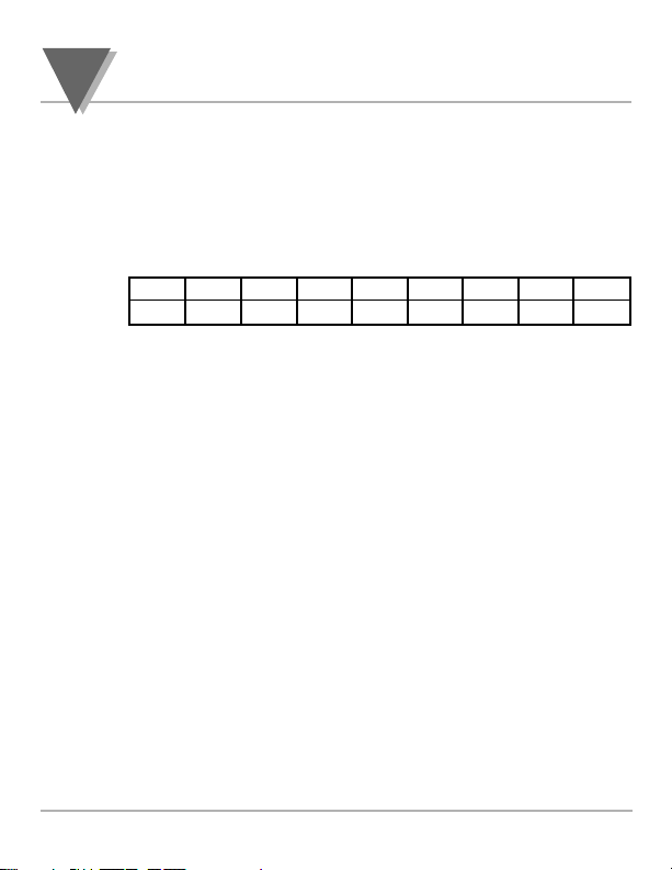
Table 5.1 (partial)
Example: S1-1 S1-2 S1-3 S1-4 S1-5 S1-6 S1-7 S8 GAIN
COOOOOOO9
8 Open up the Indicator case by removing the four screws which
hold the rear cover in place. (see Figure 3.2)
9 Set the gain resistor switches to the positions indicated in step 7.
(open is up, and closed is down)
10 Select the decimal point location (if desired) by using the
push-on jumpers “Q” through “T” on the display circuit board.
Also select the dummy zero (if desired) by installing the
push-on jumper “U” on the display circuit board.
11
Close the
Indicator
case by installing the four screws removed in
step 8.
12 Connect your device to the Indicator terminals.
13 Adjust the ZERO and SPAN pots on the Indicator as
necessary to obtain the exact reading you desire.
Page 21

CUSTOMIZED SCALING PROCEDURE
5
17
ALTERNATE PROCEDURE FOR GAINS OUTSIDE OF TABLE 5.1 RANGE
14 Use this procedure if the gain value calculated in step 5 is not
contained within Table 5.1.
15 Insert the result of step 5 into the following formula:
Rgain (ohms) =
60,000
(step 5 result - 4)
Example: Rgain (ohms) =
60,000
= 11,857 ohms
(9.06 - 4)
16 Obtain the nearest standard 1% resistor value that is closest
to the step 15 result.
Example: 11,857 ohms = 11,800 ohms
17 Open up the Indicator case by removing the four screws which
hold the rear cover in place. (see Figure 3.2)
18 Solder the resistor obtained in step 16 into the Indicator main
circuit board R4 or R5 location. (The main circuit board is the
one with the two 9-position DIP switches located on the board.)
19 Open up all other gain resistors by opening up S1-1 through
S1-7 switches (open is up, closed is down) and also open up
solder switches “B” and “C” and remove push-on jumpers S7
and S8 all on the main circuit board.
20 Select the decimal point location (if desired) by using the
push-on jumpers “Q” through “T” on the display circuit board.
Also select the dummy zero (if desired) by installing the pushon jumper “U” on the display circuit board.
21 Close the Indicator case by installing the four screws removed in
step 17.
22 Connect your device to the Indicator terminals.
23 Adjust the ZERO and SPAN pots on the Indicator as
necessary to obtain the exact reading you desire.
Page 22
CUSTOMIZED SCALING PROCEDURE
5
18
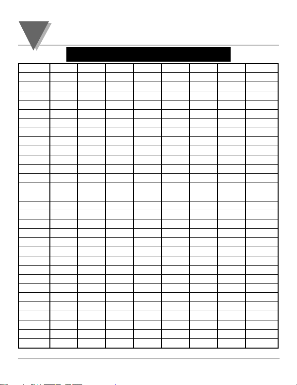
Table 5.1 Gain Switch Settings
S1-1 S1-2 S1-3 S1-4 S1-5 S1-6 S1-7 S8 GAIN
CCCCCCCC176
CCCOOCCC159
CCCOOOCC143
COCCCCOC129
OCOCOCOC116
CCOCOOOC104
OOOOCOOC93
OOOOOOOC84
OCOCOCCO76
OOCCCOCO68
OOOOOCCO61
OOOOCOCO54
COCCCCOO49
OOCCCCOO44
COCCOCOO40
OCOCOCOO36
CCOOOCOO32
OOOCOCOO29
COOOOCOO26
COCCOOOO23
OOOCCOOO21
OCOCOOOO19
OCCOOOOO17
COCOOOOO15
OOOOCOOO13
OOOCOOOO12
OCOOOOOO11
OOCOOOOO10
COOOOOOO 9
OOOOOOOO4
(C=CLOSE / O=OPEN)
Page 23

SPECIFICATIONS
6
19
Accuracy: ± 0.1 %
Supply Voltage: 9 Vdc Transistor Battery
Battery Life: 15 hours minimum with 350 ohm
bridge transducer
Supply Current: 20 mA Maximum (350 Ohm Bridge)
Display Output: 3 1/2 Digit LCD Display with Dummy
Zero, (1999 counts FS)
Digit Height: 0.4”
Bridge Resistance: 350 ohm to 5K ohm
MinimumTransducer
Resistance: 350 ohms
Transducer Excitation: 1.24 Vdc or 2.50 Vdc
Input Signal Sensitivity: 0.5 TO 4 mV/V for full-scale indication
of 1999 counts
Conversion Rate: 3 Readings per second
Rollover Error: ± 1 Count maximum
Linearity: ± 1 Count maximum
CMRR: 100 dB
Overvoltage Protection: 15 Vdc Maximum
Excitation Output: 5 mA Maximum (not short circuit
protected)
Operating Temp. Range: 0ºC to 70ºC (32ºF to 158ºF)
Storage Temp. Range: -15ºC to 85ºC (5ºF to 185ºF)
Humidity Level: 85% or less
Page 24

SPECIFICATIONS
6
20
Features: • Scalable display with dummy zero
• Selectable decimal point
• Low voltage indication @ 5.2 Volt
• Blanking overrange
• Peak Detector, < 0.03% per
minute bleed-off
Case: Molded ABS Plastic
Dimensions: 3.6" X 6.6" X 1.4"
(91.4 X 167.6 X 35.6mm)
Page 25

Where Do I Find Everything I Need for
Shop on line at www.omega.com
Process Measurement and Control?
OMEGA…Of Course!
TEMPERATURE
Thermocouple, RTD & Thermistor Probes, Connectors, Panels & Assemblies
Wire: Thermocouple, RTD & Thermistor
Calibrators & Ice Point References
Recorders, Controllers & Process Monitors
Infrared Pyrometers
PRESSURE, STRAIN AND FORCE
Transducers & Strain Gauges
Load Cells & Pressure Gauges
Displacement Transducers
Instrumentation & Accessories
FLOW/LEVEL
Rotameters, Gas Mass Flowmeters & Flow Computers
Air Velocity Indicators
Turbine/Paddlewheel Systems
Totalizers & Batch Controllers
pH/CONDUCTIVITY
pH Electrodes, Testers & Accessories
Benchtop/Laboratory Meters
Controllers, Calibrators, Simulators & Pumps
Industrial pH & Conductivity Equipment
DATA ACQUISITION
Data Acquisition & Engineering Software
Communications-Based Acquisition Systems
Plug-in Cards for Apple, IBM & Compatibles
Datalogging Systems
Recorders, Printers & Plotters
HEATERS
Heating Cable
Cartridge & Strip Heaters
Immersion & Band Heaters
Flexible Heaters
Laboratory Heaters
ENVIRONMENTAL
MONITORING AND CONTROL
Metering & Control Instrumentation
Refractometers
Pumps & Tubing
Air, Soil & Water Monitors
Industrial Water & Wastewater Treatment
M3369/0516
pH, Conductivity & Dissolved Oxygen Instruments
 Loading...