

Page 1
www.omega.com
[email protected]
1-800-826-6342
User Manual
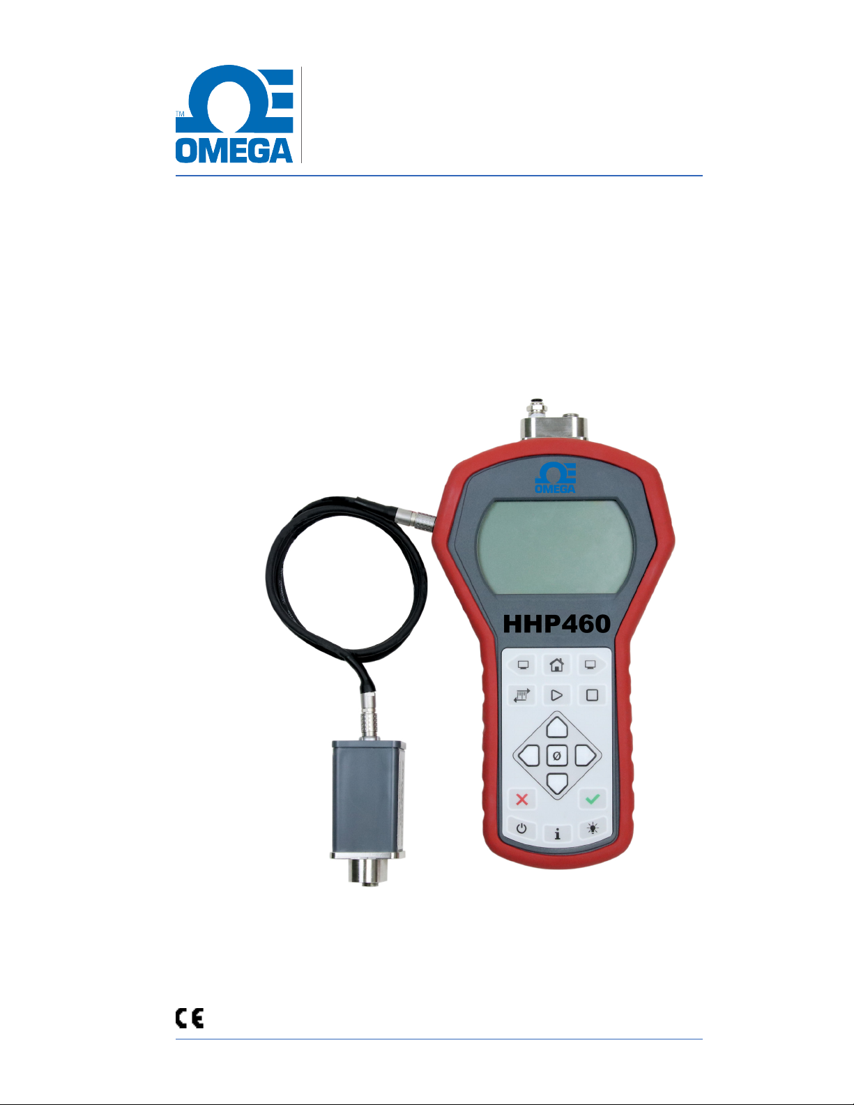
HHP
Smart Manometer
With Altimeter and Air Speed Tester
© Omega 2021
Page 2

M20013 REL-0000 (2103)
Contents
General Information ................................................................................................................................... 4
Notification Statements ...................................................................................................4
Glossary ...................................................................................................................................... 5
General warnings and cautions .......................................................................................................7
Preventing injury ..................................................................................................................7
Safety symbols .......................................................................................................................7
Sample label for General Purpose Smart Manometers ...........................8
Fire or explosion hazard ..................................................................................................8
For General Purpose Series .........................................................................................8
Do not exceed pressure limits .................................................................................... 9
Sensors .............................................................................................................................................................. 10
Omega Tethered Sensors .......................................................................................... 11
Overview of the temperature and pressure sensors ............................... 11
How to zero Absolute Sensors ................................................................................ 11
How to zero DN, DI, or CI sensors ........................................................................13
Altitude and Indicated Air Speed ................................................................................................ 14
ALT FEET or BEYOND MAX ...................................................................................... 14
IAS MPH .................................................................................................................................14
Altitude Correction in Feet (Meters) ................................................................... 15
Sea Level Correction in Meters .............................................................................. 16
Switch to Omega Tethered Sensor ............................................................................................ 18
Smart Manometer ..................................................................................................................................... 19
Battery and USB power ................................................................................................ 19
Batteries ................................................................................................................................... 19
The display ............................................................................................................................. 21
Keypad: Description of the keys ............................................................................ 23
The backlight ........................................................................................................................ 25
Measurement units .......................................................................................................... 27
Damping .................................................................................................................................. 28
Data Logging........................................................................................................................29
Leak Test .................................................................................................................................30
Relief Valve Test ................................................................................................................. 33
Display information from two sensors ...............................................................34
Auto O (Automatic shut o) ...................................................................................35
What does the Zero (ø) key do? ............................................................................. 36
HHP400 Suite application ................................................................................................................. 37
How does HHP400 Suite benefit you? .............................................................. 37
HHP400 Suite and USB Drivers required .......................................................37
Tips for using HHP400 Suite .................................................................................... 38
Connection status.............................................................................................................41
Configuration button ......................................................................................................43
User Calibration button ................................................................................................47
Data Log button ................................................................................................................. 49
User Manual HHP460 Smart Manometer with Altimeter & Air Speed Test
2 of 72
Page 3

M20013 REL-0000 (2103)
TSV file format ..................................................................................................................... 51
Application button ............................................................................................................ 61
Update button ...................................................................................................................... 62
Omega Tethered Sensors: type and range .................................................... 63
Overrange limit ................................................................................................................... 65
Temperature .......................................................................................................................... 65
Relative Humidity .............................................................................................................. 65
Vibration ..................................................................................................................................65
Ingress specifications .................................................................................................... 65
Altitude specifications ................................................................................................... 66
Indicated Air Speed specifications.......................................................................66
Keypad ...................................................................................................................................... 66
Media Compatibility ........................................................................................................ 67
Battery Type .......................................................................................................................... 67
EMC compliance ............................................................................................................... 68
Dimensional specifications ........................................................................................ 69
Weight .......................................................................................................................................69
Enclosure ................................................................................................................................69
Maintenance and cleaning ................................................................................................................70
Cleaning ................................................................................................................................... 70
Prepare the Smart Manometer for storage .................................................... 70
Register your product ........................................................................................................................... 71
Find downloads and documents ...........................................................................71
User Manual HHP460 Smart Manometer with Altimeter & Air Speed Test
3 of 72
Page 4

M20013 REL-0000 (2103)
General Information
Notification Statements
Disclaimer
Every precaution has been taken in the preparation of this
manual. Nevertheless, Omega assumes no responsibility for
errors or omissions or any damages resulting from the use of
the information contained in this publication, including, without
limitation, incidental, special, direct or consequential damages.
OMEGA MAKES NO REPRESENTATIONS OR WARRANTIES
WITH RESPECT TO THE ACCURACY OR COMPLETENESS OF
THE CONTENTS HEREOF AND SPECIFICALLY DISCLAIMS ANY
IMPLIED WARRANTIES OF MERCHANTABILITY OR FITNESS
FOR ANY PARTICULAR PURPOSE. Omega reserves the right to
revise this publication and to make changes from time to time in
the content hereof without obligation to notify any person of such
revision or changes.
In no event shall Omega be liable for any indirect, special,
incidental, consequential, or punitive damages or for any lost
profits arising out of or relating to any services provided by
Omega or its ailiates.
It is not possible for Omega to identify all foreseeable uses or
misuses, therefore all persons involved in commissioning, using,
or maintaining this product must satisfy their self that each
intended application is acceptable.
Copyright
This publication is proprietary to Omega and no ownership rights
are transferred. Neither this manual, nor any of the material
contained herein, may be reproduced without the prior written
consent of Omega.
Trademark information
Design Patent D769,141 for the Smart Manometer’s LCD display.
All other trademarks are the property of their respective owners.
User Manual HHP460 Smart Manometer with Altimeter & Air Speed Test
4 of 72
Page 5

M20013 REL-0000 (2103)
Glossary
Words and phrases with their definitions or explanations.
Words &
phrases
Blinking
FS
Home
Key and
button
Isolated
Customer
Calibration
Omega
Tethered
Sensor
Definitions or explanations
• It indicates the active edit field on an edit
screen.
• It indicates the displayed value is not actively
changing (like Hold or stopped Test).
• FS is the abbreviation of Full Scale.
• Home is the first screen that displays after
turning on the Smart Manometer. It’s the
screen with measurements and units on it.
• After you press the Home key in many other
screens, the Smart Manometer returns you to
Home.
• A key refers to hardware push-buttons on the
keypad that you can press.
• A button refers to an area in HHP400 Suite
that you can tap or click to select functions.
• The word isolated refers to the sensing
element being separated from the media. It
is commonly used in the phrases Absolute
Isolated (AI) pressure and Compound Isolated
(CI) pressure.
• Customer calibration refers to any calibration
done outside of Omega with non-Omega
traceability.
• Customer calibration includes: Multipoint
calibration or adjustment.
• An Omega Tethered Sensor always refers to
an external pressure sensor P2.
-- P1 --
• P1 on the display always refers to the internal
sensor.
-- P2 --
• P2 on the display always refers to the external
pressure sensor.
p1 .P2
• Data from the internal and external pressure
sensors display in two lines on the Smart
Manometer at the same time.
User Manual HHP460 Smart Manometer with Altimeter & Air Speed Test
5 of 72
Page 6

M20013 REL-0000 (2103)
Words &
phrases
P1.
DIFF P1-P2
Diff p2-p1
--out-
*P1
Definitions or explanations
• Data from the internal pressure sensor and
Omega Tethered Sensors temperature RTD
sensor display on the Smart Manometer at the
same time.
• The displayed result of the external pressure
measurement subtracted from the internal
pressure measurement.
• The displayed result of the internal pressure
measurement subtracted from the external
pressure measurement.
• --out- displays on the process readout
when the information readout is providing
information about exiting tests.
• The asterisk displays when you enable the
Sea Level Correction oset or enable the
Altitude Correction oset.
User Manual HHP460 Smart Manometer with Altimeter & Air Speed Test
6 of 72
Page 7
M20013 REL-0000 (2103)
General warnings and cautions
Preventing injury
Failure to follow all instructions could result in injury:
▪ Read the entire manual before using the Smart Manometer.
▪ Understand the contents before using the Smart Manometer.
▪ Follow all safety warnings and instructions provided with this
product.
Safety symbols
The following table defines the safety symbols, signal words,
and corresponding safety messages used in the manual. These
symbols:
▪ Identify potential hazards.
▪ Warn you about hazards that could result in personal injury or
equipment damage.
Safety symbols Explaining the symbols
Indicates a potentially hazardous situation
which, if not avoided, will result in death or
serious injury.
Indicates a potentially hazardous situation
which, if not avoided, could result in death
or serious injury.
Indicates a potentially hazardous situation
which, if not avoided, could result in minor
or moderate injury.
Indicates information essential for
proper product installation, operation or
maintenance.
User Manual HHP460 Smart Manometer with Altimeter & Air Speed Test
7 of 72
Page 8
M20013 REL-0000 (2103)
Sample label for General Purpose Smart
Manometers
All HHP400 Series models are available for general-purpose use.
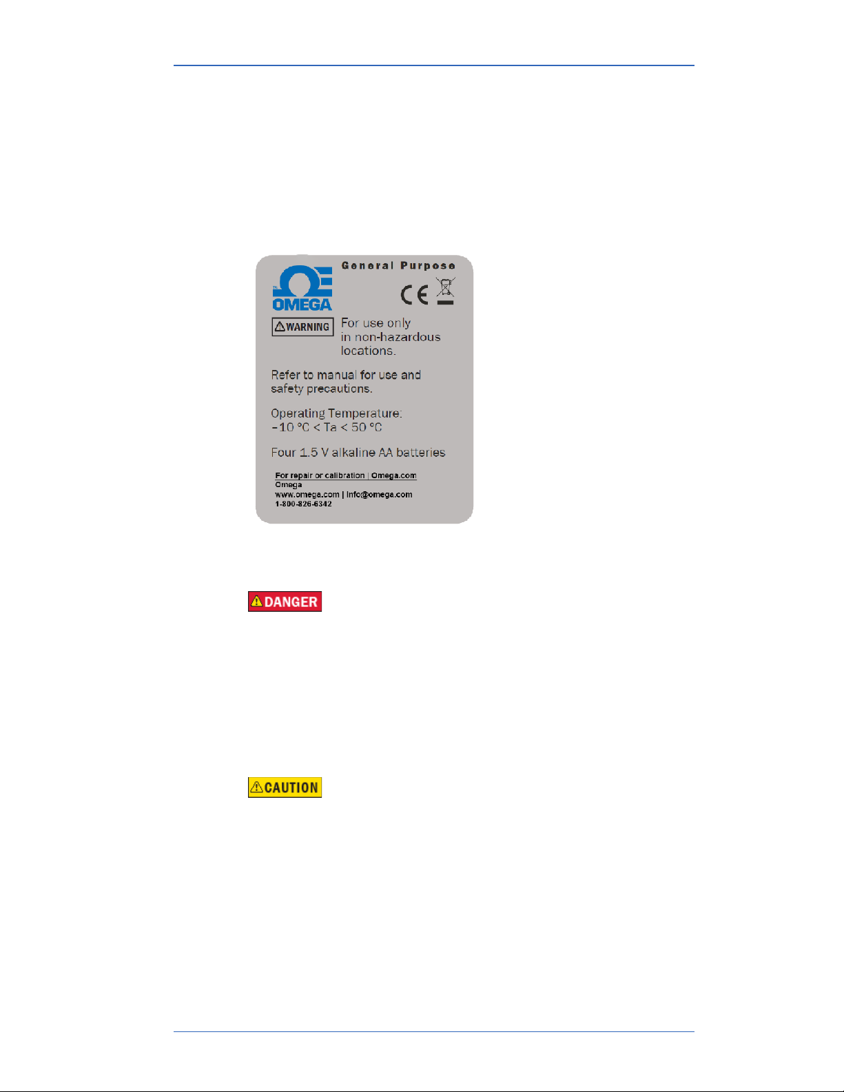
General Purpose (GP) versions are identified by the name plate
located on the rear of the unit under the protective rubber boot. A
sample of the General Purpose name plate is shown below:
Fire or explosion hazard
▪ Do not use General Purpose versions in hazardous areas.
▪ Do not use General Purpose versions in areas that may
contain flammable gas or vapors, combustible dusts or
ignitable fibers where an unintended spark can cause a fire or
explosion.
For General Purpose Series
Substitution of components may impair operation and safety.
▪ Disconnect power before servicing.
▪ Do not power the Smart Manometer with a combination of
new and old batteries.
▪ Do not power the Smart Manometer with a combination of
batteries from dierent manufacturers.
User Manual HHP460 Smart Manometer with Altimeter & Air Speed Test
8 of 72
Page 9

M20013 REL-0000 (2103)
Do not exceed pressure limits
▪ Do not exceed the Pressure Limits listed in the Specifications
section of this manual.
▪ Failure to operate within the specified pressure limit could
result in minor or moderate injury.
User Manual HHP460 Smart Manometer with Altimeter & Air Speed Test
9 of 72
Page 10

M20013 REL-0000 (2103)
Sensors
Overview of Sensors
This Smart Manometer can display two measurements: one from
the internal sensor and one from the optional tether sensor.
▪ P1 on this Smart Manometer always refers to the internal
sensor.
▪ P2 on this Smart Manometer always refers to the external
sensor.
Use two wrenches to install or remove pressure
connections
Connection: 1/8 in. female NPT, 316L SS.
▪ Always use a 3/4 in. wrench on the pressure manifold when
you install or remove the 1/8 in. NPT fitting.
▪ Applying torque to the manifold can damage the plastic
enclosure and voids the warranty.
▪ Do not over tighten.
Carefully equalize the pressure
Avoid these two issues with dierential sensors:
1. Connecting pressure to the incorrect pressure port on DN or
DI dierential pressure modules may cause damage to the
pressure sensor.
2. Applying pressure to either port before both connections are
made.
Apply pressure to both dierential ports at the same time.
Note: See Overrange limit in the section called Specifications
concerning overrange pressure limits. If over pressure damage
occurs, you must return the Smart Manometer to the factory for
sensor replacement.
User Manual HHP460 Smart Manometer with Altimeter & Air Speed Test
10 of 72
Page 11

M20013 REL-0000 (2103)
Omega Tethered Sensors
Overview of the temperature and pressure sensors
1. The P2 sensor sensor can be displayed with the P1 sensor.
2. When two sensors are displayed, no Units are displayed and
the Units key is disabled.
3. The Zero key is also disabled.
4. When a single sensor is selected it displays the measurement
units that were selected in HHP400 Suite.
Make an electrical connection
▪ Align the red dot on the Smart Manometer with the red dot on
the Tether cable and push in.
▪ Align the red dot on the Omega Tethered Sensors with the red
dot on the Tether cable and push in.
How to zero Absolute Sensors
Overview of the zeroing Absolute Sensors
The Smart Manometer is a stable and precise instrument.
However, on occasion the Smart Manometer should have a new
zero taken. The new zero removes a zero drift that can occur after
the Smart Manometer was last zeroed. The Smart Manometer can
be zeroed only if the new applied zero is within ± 1 % FS of the
original factory calibration zero. This prevents accidental zeroing
at atmospheric pressure or other relatively high pressures. If the
Smart Manometer is outside this limit, the Smart Manometer
cannot zero.
1. Referenced to Absolute Zero - This traditional and preferred
method takes a snapshot of the measured pressure when a
vacuum of less than 100 microns Absolute is applied to the
sensor.
2. Restore Factory Zero - This method restores the calibration
curve to the original zero taken at the factory.
Note: This feature is intended for comparison purposes, and
should not be used for real pressure measurement. This feature
does not compensate for any zero drift.
3. User Defined Oset (Zero) - With this method, you can
enter any pressure value when a known reference is applied
(for example: the local barometric pressure). The Smart
Manometer compares its actual measured value with the
User Manual HHP460 Smart Manometer with Altimeter & Air Speed Test
11 of 72
Page 12

M20013 REL-0000 (2103)
entered value and calculate a new zero reference based on the
oset.
Steps for zeroing Absolute Sensors
You can zero the Smart Manometer in one of three ways. The
following may appear in a dierent order depending on which
arrow key you press. When an absolute sensor displays on-screen
as P1 or P2, press the Zero key to see one of the three sets of
characters below and the following three messages
On-screen
message
TAP TO
CHOOSE REF
ARROWS TO
CHANGE REF
X Cancels
ab5 0
dflt
u5Er 0
Explanations
• Tapping the Accept key selects the displayed
reference.
• Tapping an Arrow key changes the displayed
reference.
• Tapping the Cancel key cancels the zero
request.
• This is the on-screen abbreviation for
Absolute Zero.
• This is the on-screen abbreviation for Default.
• If you want to restore the Factory Zero on a
sensor, press the Accept key when you see
these characters appear.
• This refers to User Defined Oset (Zero). You
can set an absolute reference point other than
zero.
User Manual HHP460 Smart Manometer with Altimeter & Air Speed Test
12 of 72
Page 13

M20013 REL-0000 (2103)
How to zero DN, DI, or CI sensors
1. Disconnect from a pressure source and vent the pressure port
to atmosphere.
1. Do not remove the factory installed P2 plug if it is present.
2. The display should read close to zero.
2. Press the Zero key.
The top line displays dashes ------.
3. The process is complete when the Smart Manometer returns
to the Home (Measurement Units) screen.
4. If someone has turned on the Password Required For Future
Access feature in HHP400Suite, the password feature does
not prevent you from zeroing the Smart Manometer.
Note: You can only zero the Smart Manometer if the new zero
value is within ± 5 % (of FS) of the original factory calibrated
zero. If the zero procedure generates a new zero reference
outside this limit, the procedure fails. Factory service may be
required.
5. You can turn o the Zero function in HHP400 Suite by
deselecting Allow zero adjust (Ø) in the Display Functions list.
User Manual HHP460 Smart Manometer with Altimeter & Air Speed Test
13 of 72
Page 14

M20013 REL-0000 (2103)
Altitude and Indicated Air Speed
ALT FEET or BEYOND MAX
When BEYOND MAX appears on screen
When BEYOND MAX appears on-screen instead of ALT FEET, the
calculated altitude exceeds 36,000 feet.
Note: Don’t confuse BEYOND MAX with an overrange condition.
If the sensor is outside the calibrated range, the HHP400
displays MEAS ERROR and the sensor may be damaged.
Display altitude in feet or meters
1. Press the Backward key to display ALT FEET (Altitude in Feet).
2. Press the Units key when ALT FEET is on-screen to switch
between FEET and METER and back to FEET.
IAS MPH
When you display IAS MPH (KNOTS or KM/H) on-screen, the
current, ambient pressure—the uncorrected barometric pressure—
is measured and is the reference pressure used for calculating air
speed.
When you switch from the IAS MPH screen to one of the other
display functions, the HHP400 does not hold that measurement
in memory. When you switch back to the IAS MPH screen, a new
pressure measurement is recorded and used as the reference
barometric pressure in the IAS MPH calculated air speed.
Switching from the IAS MPH screen to another display function,
and then switching back to the IAS MPH screen again while in
motion (IAS > 0), displays the wrong speed since IAS is reset
to zero (current measured pressure to reference barometric
pressure).
1. Press Backward two times from the home screen to display
IAS MPH (mi/h).
2. Press Units key when IAS MPH is on-screen to switch from
MPH to KNOTS to KM/H and back to MPH.
User Manual HHP460 Smart Manometer with Altimeter & Air Speed Test
14 of 72
Page 15

M20013 REL-0000 (2103)
Altitude Correction in Feet (Meters)
This User Defined Altitude function is useful in determining an
elevation change from a map elevation reference or from a survey
trig marker elevation. Follow the on-screen instructions to set up
the HHP400 to display altitude based on data you enter.
1. Press the Backward key three times from the home screen to
display ALTITUDE CORRECTION IN FEET TAP √ TO CHANGE.
2. Press the Accept (√ ) key to enter the change screen.
3. The HHP400 displays the following message:
ENABLE ALTITUDE OFFSET? √-YES X-NO
1. Pressing the Cancel (X) key returns you to the ALTITUDE
CORRECTION IN FEET TAP √ TO CHANGE screen.
2. Pressing the Accept (√) key displays Altitude Oset
options:
Note: When you Enable the Altitude Oset, an asterisk (*)
appears on the Home, the ALT FEET, and IAS MPH screens
to indicate that either an Altitude Oset or Sea Level Oset
has been set or both of Osets have been set. Pressing the
Information key displays ON or OFF for each active oset so
you can easily determine which osets are active.
4. The HHP400 displays the following message:
ALT OFFSET IN FEET √ SAVES X CANCELS 0 CLEARS
1. Pressing the Up or Down arrows on the keypad changes
the first digit and pressing the Right or Left arrows moves
the blinking cursor right or left. Enter your Defined Altitude
data by using the arrow keys.
2. Information: 0 Clears refers to the Zero key. Pressing it
clears any numbers you entered after pressing the Up or
Down arrow keys.
User Manual HHP460 Smart Manometer with Altimeter & Air Speed Test
15 of 72
Page 16

M20013 REL-0000 (2103)
3. Information: Pressing the Cancel (X) key returns you to
the ALTITUDE CORRECTION IN FEET TAP √ TO CHANGE
screen.
4. Information: The Accept key saves your ALT OFFSET IN
FEET data.
Sea Level Correction in Meters
Important: You can’t change from meters to feet; Sea Level
Correction is always in meters.
1. Press the Backward key four times from the home screen to
display the following message:
SEA LEVEL CORRECTION IN METERS TAP TO CHANGE.
1. ENABLE SEA LEVEL OFFSET? √-YES X-NO
2. NO returns you to the SEA LEVEL CORRECTION IN
METERS TAP TO CHANGE screen.
3. YES takes you to the edit screen. Pressing the Up or Down
arrows on the keypad changes the first digit and pressing
the Right or Left arrows moves the blinking cursor right
or left. Enter your Sea Level Correction data by using the
arrow keys.
4. While in the edit screen, the HHP400 displays the
following message: SEA LEVEL CORRECTION √ SAVES
XCANCELS 0CLEARS
User Manual HHP460 Smart Manometer with Altimeter & Air Speed Test
16 of 72
Page 17

M20013 REL-0000 (2103)
5. Information: 0 Clears refers to the Zero key. Pressing it
clears any numbers you entered after pressing the Up or
Down arrow keys.
6. Information: Pressing the Cancel (X) key returns you to
the ALTITUDE CORRECTION IN FEET TAP √ TO CHANGE
screen.
7. Information: The Accept key saves your ALT OFFSET IN
FEET data.
Note: Barometric pressures provided by the National Weather
Service and used at airports are always corrected to sea level.
Note: When you Enable the SEAL LEVEL CORRECTION Oset,
an asterisk (*) appears on the Home, the ALT FEET, and IAS
MPH screens to indicate that either an Altitude Oset or Sea
Level Oset has been set or both of Osets have been set.
User Manual HHP460 Smart Manometer with Altimeter & Air Speed Test
17 of 72
Page 18

M20013 REL-0000 (2103)
Switch to Omega Tethered Sensor
1. Attach an Omega Tethered Sensor to the HHP460.
2. From the Home screen, press the Up arrow to view all the
available information and options for the Omega Tethered
Sensor.
3. Use the optional HHP400 Suite application to configure,
calibrate, and update the Smart Manometer and use Data Log
for the Omega Tethered Sensors.
The following display functions are not available for the Omega
Tethered Sensor:
1. SEA LEVEL CORRECTION IN METERS TAP TO CHANGE
2. ALTITUDE CORRECTION IN FEET TAP TO CHANGE
3. IAS MPH
4. ALT FEET (Altitude Display) or BEYOND MAX.
User Manual HHP460 Smart Manometer with Altimeter & Air Speed Test
18 of 72
Page 19

M20013 REL-0000 (2103)
Smart Manometer
Battery and USB power
When you turn on the Smart Manometer, it draws power from the
batteries and the battery icon displays in the bottom row. When
you press the information button, it displays Batt %.
When you turn on the Smart Manometer and plug in the USB
cable to the computer, the Smart Manometer switches to the
power supplied by the USB cable. The battery icon disappears
from the bottom row. When you press the information button, it
displays USB POWER.
Do not use the USB in hazardous locations.
Batteries
Remove and replace batteries in non-hazardous (safe) areas only.
Turn o the backlight
▪ Turn o the backlight when you need to conserve battery
power.
▪ The backlight is dimmed when the Smart Manometer is in low
battery mode.
Suggested brands of batteries
The following is a suggested list of batteries.
▪ Duracell MN1500
▪ Duracell PC1500
▪ Energizer EN91
▪ Panasonic LR6XWA
▪ Rayovac 815
▪ Varta 4906
Note: The Smart Manometer is powered by four 1.5 volt AA size
batteries.
User Manual HHP460 Smart Manometer with Altimeter & Air Speed Test
19 of 72
Page 20

M20013 REL-0000 (2103)
Know your batteries
▪ Never mix batteries—not by manufacturer or by size, by
capacity, or by chemistry.
▪ Never mix old and new batteries.
▪ Remove all four batteries in the Smart Manometer at the same
time.
▪ Replace all four batteries with batteries from the same
package or with the same expiration date.
Install the batteries
1. Turn over the Smart Manometer so the display faces down.
2. Remove the two screws on the battery cover with the Phillipshead screwdriver by turning them counterclockwise.
3. Insert the four AA batteries.
Note: Pay attention to the positive (+) and negative (−) battery
polarity markings at the bottom of the compartment.
4. Replace the battery cover.
5. To secure the cover, torque the screws clockwise 2 in. lb.
maximum.
6. Do not over tighten.
To prevent internal damage to circuitry, do not substitute screws
with lengths that are dierent from the screws Omega provided to
you.
Watch for the low battery indicator
The battery indicator on the display shows the current charge.
Note: Be prepared to change batteries when you see the outline
of the battery icon and the outline of the battery icon flashes.
You have approximately 2 hours of run time following a low
battery warning.
Refer to battery manufacturers’ instructions
Visit the website of the battery manufacturer to learn more about
the care, storage, shipping, use, disposal, and recycling of your
batteries.
User Manual HHP460 Smart Manometer with Altimeter & Air Speed Test
20 of 72
Page 21
M20013 REL-0000 (2103)
The display
The bar graph
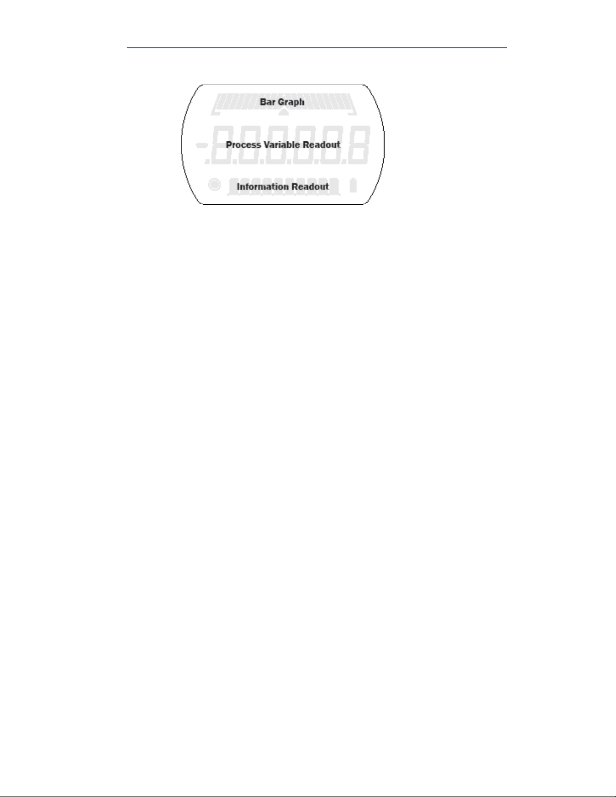
The bar graph displays a live indication of the current pressure or
temperature applied to a sensor as a percent of FS.
Note: When you press the Information key, the bar graph
displays the remaining state of the charge for the batteries.
User Manual HHP460 Smart Manometer with Altimeter & Air Speed Test
21 of 72
Page 22

M20013 REL-0000 (2103)
Display functions for the internal sensor
The Smart Manometer has sixteen display functions. It ships with
nine display functions active (they appear in bold below). You can
change which displays are active with HHP400 Suite.
Press the Forward (or Backward in reverse order) key to view
these modes.
1. Home is the default view with measurement units.
2. MIN (Minimum).
3. MAX (Maximum).
4. RELIEF VALVE TEST TAP START TO BEGIN.
5. + / - (Accuracy).
6. T.OFF, T.ON (Tare).
7. AVG (Average).
8. RATE.
9. DATA LOG.
10. Temperature & Time (internal sensors only).
11. LEAK TEST TAP START TO BEGIN.
12. LEAK TEST DURATION TAP TO CHANGE.
13. SEA LEVEL CORRECTION IN METERS TAP ✓ TO CHANGE.
14. ALTITUDE CORRECTION IN FEET TAP ✓ TO CHANGE.
15. IAS MPH.
16. ALT FEET (Altitude Display) or BEYOND MAX.
Display functions NOT appearing on the Omega Tethered
Sensor
The following display functions do not appear on an Omega
Tethered Sensor.
1. Temperature & Time (not on external sensor)
2. SEA LEVEL CORRECTION IN METERS TAP TO CHANGE
3. ALTITUDE CORRECTION IN FEET TAP TO CHANGE
4. IAS MPH
5. ALT FEET (Altitude Display) or BEYOND MAX.
User Manual HHP460 Smart Manometer with Altimeter & Air Speed Test
22 of 72
Page 23
M20013 REL-0000 (2103)
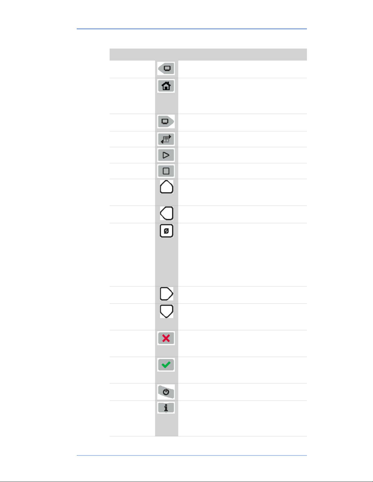
Keypad: Description of the keys
Name Key Description
Backward • It cycles backward through menu
options.
Home • Home key returns you to the
Measurement and Units screen.
• Home key is disabled during tests
and edits
Forward • It cycles forward through menu
options.
Units • Select a measurement unit.
Start • Start key begins a test or data log.
Stop • Stop or Hold (Freeze) key.
Up arrow • It increases digits by one.
• It switches between the P1 and P2
sensors displays.
Left arrow • It moves the blinking cursor one
space at a time to the left.
Zero & Tare • Zero key resets pressure values to
zero.
• It resets min max values.
• It sets edit values to zero.
• It resets relief valve test.
• As a Tare key, it turns o or turns on
the Tare function.
Right arrow • It moves the blinking cursor one
space at a time to the right.
Down Arrow • It decreases digits by one.
• It switches between the P1 and P2
sensors displays.
Cancel or Esc • Cancel any editing or changes
without saving.
• It also stops tests.
Accept • Accept applies all editing and
changes, and then saves them.
• It also stops tests.
Power • Turns the Smart Manometer on or o.
Information • Displays information about the Smart
Manometer, internal sensor, attached
Omega Tethered Sensors and the
firmware.
User Manual HHP460 Smart Manometer with Altimeter & Air Speed Test
23 of 72
Page 24

M20013 REL-0000 (2103)
Name Key Description
Backlight • It provides three levels of brightness
and o.
The Information key and the Home screen
The Information menu provides you with details about the Smart
Manometer and sensors.
Depending on what is attached to the Smart Manometer and
depending on what is selected in the bottom row in the LCD
display, determines what data appears.
1. Batt % displays the percentage on the bar graph and in digits
or it displays the words USB POWER.
2. SEA LEVEL CORRECTION: On or O
3. ALTITUDE CORRECTION: On or O
4. If you have an Omega Tethered Sensors attached to the Smart
Manometer.
-- P1 -- or -- P2 --
Note: the bottom row indicates sensor (or measurement type):
compound, absolute, or dierential. All the following sensor
information describes the sensor indicated by P1 or P2.
5. CAL DATE
6. USL is an abbreviation for upper sensor limit.
7. LSL is an abbreviation for lower sensor limit.
8. LT MAX % displays the Life-Time Maximum that has been
reached on the sensor.
9. SENSOR F/W VERS F/W is an abbreviation for firmware (this
message scrolls to display the information).
10. SENSOR S/N S/N is an abbreviation for serial number
(this message scrolls to display the information).
Note: SNSR NAME appears only with an Omega Tethered
Sensors (this message scrolls to display the information).
11. DEV F/W VER DEV is an abbreviation for device; it refers
to the Smart Manometer (this message scrolls to display the
information).
12. DEV S/N (this message scrolls to display the information).
13. DEV NAME (this message scrolls to display the information).
User Manual HHP460 Smart Manometer with Altimeter & Air Speed Test
24 of 72
Page 25

M20013 REL-0000 (2103)
Up and Down Arrows
In the edit mode, the Up Arrow increases the digit each time you
press it. The Down Arrow decreases the digit
and
1. Up Arrow: 0 to 1 to 2 to 3 to 4 to 5 to 6 to 7 to 8 to 9.
2. Down Arrow: –0 to –1 to –2 to –3 to –4 to –5 to –6 to –7 to –8
to –9.
3. The negative symbol in the display appears in front of the first
digit when it is required.
The backlight
White backlight
The white backlight has an automatic time out. If you do not press
any keys while the backlight is on, it automatically turns o after 1
minute.
Note: You can configure the backlight timeout using HHP400
Suite.
Levels of backlight intensity
Press the Backlight key to cycle through these choices:
▪ Low.
▪ Medium.
▪ High.
▪ O.
Flashing red backlight
The flashing red backlight indicates an error condition. Possible
error conditions are:
▪ Pressure has exceeded the calibrated accuracy of the Smart
Manometer.
▪ Pressure has fallen below the stated accuracy of the Smart
Manometer.
Note: The red backlight overrides the white backlight.
Overrange condition
During an error or overrange condition, the red backlight
overrides the white backlight.
User Manual HHP460 Smart Manometer with Altimeter & Air Speed Test
25 of 72
Page 26

M20013 REL-0000 (2103)
However, once the error or overrange condition is corrected, the
white backlight is restored to its previous state (if the backlight
Auto O timeout did not expire).
User Manual HHP460 Smart Manometer with Altimeter & Air Speed Test
26 of 72
Page 27

M20013 REL-0000 (2103)
Measurement units
A measurement unit doesn’t display
If a given measurement unit cannot display the correct number of
digits, the Smart Manometer automatically advances to the next
displayable unit.
Note: When you turn on the Smart Manometer, it defaults to the
last selected measurement unit.
Measurement units are stored on a sensor
The HHP400 Suite application gives you the ability to configure
specific measurement units on specific sensors.
A total of 32 measurement units are available in HHP400 Suite.
When the Smart Manometer is shipped, 12 measurement units are
active. The 12 units appear in bold type in the following list.
Standard Measurement Units (non-custom)
1. PSI 12. CMW4C 23. KG/M2
2. INW20C 13. CMW60F 24. PA
3. INW4C 14. MW2OC 25. HPA
4. INW60F 15. MW4C 26. KPA
5. FTW2OC 16. MW60F 27. MPA
6. FTW4C 17. INHG0C 28. BAR
7. FTW60F 18. MGH0C 29. MBAR
8. MMW20C 19. CMGH0C 30. ATM
9. MMW4C 20. MMHG0C 31. OZ/IN2
10. MMW60F 21. TORR 32. LB/FT2
11. CMW2OC 22. KG/CM2
User Manual HHP460 Smart Manometer with Altimeter & Air Speed Test
27 of 72
Page 28

M20013 REL-0000 (2103)
Damping
Damping rate
Select a Time Constant: 1 second, 2 seconds, 4 seconds,
8seconds, or 16seconds.
▪ When set for 4 second time constant, it takes 4 seconds
from the time of the step change until the Smart Manometer
displays the full value of the new pressure.
Damping types
Select a Type: Exponential, Smart Quick, Smart Normal, or
SmartSlow.
▪ Use adjustable Exponential type damping to steady the
display when you measure pulsating pressure or flow.
▪ Exponential damping displays approximately 70 % of a step
change in pressure at the next display update.
User Manual HHP460 Smart Manometer with Altimeter & Air Speed Test
28 of 72
Page 29

M20013 REL-0000 (2103)
Data Logging
Review settings before starting a data log
To review the settings on the Smart Manometer before starting a
new data log, follow these steps:
1. From the Home screen, press the Backward or Forward key
until you see DATA LOG.
2. Press the Information key to view these seven settings:
Description Information Information
VERS.
AVAIL.PTS
AVAIL.LOG
TYP.
Interval
PTS.CFG.
TIME CFG.
PRO (optional)
maximum number of
points 100 000
maximum number of
logs 128
MEAS, AVG,
AVG+PK, DEMAND
seconds are
expressed in decimal
points
100 (when time is
configured, points is
blank)
------ (when points
are configured, time
is blank)
LITE
maximum number of
points 240
maximum number of
logs 1
MEAS
seconds are
expressed in decimal
points
n/a
n/a
Starting a data log
1. From the Home screen, press the Backward or the Forward
keys until you see DATA LOG on screen.
2. Press and hold the Start key until -- Starting -- appears
in the display. Data Logging continues for the defined time or
the defined number of points.
3. Snsr Error - means one of the sensors reported an error
after the test began. This will stop the Data Log. Sensor Error
will appear in the Data Log Pro log.
4. While DATA LOG is running, you may press the Information
key to see how much time is remaining for the active log.
Stopping a data log
To stop the Data Log at any point or at any time, press and hold
the Stop key until -- Stopping -- appears.
User Manual HHP460 Smart Manometer with Altimeter & Air Speed Test
29 of 72
Page 30

M20013 REL-0000 (2103)
Leak Test
The Leak Test determines the leak rate in the system you are
monitoring.
The timeout setting for Auto O (Automatic Shut O) is
automatically suspended during a Leak Test session.
Review or change the LEAK TEST DURATION setting
Starting from the Home screen:
1. Press the Backward key to view the Leak Test Duration
screen.
2. If you want to change the duration, follow the on-screen
instructions LEAK TEST DURATION TAP TO CHANGE.
3. TAP - Pressing the Accept key starts the first digit blinking.
4. Use the Right Arrow key to move the blinking cursor to the
first zero you want to change.
Note: The on-screen scrolling message reminds you to enter a
number from 0.1 - 1440 (1440 minutes is 24 hours).
5. Press the Up Arrow key until you see the number you need
and continue to use the Right Arrow and Up Arrow keys until
you have the total number of minutes you require.
6. You have three choices after entering minutes for duration:
1. Saves (the Accept key).
2. X Cancels (the Cancel key).
3. 0 Clears to start over (the Zero “” key).
7. After reviewing or changing these settings, press the
Backward key to go to the screen to start the Leak Test.
Fix a RANGE ERR issue
1. The first zero digit is blinking.
2. Press the Zero “” key to reset all numbers to zeros and enter
a valid number of minutes from 0.1 - 1440.
Start the Leak Test
Starting from the Home screen:
User Manual HHP460 Smart Manometer with Altimeter & Air Speed Test
30 of 72
Page 31

M20013 REL-0000 (2103)
1. Press the Backward key a second time if you do not want
change the duration and TAP START TO BEGIN.
(START is referring to the Start key).
2. The numbers blink to indicate when the test has stopped. This
screen displays the results of the Leak Test with the calculated
leak rate in units per minute.
3. After the test has stopped, press the Forward key to review
the MIN value, and then the MAX value, and then you can
select an --out- option to exit the test by pressing either
the Cancel or Accept keys.
Note: MIN is the minimum pressure measured during the test.
MAX is the maximum pressure measure during the test.
Note: Starting a Data Log is dierent than starting a Leak Test.
Data Log requires pressing and holding the Start key until you
see the word Starting. In a Leak Test press and release the Start
key (the on-screen message refers to this action as TAP).
User Manual HHP460 Smart Manometer with Altimeter & Air Speed Test
31 of 72
Page 32

M20013 REL-0000 (2103)
Stop a Leak Test
It stops automatically when it counts down to zero
1. After the Leak Test counts down to zero, the digits begin to
blink to indicate the Leak Test has stopped.
2. Press the Forward key to cycle through these options:
1. MIN
2. MAX
3. OR X to EXIT TEST
3. Press the Home key to exit Leak Test.
Exit the test during the count down to zero
1. Press the Cancel key or the Accept key to exit the test.
2. Press the Home key to return to the Home screen.
User Manual HHP460 Smart Manometer with Altimeter & Air Speed Test
32 of 72
Page 33

M20013 REL-0000 (2103)
Relief Valve Test
Starting the Relief Valve Test
To start the Relief Valve Test follow these steps:
1. Press the Forward key until you see RELIEF VALVE TEST
TAP START TO BEGIN
2. MAX TEST P displays when the test begins. (MAX is the
maximum pressure measured during the test.)
3. Press the Forward key to see MIN TEST P value. (MIN is the
minimum pressure measured after reaching MAX and pressure
starts releasing. If a new MAX is reached, MIN resets.)
4. Press the Forward key and you see --out-.
Note: At this point, you see options available to you during the
Relief Valve Test.
1. OR X TO EXIT TEST (use either option to exit)
2. TO RESET MIN + MAX (the Zero key)
3. STP-FREEZE When you press the Stop key, hold.on
briefly appears and the current value remains on-screen
blinking.
Press the Zero key and HOLD.OFF appears and new values
continue to display.
5. Press the Forward key to see MAX TEST P value.
User Manual HHP460 Smart Manometer with Altimeter & Air Speed Test
33 of 72
Page 34

M20013 REL-0000 (2103)
Stopping the Relief Valve Test
At any time during the test you may
1. Press the Stop key and the HOLD.ON message appears. The
digits continue to blink to indicate the hold status.
2. Press the Zero key to turn o the hold status and the HOLD.
OFF message appears. The test restarts.
3. Press the OR X to exit the test. The results are lost when
you use these keys.
Display information from two sensors
When you first turn on the Smart Manometer, you see the Home
screen and only the internal sensor information displays.
▪ Press the Up arrow and external sensor information displays.
▪ Press the Up arrow again and information for both the internal
and external sensors displays. The internal sensor displays in
large characters while external sensor information displays in
small characters.
▪ Press the Up arrow and Di P1-P2 scrolls with P1 Units
(internal measurement units).
▪ Note: Dierential displays are not available if either pressure
sensor is a dierential sensor or tethered sensor is a
temperature sensor.
▪ Press the Left or Right arrow and Di P2-P1 scrolls with P2
units (external measurement units).
▪ Press the Left or Right arrow and Di P1-P2 scrolls with P1
units (internal measurement units).
▪ Press the Down arrow to reverse the sequence.
▪ Press the Home key at any point to return to the Home screen.
User Manual HHP460 Smart Manometer with Altimeter & Air Speed Test
34 of 72
Page 35

M20013 REL-0000 (2103)
Auto O (Automatic shut o)
How long will the Smart Manometer remain on if I leave it
unattended?
▪ The default setting is Always On.
▪ You can configure the timeout for the Auto O with
HHP400Suite.
▪ The Auto O timeout is suspended during Data Logging and
Leak Test sessions to prevent accidental loss of data.
▪ Auto Shut-O automatically restarts after Data Logging or
Leak Test sessions stop.
User Manual HHP460 Smart Manometer with Altimeter & Air Speed Test
35 of 72
Page 36

M20013 REL-0000 (2103)
What does the Zero (ø) key do?
In normal measure mode
If the sensor is within a tolerance band around zero, press and
hold the Zero key to zero the pressure measurement and to reset
the Min and Max measurements.
Note: The tolerance band is approximately ± 1 % of the FS
pressure value of the sensor.
In Min or Max mode
Press and hold the Zero key to reset the MIN and MAX
measurement. However, this does not zero the pressure
measurement.
In Tare mode
When the Tare is o (T.OFF), press and hold the Zero key to turn
on Tare (T.ON) and to set the Tare value at the current pressure
measurement.
Likewise, when the Tare is on (T.ON), press and hold the Zero key
to turn o the Tare mode.
In Average mode
Press and hold the Zero key to restart the rolling average.
Holding the Zero key
The key must be held to perform the Zero or Tare mode. The
displayed value(s) dashes out during the zero or tare process.
User Manual HHP460 Smart Manometer with Altimeter & Air Speed Test
36 of 72
Page 37

M20013 REL-0000 (2103)
HHP Suite application
How does HHP Suite benefit you?
Note: HHP400 Suite is not required to operate the HHP400.
▪ You can configure your Smart Manometer or sensor to display
information the way your company needs to use it.
▪ You can configure data logging requirements and Data Log
Pro.
▪ You can perform your own calibration.
▪ You can update the Smart Manometer in the field.
HHP Suite and USB Drivers required
First—Install HHP400 Suite
1. Download HHP400 Suite.
2. Run the installer (setup.exe).
3. Follow the on-screen instructions to complete the installation.
Second—Install USB Drivers
1. Read the USB Drivers Installation Instructions. on the
Downloads page on www.Omega.com.
2. The instructions have links that you can click to download the
required USB Driver.
3. Follow the on-screen instructions.
User Manual HHP460 Smart Manometer with Altimeter & Air Speed Test
37 of 72
Page 38

M20013 REL-0000 (2103)
Tips for using HHP Suite
USB cable and your computer
For use only in non-hazardous locations (safe locations)
Connect the USB cable to your Smart Manometer and to your
computer to configure any sensors you wish to include.
Use only the supplied USB cable when you connect to the USB
port.
Close HHP400 Suite first, then turn o your Smart
Manometer
Do not turn o the power on the Smart Manometer while it is
communicating with HHP400 Suite. The Smart Manometer
displays dashes and the words USB ACTIVE while HHP400 Suite
is communicating with a Smart Manometer or sensor.
▪ Close HHP400 Suite first, disconnect the USB, and turn o
your Smart Manometer.
▪ As long as USB ACTIVE remains visible, Auto O is
suspended.
User Manual HHP460 Smart Manometer with Altimeter & Air Speed Test
38 of 72
Page 39
M20013 REL-0000 (2103)
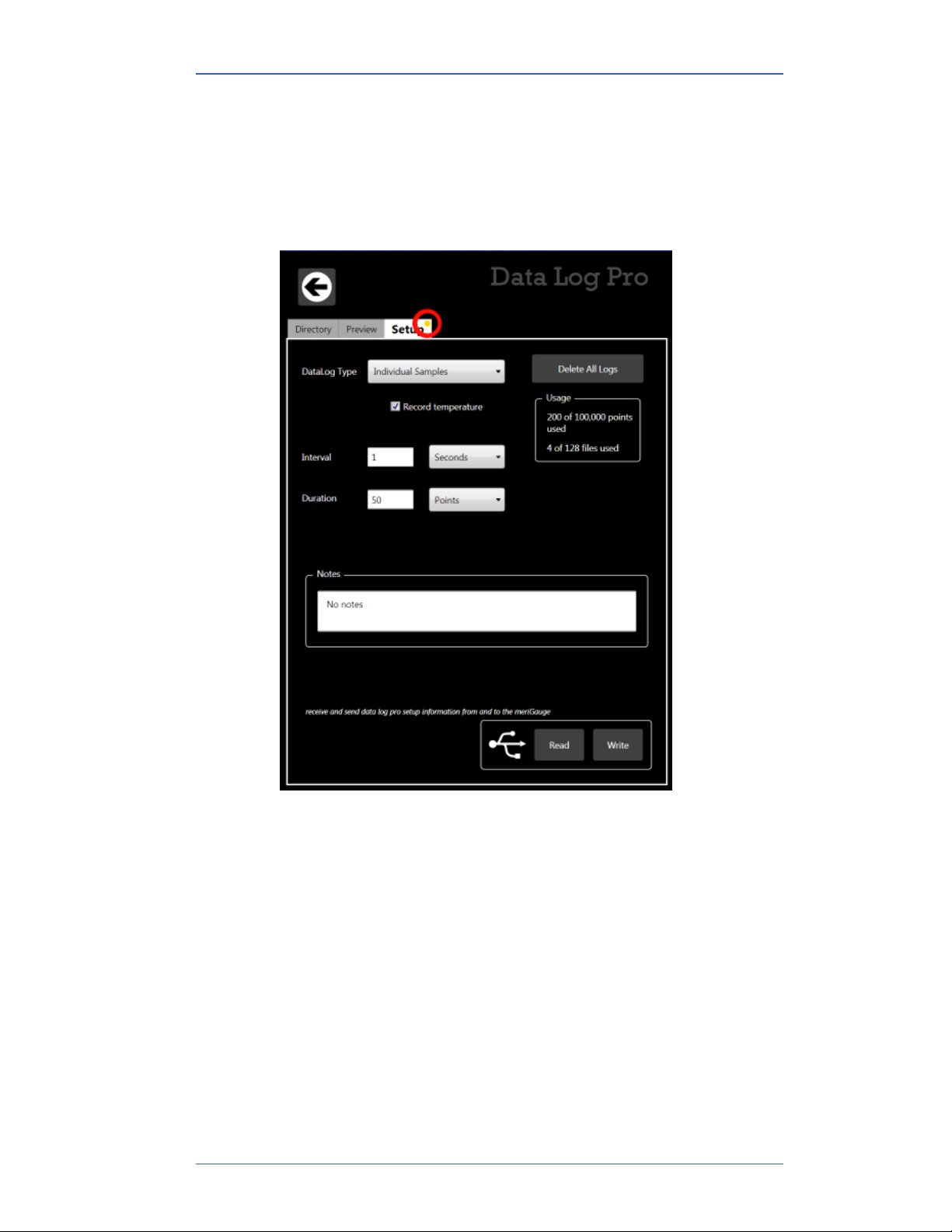
Watch for a yellow dot on an active tab
▪ A yellow dot appears on a tab in HHP400 Suite to indicate that
you have made changes to settings but you have not saved
them yet. See Figure 1 and Figure 2 below.
▪ You may click the Write button to save the changes you made.
Figure 1: Yellow dot on an active tab. See the red circle in the figure below.
User Manual HHP460 Smart Manometer with Altimeter & Air Speed Test
39 of 72
Page 40
M20013 REL-0000 (2103)
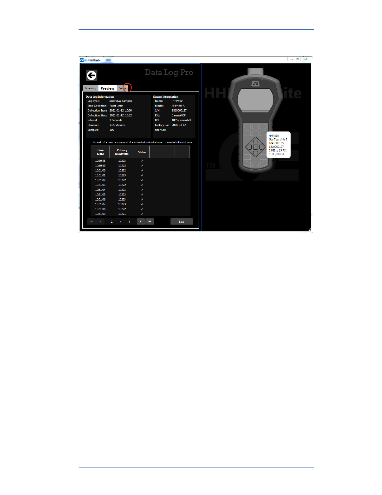
Watch for a yellow dot on an inactive tab
Figure 2: Yellow dot on an inactive tab. See the red circle in the figure below.
Year-Month-Date format
▪ The HHP400 Suite application displays the date in year-
month-day format.
▪ For example: 2016-04-22 (YYYY-MM-DD).
Hours:Minutes:Seconds format
▪ The HHP400 Suite application displays the time in 24-hour
format.
▪ You may choose from Time Zones:
Universal Coordinated Time (UTC) US - Arizona -7:00
US - Eastern -5:00 US - Pacific-8:00
US - Central -6:00 US - Alaska -9:00
US - Mountain -7:00 US - Hawaii -10:00
▪ For example: 15:05:45 UTC (hours:minutes:seconds).
User Manual HHP460 Smart Manometer with Altimeter & Air Speed Test
40 of 72
Page 41
M20013 REL-0000 (2103)
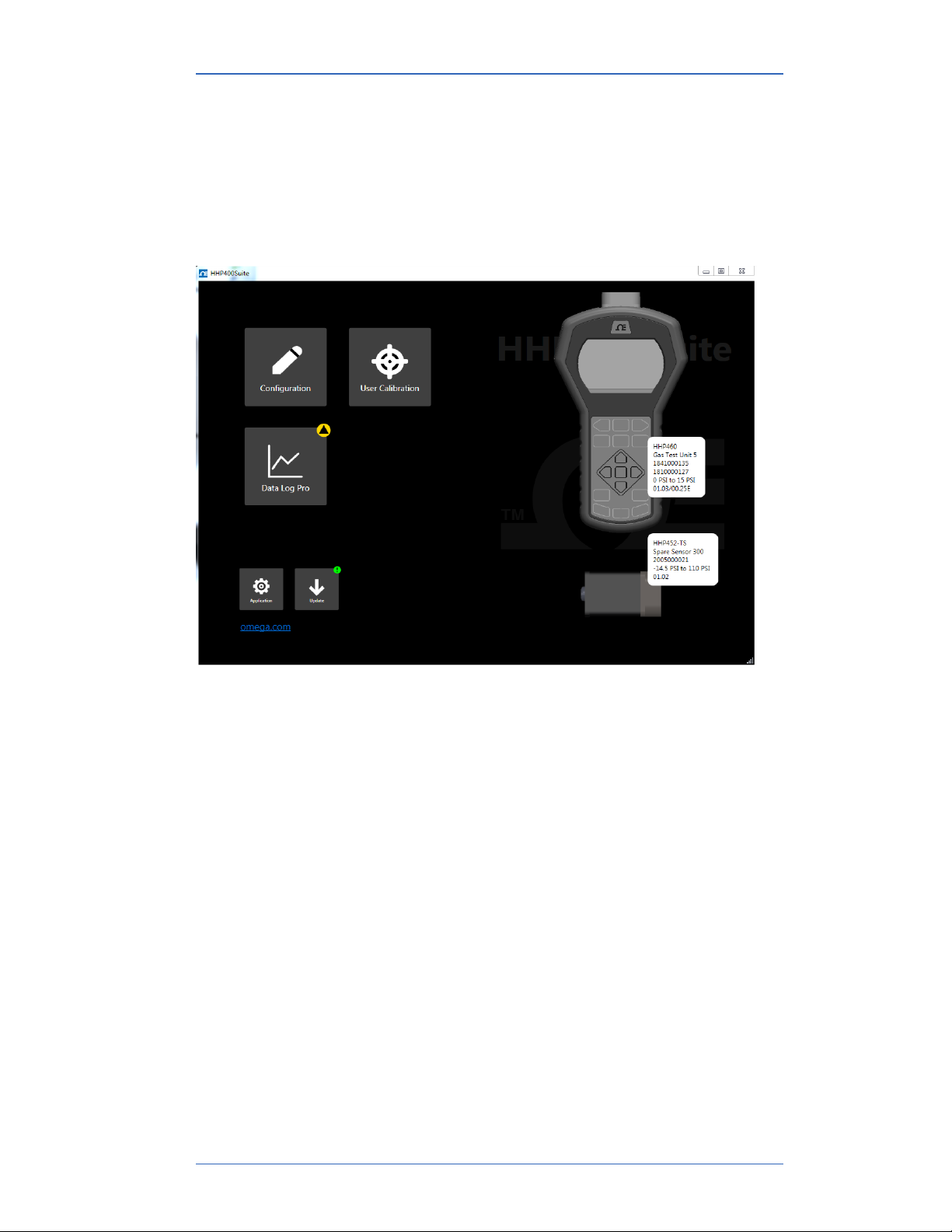
Connection status
Attached devices
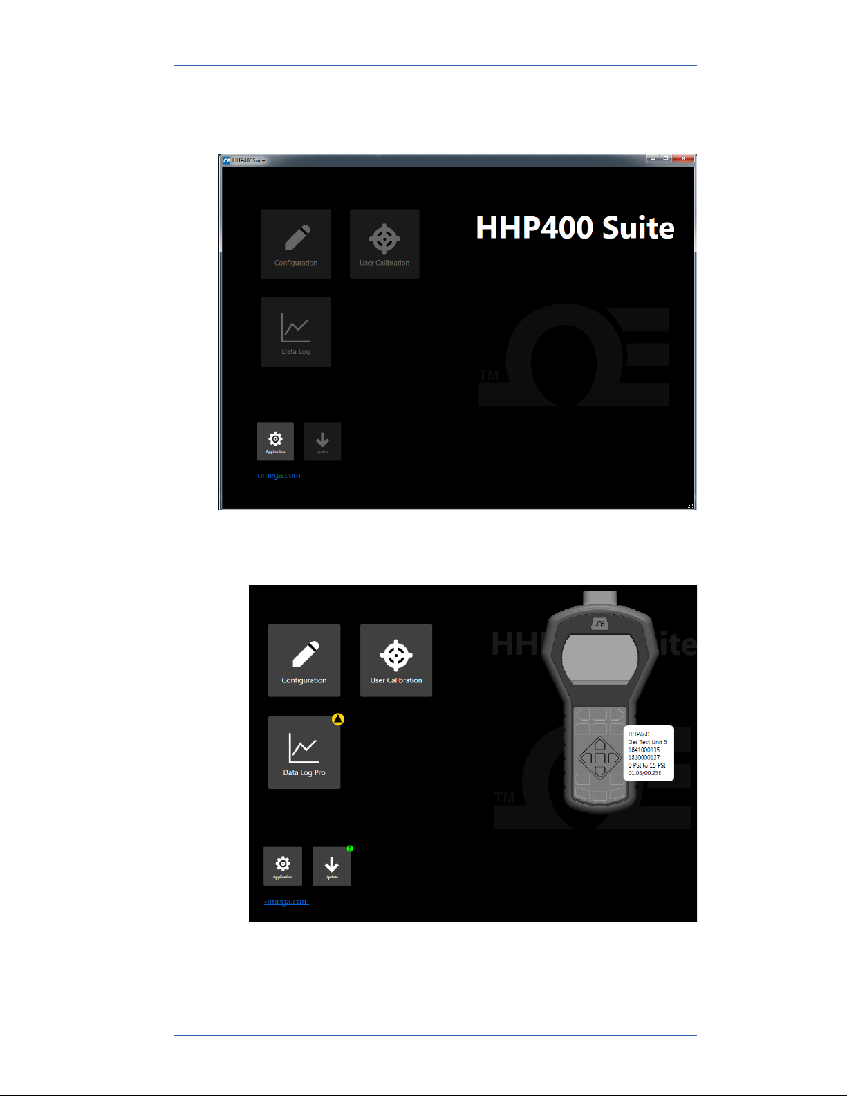
The HHP400 Suite application displays the figures of the Smart
Manometer and tethered sensor. Descriptions appear alongside
both of them. See the figure below.
User Manual HHP460 Smart Manometer with Altimeter & Air Speed Test
41 of 72
Page 42
M20013 REL-0000 (2103)
No attached devices
The HHP400 Suite application displays no figure of devices on the
right side. See the figure below.
No tethered sensor attached
Notice the figure of the Smart Manometer and description. See the
figure below.
User Manual HHP460 Smart Manometer with Altimeter & Air Speed Test
42 of 72
Page 43
M20013 REL-0000 (2103)
Configuration button
Overview of the Configuration button
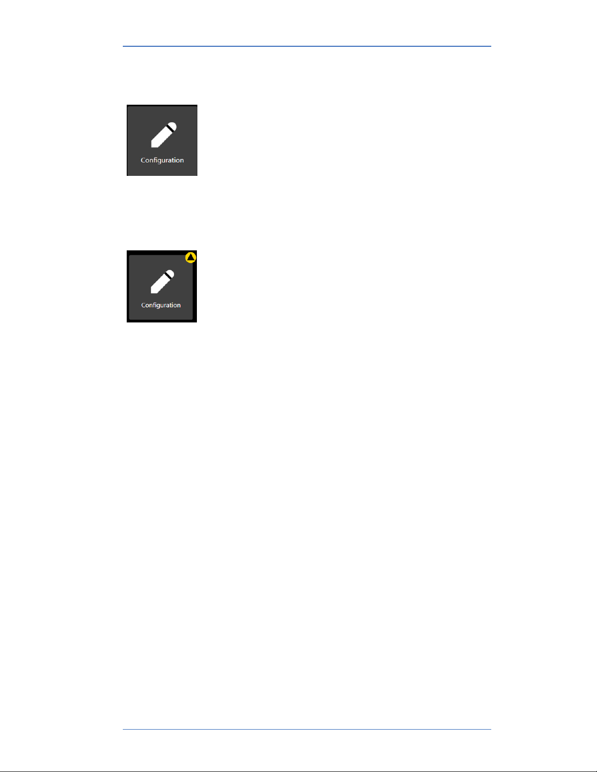
The Configuration button displays a window with two
tabs if a tethered sensor is attached:
• The first tab displays the Smart Manometer name or
the name you assigned to it.
• Optional: this second tab displays the tethered sensor
name or the name you assigned to it.
Note: These tabs oer you various settings to configure
the Smart Manometer and each sensor.
Notification about unsaved settings
It displays a yellow alert icon to indicate you have
changed a setting and you have not yet saved the setting.
Passwords
Overview of passwords
Passwords are never required to use a Smart Manometer or any
sensor.
▪ The passwords are turned o when the Smart Manometers
and sensors are shipped.
▪ Each device can have its own unique 16-character password.
You may use from 1-16 characters: letters, numbers, or
symbols, and uppercase and lowercase.
▪ An internal sensor and a tethered sensor have their own
separate passwords.
▪ Each device can have its password turned on or turned o
independently from any other tethered sensor.
▪ HHP400 Suite retrieves the passwords stored on the devices.
User Manual HHP460 Smart Manometer with Altimeter & Air Speed Test
43 of 72
Page 44

M20013 REL-0000 (2103)
HHP400 Suite uses the password
If you choose to select the Password Required For Future
Access, then HHP400 Suite requests a password for the following
actions:
▪ To modify a configuration.
Note: This action includes writing to or reading from a device.
▪ To update the firmware on a device or the application.
▪ To calibrate a device.
▪ To access the Setup tab of Data Log Pro.
HHP400 Suite remains unlocked
▪ Once HHP400 Suite accepts a password for one of those
actions, the device remains unlocked until it is disconnected
from HHP400 Suite.
▪ If you enter the password on one window, HHP400 Suite
unlocks that Smart Manometer or sensor on its other windows
as well.
Data Log Lite has no password
HHP400 Suite does not use a password for Data Log Lite since it
cannot make any changes to the device.
Request a recovery password from Omega
Forgot the password for a device or sensor?
▪ If you forget a password, contact Omega to generate a
recovery password for you to unlock the device.
▪ A recovery password disables the password until you create a
new password.
▪ You must have the serial number of the device or sensor to
request a recovery password.
▪ Call 1-800-826-6342 or send an e-mail to [email protected].
Recovery password valid for one date
When you call Omega to generate a recovery password, you may
select a date that is convenient for you. If you do not specify a
date, the request date is used.
User Manual HHP460 Smart Manometer with Altimeter & Air Speed Test
44 of 72
Page 45

M20013 REL-0000 (2103)
Common features for a Smart Manometer and sensor(s)
The Names field
You can assign your own company designations to each device.
As Left / As Found Configuration Report button
▪ You can review a summary of the configuration of the Smart
Manometer or sensor when it is first connected and the
changes you made.
▪ The As Found / As Left Report cannot report changes made
in HHP400 Suite unless you save those new configurations to
the device.
Read and Write Configurations
▪ Read and Write refer to reading configuration data from a
Smart Manometer or sensor or writing new data to them.
Save your configuration changes before you click the Read
button. After you click the Read button, all changes on-screen
are replaced with the configuration that is on the device.
Configuring devices
Sync PC time to Gauge
▪ Click to update the Smart Manometer time and date with your
computer.
▪ The LCD display and data logging use this time and date.
Timeouts
▪ Backlight.
▪ Auto O (Automatic O).
Display Functions
▪ Min/Max.
▪ Accuracy.
▪ Tare .
▪ Average.
▪ Rate of Change.
▪ Relief Valve Test.
▪ Time & Temp.
▪ Data Log.
▪ Allow zero adjust (Ø).
▪ Leak Test.
User Manual HHP460 Smart Manometer with Altimeter & Air Speed Test
45 of 72
Page 46

M20013 REL-0000 (2103)
Configuring sensors
Enabled Units
Select or deselect measurement units to view them on the Smart
Manometer. They are saved on each sensor.
▪ The All button selects all measurement units.
▪ The None button deselects all measurement units.
▪ You must select at least one unit before you can Write to the
sensor.
Two User Defined Units
You can define the Name, Multiplier, Oset, and Function for two
non-standard or unsupported display units.
Note: Flow type does not use Oset.
Note: (multiplier × PSI) + Oset = the displayed value for linear
type.
Damping
No settings on the Smart Manometer
You cannot set the Damp Rate on the Smart Manometer. You have
to click the Configuration button in HHP400 Suite to change the
Damp Rate.
Damping rate
Select a Time Constant: 1 second, 2 seconds, 4 seconds,
8seconds, or 16seconds.
▪ When set for 4 second time constant, it takes 4 seconds
from the time of the step change until the Smart Manometer
displays the full value of the new pressure.
Damping types
Select a Damp Type: Exponential, Smart Quick, Smart Normal, or
SmartSlow.
▪ Use adjustable Exponential type damping to steady the
display when you measure pulsating pressure or flow.
▪ Exponential damping displays approximately 70 % of a step
change in pressure at the next display update.
User Manual HHP460 Smart Manometer with Altimeter & Air Speed Test
46 of 72
Page 47

M20013 REL-0000 (2103)
User Calibration button
The User Calibration button displays options to calibrate
the sensor.
The User Calibration button displays a yellow alert icon
to indicate you have changed a setting and you have not
yet saved the setting to the Smart Manometer.
User Calibration: For authorized personnel only
What does “Calibration Enabled” refer to?
▪ With a check mark in the box, Calibration Enabled displays the
Live Reading with your current user calibration applied.
▪ Without a check mark in the box, it displays Live Reading
without your user calibration.
Restore Factory Defaults
This button clears your user calibration from the sensor.
Choose Calibration Unit
▪ Select the calibration reference units.
▪ This does not aect or depend on the configuration units.
Begin button…Apply button
1. Click Begin.
2. Select the point.
3. Apply reference pressure within the range shown.
4. Enter the reference value.
5. Save the point.
6. Repeat steps 2-5 until you are done. (You have to change at
least one point.)
7. Click the Apply button.
User Manual HHP460 Smart Manometer with Altimeter & Air Speed Test
47 of 72
Page 48

M20013 REL-0000 (2103)
Customer calibration
You can calibrate the manometer in the field for
1. Zero.
2. Span.
3. Linearity.
The customer calibration does not replace the Factory Lab
Calibration Procedure. It is intended to correct the curve fit if the
actual sensor characteristics change slightly over time.
For sensors up to 200 psi, Omega recommends a ± 0.0015 % of
reading deadweight tester. For sensors 200 psi and above, a ±
0.0030 % of reading deadweight tester is recommended. Note that
AI type sensor requires absolute referenced deadweight testers or
standards for field calibration. The options are:
1. 2-point (within upper 50 % of FS)
2. 5-point (nominal values of 0 %, 25 %, 50 %, 75 % and 100 % of
FS).
3. Restore factory default calibration.
For the 5 Point calibration, points 2, 3 and 4 can be adjusted
within ± 1 % of reading around the nominal values. Point #5 can
be adjusted within -1 % of reading around nominal. Point #1 is
fixed.
The unit can only be calibrated if the calibration points are within
5 times the accuracy of the original factory calibration
For example: at 0.05 % accuracy, the point limit is ± 0.25 % of
FS.
If the calibration procedure generates a new value outside this
limit the procedure fails. In this case the unit would need to be
returned to the factory for service.
After a calibration has been performed (either 2-point or
5-point), the sensor uses only that calibration. To turn on another
calibration type, you must first Restore Factory Defaults and then
choose another calibration method.
User Manual HHP460 Smart Manometer with Altimeter & Air Speed Test
48 of 72
Page 49
M20013 REL-0000 (2103)
Data Log button
Overview of Data Log buttons
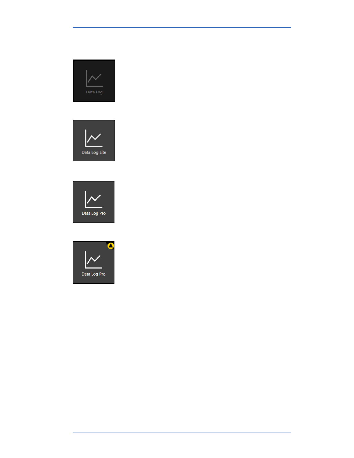
Data logging displays three dierent buttons depending
on what you order or on what you add-on at a later time.
The Data Log button is always unavailable until the USB
cable is attached to the computer with HHP400 Suite.
Data Log Lite
The Data Log Lite button displays when you attach a
Smart Manometer. Data Log Lite is the free version of
data logging. It has no options.
Data Log Pro
The Data Log Pro button displays when Data Log Pro
is activated on the Smart Manometer that is attached to
HHP400 Suite.
Data Log Pro alert
The button displays a yellow alert icon to indicate you
have changed a setting and you have not yet saved the
setting to the Smart Manometer.
User Manual HHP460 Smart Manometer with Altimeter & Air Speed Test
49 of 72
Page 50

M20013 REL-0000 (2103)
Data Log Lite
Preview tab
Preview the data log
The Preview tab displays the first 10 samples so you can confirm
the data to save. If you have fewer than 10, it displays all of your
samples.
Status and pressure for logs
The Status symbols for pressure and temperature.
The symbol corresponds to readings that are within the
calibrated range.
▪ The ⇵ and ⨯ symbols indicate an abnormal condition.
▪ The ⇵ symbol indicates readable data.
▪ The ⨯ symbol indicates dashes and no readable data.
The Pressure
The pressure indicates the reading at each 15-second interval in
the data set.
The Temperature
▪ The Omega Tethered Sensors displays when it is attached
(pressure or temperature).
▪ Temperature displays only when the Omega Tethered Sensors
RTD is attached.
User Manual HHP460 Smart Manometer with Altimeter & Air Speed Test
50 of 72
Page 51

M20013 REL-0000 (2103)
TSV file format
Overview
Configuration, Data Log Lite, and Data Log Pro provide you with
the option to save Configuration Reports and Data Log files in
TSV file format.
Two ways to open TSV files
Double click a TSV file
Double click a TSV file in Windows Explorer and if it opens in a
spreadsheet application, then you do not need to do anything
additional.
Examples of spreadsheet applications: Microsoft Excel,
Google Sheets, and OpenOice Calc.
Drag and drop a TSV file into a spreadsheet
Drag and drop TSV files to open them. The following steps are
similar for these spreadsheet applications: Microsoft Excel,
OpenOice Calc, and Google Sheets.
1. Open File Explorer (Windows 8 and 10). Keep File Explorer
small enough to see Excel in the background.
Note: Depending on which version of Windows you have, File
Explorer may be known as Windows Explorer, File Manager, or
My Computer.
2. Open Excel. It can have a blank spreadsheet or an existing
spreadsheet. Drag and drop creates a new spreadsheet.
3. Switch to File Explorer and navigate to the location where you
saved the TSV file.
4. Select the file and drag-and-drop it in the middle of the blank
spreadsheet.
5. Save it as an Excel file.
User Manual HHP460 Smart Manometer with Altimeter & Air Speed Test
51 of 72
Page 52
M20013 REL-0000 (2103)
Directory tab
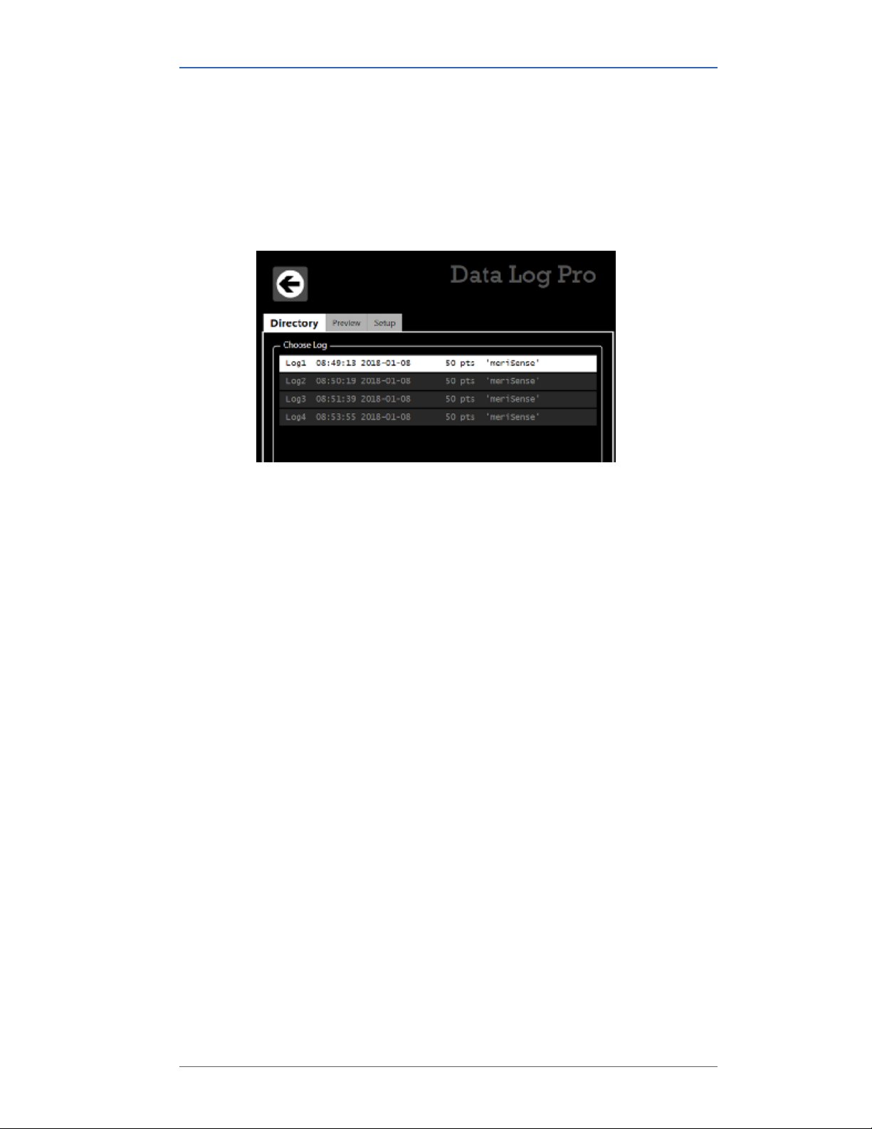
View the list of logs on the Smart Manometer
The Directory tab displays all the logs in the memory of the
connected Smart Manometer. Two ways to open a log:
▪ Double click a log to open it in the Preview tab.
▪ Or, you may select a log from the list and click the Preview tab
to view it.
User Manual HHP460 Smart Manometer with Altimeter & Air Speed Test
54 of 72
Page 53
M20013 REL-0000 (2103)
Preview tab
Overview of the Preview tab
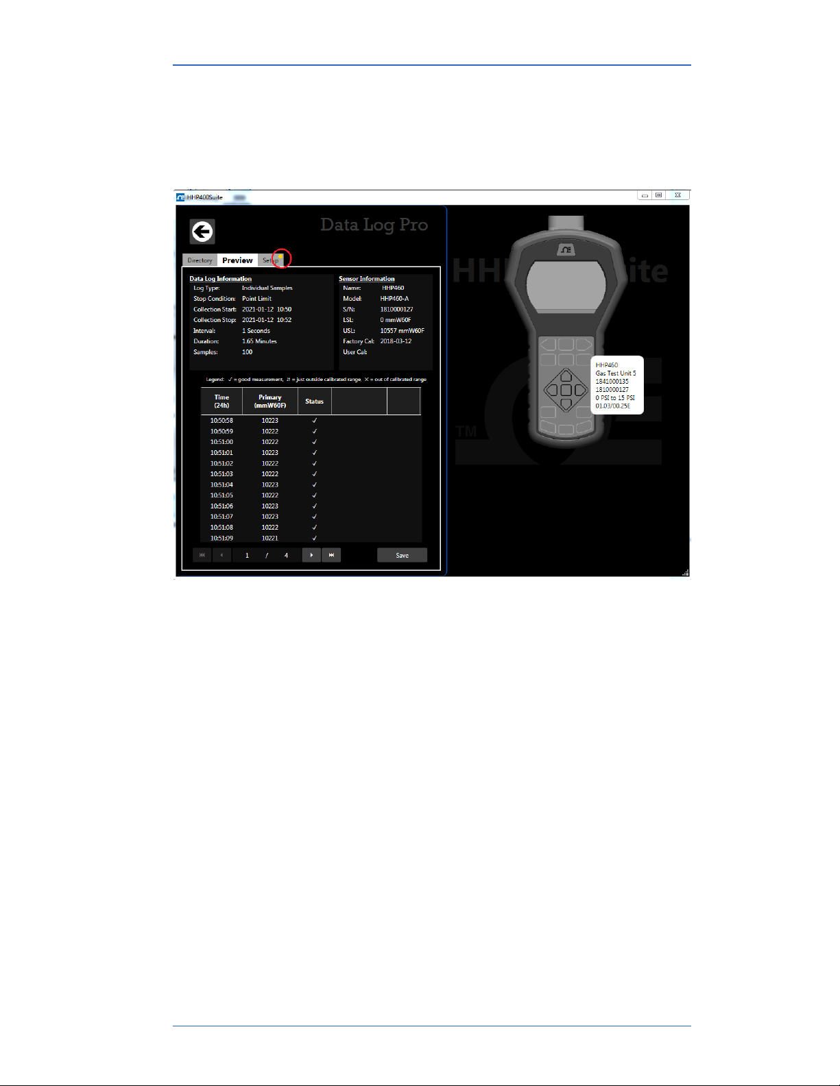
When you double click a log in the Directory tab, the Preview tab
opens.
The Preview tab contains seven areas of information:
1. Data Log Information list.
2. Sensor Information list.
3. Notes.
4. Legend.
5. Samples table.
6. Navigation bar.
7. Save button.
User Manual HHP460 Smart Manometer with Altimeter & Air Speed Test
55 of 72
Page 54

M20013 REL-0000 (2103)
Details about the Preview tab
1. Data Log Information list
A description of items in this list:
1. Log type indicates the type that was selected in the Setup tab
when the log was created.
2. Stop condition indicates why the log stopped.
List of stop conditions: Manual Stop, Data Complete, Time
Limit, Point Limit, Storage Limit, Low Power, Sensor Removed,
PC Connection, or Sensor Error
3. Collection Start indicates the day and time the log began.
4. Collection Stop indicates the day and time the log ended.
5. Interval is how often data is saved but the interval does not
display with the On Demand option.
6. Duration displays how long the log actually recorded data.
This may or may not be the Duration you selected in the Setup
tab. Check the Stop condition.
7. Samples indicate the number of readings in the log. They
reflect how many data points were saved.
2. Sensor Information list
▪ All information in this list was retrieved from the internal
sensor (and from an Omega Tethered Sensors if one was
attached) at the time the Smart Manometer recorded this
particular log.
3. Notes
▪ Any information that displays here comes from the text you
enter in the Notes box in the Data Log Pro Setup tab.
User Manual HHP460 Smart Manometer with Altimeter & Air Speed Test
56 of 72
Page 55

M20013 REL-0000 (2103)
4. Legend for the status columns
The samples table has two columns for Status. The legend
provides three symbols to indicate the level of confidence for
pressure or temperature measurements.
1. The symbol corresponds to readings that are within the
calibrated range.
2. The ⇵ and ⨯ symbols indicate an abnormal condition.
3. The ⇵ symbol indicates readable data but it is out of range.
4. The ⨯ symbol indicates dashes on the Smart Manometer and
no readable data.
6. Navigation bar
▪ This bar provides you with buttons to jump to the first log or to
the last log.
▪ The bar also provides you with buttons to navigate to the
previous log or next log.
▪ The numbers in the bar indicate which log out of the total
number of logs on the Smart Manometer that you are currently
viewing.
7. Save button
Click the Save button on the right side and the Save As box
appears. You can save the file in two file formats:
▪ PDF.
▪ TSV.
User Manual HHP460 Smart Manometer with Altimeter & Air Speed Test
57 of 72
Page 56

M20013 REL-0000 (2103)
Setup tab
Overview of the Setup tab
▪ The Setup tab lists parameters you may change. It gives you
usage statistics and it displays three action buttons.
▪ A yellow dot appears on this tab after you changed a setting
and have not saved it.
Parameter Choices
Four data logging types
1. Individual Samples refers to actual measurements taken at
fixed intervals.
2. Average only refers to average measurements over the
intervals you selected. It takes measurements every 200 ms.
3. Average with peaks refers to average measurements over
the intervals you selected. It also saves the maximum and
minimum measured values during the interval you saved. It
takes measurements every 200 ms.
4. On Demand refers to manually recording actual
measurements rather than at fixed intervals.
Interval types
You can select Seconds, Minutes, or Hours from a drop-down
menu and enter a number.
Duration types
▪ You can select: Minutes, Hours, Days, Forever, or Points and
enter a number.
▪ Selecting Forever makes the number box disappear.
Note: Forever is limited by the remaining number of points on
the Smart Manometer. Look for these numbers on the Usage box
to the right of Interval.
Notes edit box
Notes you enter in this edit box appear in the Preview tab, the TSV
file, and the PDF file. This field is limited to 64 characters.
User Manual HHP460 Smart Manometer with Altimeter & Air Speed Test
58 of 72
Page 57

M20013 REL-0000 (2103)
Usage statistics
Usage presents the amount of memory available on the Smart
Manometer for data logging in two ways:
1. The number of data points used out of a maximum of 100 000.
2. The number of logs used out of a maximum of 128.
Delete All Logs
This button deletes all the logs on the Smart Manometer. This
does not aect the files you saved to the computer in the Preview
tab.
Note: If the Smart Manometer has a password, then clicking this
button requires you to enter a password. This password was
created in the Configuration tab for a sensor.
Read
Write
Save your configuration changes before you click the Read button.
After you click this button, all changes on-screen are replaced
with the configuration that is on the Smart Manometer.
Note: If the Smart Manometer has a password, then clicking this
button requires you to enter a password. This password was
created in the Configuration tab for internal sensor.
Press this button, Data Log Pro reads the parameters from the
Smart Manometer and displays them in the Setup tab.
This button remains unavailable until you make a change in
the Setup tab. It saves the new setup parameters to the Smart
Manometer and overwrites the parameters stored on the Smart
Manometer.
Note: If a sensor has a password, then clicking this button
requires you to enter a password. This password was created in
the Configuration tab.
User Manual HHP460 Smart Manometer with Altimeter & Air Speed Test
59 of 72
Page 58
M20013 REL-0000 (2103)
Application button
Overview
The Application button displays a window with three
sections about the HHP400 Suite application:
• About.
• Available Update.
• Language Selection.
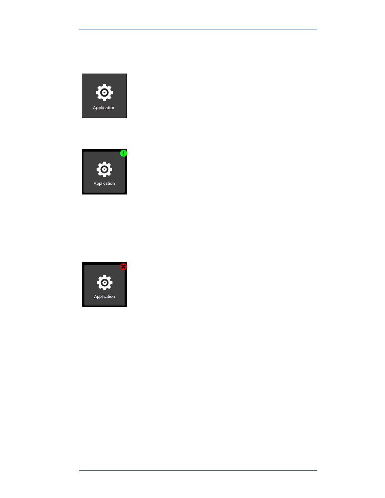
Application notifies you of available updates
It displays a green alert icon with an exclamation mark to
indicate an Available Update. After clicking this button, it
displays the following message:
“PLEASE BE ADVISED! If you choose to install the
update at this time, you will lose unsaved configuration
information or data log setup changes. Be sure to save
that information to a file or Write it to the connected
device.”
Application notifies you of no internet connection
It displays a red alert icon with an “x” to indicate:
“There is no connection to the update server. This is
usually caused by the PC not having internet connectivity
or the server may be temporarily unavailable.”
User Manual HHP460 Smart Manometer with Altimeter & Air Speed Test
60 of 72
Page 59
M20013 REL-0000 (2103)
Update button
Overview
The Update button displays a window with multiple
sections:
• The first section alerts you to updates for the sensor
and the Smart Manometer.
• The second section alerts you to updates for each
sensor that you attach to the Smart Manometer.
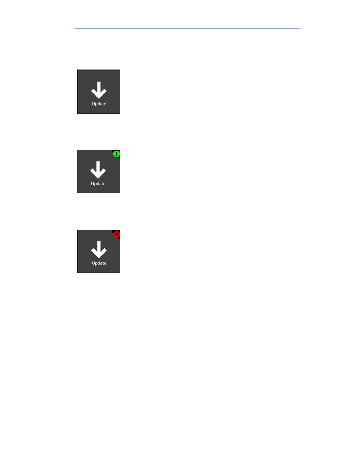
Update notifies you of available updates
It displays a green alert icon to indicate an update is
available for the firmware in the sensor or the Smart
Manometer.
Update notifies you that you have no internet connection
It displays a red alert icon to indicate:
“There is no connection to the update server. This is
usually caused by the PC not having internet connectivity
or the server may be temporarily unavailable.”
User Manual HHP460 Smart Manometer with Altimeter & Air Speed Test
61 of 72
Page 60

M20013 REL-0000 (2103)
Omega Tethered Sensors: type and range
Omega Tethered Sensors
Model number Pressure range
Absolute Isolated (AI)
HHP-A psi to psi
HHP-B psi to psi
User Manual HHP460 Smart Manometer with Altimeter & Air Speed Test
62 of 72
Page 61

M20013 REL-0000 (2103)
Omega Tethered Sensors: type and range
Omega Tethered Sensors
Model number Pressure range
Dierential Non-Isolated (DI)
HHP-A-TS - psi to psi
HHP-B-TS - psi to psi
HHP-K-TS -. psi to psi
HHP-L-TS
HHP-C-TS
Compound Isolated (CI)
HHP-D-TS –. psi to psi
HHP-T-TS –. psi to psi
HHP-U-TS –. psi to psi
HHP-V-TS –. psi to psi
HHP-W-TS –. psi to psi
HHP-X-TS –. psi to psi
HHP-Y-TS –. psi to psi
HHP-Z-TS –. psi to psi
Absolute Isolated (AI)
HHP-Q-TS psi to psi
HHP-I-TS psi to psi
HHP-R-TS psi to psi
-. psi to psi
-. psi to psi
User Manual HHP460 Smart Manometer with Altimeter & Air Speed Test
63 of 72
Page 62

M20013 REL-0000 (2103)
Pressure measurements
▪ Accuracy Specification
▪ ± (0.02 % of FS + 0.005 % of Rdg) from 0% to 110% of FS.
▪ For Compound sensors only:
▫ Vacuum ± (0.02 % of FS)
▫ Vacuum = -14.5 psi
▪ Accuracy statements include the combined eects of linearity,
repeatability, hysteresis, and temperature over the specified
operating temperature range.
▪ Warm up time: 5 minutes.
▪ You should zero the sensor at working ambient temperature
before using it.
User Manual HHP460 Smart Manometer with Altimeter & Air Speed Test
64 of 72
Page 63

M20013 REL-0000 (2103)
Overrange limit
▪ Overrange pressure or temperature means the value is outside
the calibrated upper or lower range.
▪ Above 100 %, the red backlight turns on automatically.
▪ Above 120 %, the red backlight turns on and displays OVER
RANGE in place of pressure reading.
Temperature
▪ Storage: –20 °C to 70 °C (–4 °F to 158 °F)
▪ Operating: –10 °C to 50 °C (14 °F to 122 °F)
Relative Humidity
▪ 95 % non-condensing.
Vibration
▪ 1 meter drop test.
Ingress specifications
▪ IP52 for the HHP400.
▪ IP54 for the Omega Tethered Sensors.
User Manual HHP460 Smart Manometer with Altimeter & Air Speed Test
65 of 72
Page 64

M20013 REL-0000 (2103)
Altitude specifications
Altitude MIN and MAX display values
▪ -2000.0 ft to 36 000.0 ft.
▪ -609.6 m to 10 972.8 m.
Indicated Air Speed specifications
Indicated Air Speed MIN and MAX display values
▪ 0 knots to 660 knots.
▪ 0 mph to 760 mph.
▪ 0 km/h to 1223 km/h.
Note: The barometric pressure value is captured when IAS
MPH (KNOTS or KM/H) appears on screen. It determines the
maximum indicated air speed.
Keypad
▪ Sealed membrane 16 domes.
User Manual HHP460 Smart Manometer with Altimeter & Air Speed Test
66 of 72
Page 65

M20013 REL-0000 (2103)
Media Compatibility
Pressure Types
▪ DN: Dierential pressure, non-isolated sensors for use with
clean, dry, non-corrosive gases only.
▪ DI: Dierential pressure, isolated sensors for use with gases
and liquids compatible with 316LSS and Viton O-rings
▪ CI, AI: Compound or Absolute pressure sensors for use with
gases and liquids compatible with 316LSS
Pressure Limits
▪ CI and AI units: 2x range
▪ DN units: 2x range when pressurized on high side only. 150
psi (10.5 kg/cm) static when applied to both sides of sensor
simultaneously.
▪ DI units: 1000 psi common mode, P1 (HI) only is 3x range, P2
(LO) only is 3x range or 150 PSI, whichever is less.
Battery Type
• 4 AA alkaline batteries of the same battery type.
User Manual HHP460 Smart Manometer with Altimeter & Air Speed Test
67 of 72
Page 66

M20013 REL-0000 (2103)
EMC compliance
Conformity to EN 61326-1:2016
This product has been evaluated to EN 61326-1:2016 the EMC
General requirements for electrical equipment for measurement,
control and laboratory use. This evaluation demonstrated that
when the product is exposed to Radiated Radio Frequency
energy in the frequency range 130-1000 MHz and 1.6-2.1 GHz, the
pressure and temperature readings may fluctuate beyond the
published tolerance of each respective value being measured. In
the event of such a phenomenon occurring, the operator should
move away from (or have removed) any source of strong RF
emissions such as radio transmitters, cell-phones, etc., and repeat
the measurement, or reconnect to a PC.
Electrostatic discharge (ESD)
This unit is sensitive to ESD discharges that may result in the
unit re-starting of the operating system, or interruption of a PC
connection. In the unlikely event of such an occurrence, users
should ensure they discharge any static charge they may be
carrying by touching a known grounded conductive surface prior
to operating the equipment .
User Manual HHP460 Smart Manometer with Altimeter & Air Speed Test
68 of 72
Page 67

M20013 REL-0000 (2103)
Dimensional specifications
Weight
▪ Smart Manometer: 1000 g (35.2 oz. or 2.2 lb.)
▪ Omega Tethered Sensors pressure module: 148 g or 0.33 lb.
Enclosure
Polycarbonate / ABS alloy.
User Manual HHP460 Smart Manometer with Altimeter & Air Speed Test
69 of 72
Page 68

M20013 REL-0000 (2103)
Maintenance and cleaning
Cleaning
▪ Clean the Omega Tethered Sensors and its cable with a soft,
damp cloth.
Prepare the Smart Manometer for storage
Remove the batteries to store the Smart Manometer
▪ We recommend that you remove the batteries from the Smart
Manometer if you are storing it for an extended time period.
▪ Follow the battery manufacturer’s instructions for storing your
batteries.
Store the Smart Manometer
▪ The recommended storage temperature for the Smart
Manometer is between: –20 °C to 70 °C (–4 °F to 158 °F).
User Manual HHP460 Smart Manometer with Altimeter & Air Speed Test
70 of 72
Page 69

M20013 REL-0000 (2103)
Register your product
We want you to get the most out of your purchase, and that starts
with a few, easy registration steps.
1. Go to www.Omega.com
2. In the Product Registration section, click Register a product.
Find downloads and documents
1. Go to www.Omega.com.
2. In the Technical Resources section, click Learn More.
3. Select one of these categories to find the files you need:
Product manuals | User Manuals and Quick Start Guides
Downloads | Applications (software), firmware, updates,
installation instructions
Certifications | Certifications and approvals
SDS (MSDS) | Safety Data Sheets
Control Drawings | Intrinsically Safe Drawings
User Manual HHP460 Smart Manometer with Altimeter & Air Speed Test
71 of 72
Page 70

M20013 REL-0000 (2103)
Help
If the device cannot be zeroed, calibrated, or is damaged, it must
be returned to the factory for servicing.
First ― Request a number
In the event that a device requires service and must be returned,
please contact Meriam using one of the methods listed in the
following table to request a Return Material Authorization (RMA)
number.
Method Provide the following information
Website http://www.omega.com
Complete the information online and submit the form.
Fax If you printed and completed the Service & Repair
Authorization form, then fax it to:
US and International Customers 1-800-826-6342
Email We need the following information in the email:
• Look on the product label to find the model
number & the serial number.
• Give a brief description of the problem.
• Send the e-mail to: [email protected]
Return Material Authorization
• Do not send any unit for repair unless you contacted Meriam
for a Return Material Authorization (RMA) number.
• Important: If you have not received this number and have not
clearly marked it on the package being shipped back, we will
return the unit at your expense.
• The Meriam Service & Repair Department will provide you
with this number when you complete the website form, fax or
e-mail your information.
• An RMA number must accompany all incoming packages to
insure proper tracking, processing, and repair work.
Questions? Contact Omega
Call ...................................................... (800) 826-6343
Email [email protected]
User Manual HHP460 Smart Manometer with Altimeter & Air Speed Test
72 of 72
 Loading...