

Page 1
User’s Guide
Shop online at
omega.com
e-mail: [email protected]
For latest product manuals:
omegamanual.info
SM
HHM660/701
Clamp Meters
Page 2

omega.com [email protected]
Servicing North America:
U.S.A.: Omega Engineering, Inc., One Omega Drive, P.O. Box 4047
Stamford, CT 06907-0047 USA
Toll-Free: 1-800-826-6342 (USA & Canada only)
Customer Service: 1-800-622-2378 (USA & Canada only)
Engineering Service: 1-800-872-9436 (USA & Canada only)
Tel: (203) 359-1660 Fax: (203) 359-7700
e-mail: [email protected]
For Other Locations Visit omega.com/worldwide
The information contained in this document is believed to be correct, but OMEGA accepts no
liability for any errors it contains, and reserves the right to alter specifications without notice.
Page 3

TABLE OF CONTENTS
Introduction. . . . . . . . . . . . . . . . . . . . . . . . . . . . . . . 3
Key Features . . . . . . . . . . . . . . . . . . . . . . . . . . . 3 –4
What’s in the Blister Pack . . . . . . . . . . . . . . . . . . . . 4
Product Overview . . . . . . . . . . . . . . . . . . . . . . . 4 –7
Safety Instructions . . . . . . . . . . . . . . . . . . . . . 7 – 10
Setup Instructions. . . . . . . . . . . . . . . . . . . . . . . . . 10
Install Batteries . . . . . . . . . . . . . . . . . . . . . . . . . 10
Operating Instructions. . . . . . . . . . . . . . . . . . 11 – 24
/MEGA Instructions. . . . . . . . . . . . . . . . . . 11 – 14
Ranging Options . . . . . . . . . . . . . . . . . . . . . . 11
Holding Readings . . . . . . . . . . . . . . . . . . . . . 11
Tracking Max and Min Readings . . . . . . 11 – 12
Making Relative Measurements . . . . . . . . . . 12
Disabling Auto Power Off (APO). . . . . . . 12 – 13
Using the Analog Bar Graph. . . . . . . . . . . . . . 13
Turning on the Backlight . . . . . . . . . . . . 13 – 14
Measuring AC or DC Current . . . . . . . . . . . 14 – 16
Measuring AC Inrush Current . . . . . . . . . . . . 15
Measuring Microamp Currents . . . . . . . 15 – 16
Measuring AC or DC Voltage. . . . . . . . . . . . 16 – 19
Using the Non-contact Voltage Detector 16 – 19
Measuring Resistance . . . . . . . . . . . . . . . . . . . . 20
Checking for Continuity . . . . . . . . . . . . . . . 20 – 21
Checking the Integrity of a Diode. . . . . . . . . . . . 21
Measuring Capacitance . . . . . . . . . . . . . . . . . . . 22
Measuring Frequency and Duty Cycle . . . . 22 – 23
Measuring Temperature . . . . . . . . . . . . . . . 23 – 24
Specifications . . . . . . . . . . . . . . . . . . . . . . . . 24 – 27
Operating & Maintenance Tips . . . . . . . . . . . . . . . 28
Warranty Information . . . . . . . . . . . . . . . . . . . . . . 29
Return for Repair Policy . . . . . . . . . . . . . . . . . . . . 30
2
Page 4

INTRODUCTION
Thank you for purchasing Omega Engineering
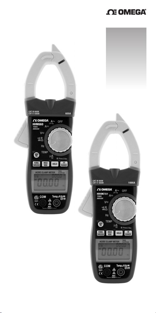
HHM660 or HHM701 Rugged Auto Ranging True RMS
AC/DC Clamp Meter. Please read this user’s manual
carefully and thoroughly before using the instrument.
Each meter combines the functions of a voltmeter and
a clamp-type ammeter. The meters are designed for
use in an industrial setting by HVAC/R contractors,
building maintenance technicians, MRO
(maintenance, repair and operations) personnel at
process and power plants, electricians and
electrical/electronic technicians.
The only difference between the HHM660 and HHM701
involves their current measurement range and
resolution. Where the HHM660 has a 0 to 600A
measurement range and a maximum current resolution
of 0.01A, the HHM701 has a 0 to 1000A measurement
range and a maximum resolution of 0.1A.
Both clamp meters are easy to use and ruggedly built.
Each meets the ETL CAT III 600V, CAT II 1000V safety
standard.
KEY FEATURES
• 16 functions, 49 ranges
• Measures AC/DC current, AC/DC voltage, resistance,
capacitance, frequency and duty cycle
• Also measures temperature from -58° to 1112°F
(-50° to 600°C) using included “K” type stem
thermocouple
• Uses beeper to verify integrity of diodes and check
circuits for continuity
• 0 to 200애A/2000애A AC/DC ranges for measuring
flame rod current with 0.1애A/1애A resolution using
included test leads
3
Page 5

• Built-in Non-Contact Voltage (NCV) detector with four
sensitivity settings and audible and visual alerts
• Large backlit digital LCD with two 6000-count
readouts for simultaneous display of real-time
current or voltage on primary readout and line
frequency on secondary readout
• Fast-response analog bar graph
• Bright LED work light
• Manual ranging and MIN/MAX display options
• Data HOLD and REL (zero) buttons
• INRUSH mode for measuring surge current during
motor startup
• 1.65 in. (42mm) jaw opening (largest in its class) for
conductors up to 550 MCM resists side torque
• Rugged housing can survive multiple drops onto
concrete from height of 5 ft. (1.6m)
• 20-minute Auto Power Off (APO) function can be
disabled
• ETL certified CAT III 600V, CAT II 1000V
• 3 year limited warranty
WHAT’S IN THE BLISTER PACK
The meter is supplied in a blister pack with a cavity in
the rear for a soft black nylon carrying pouch. Inside
the pouch are a set of double-insulated test leads
with screw-on alligator clips, a “K” type stem
thermocouple probe and plug adapter, 3 “AAA”
batteries and this user’s manual.
PRODUCT OVERVIEW
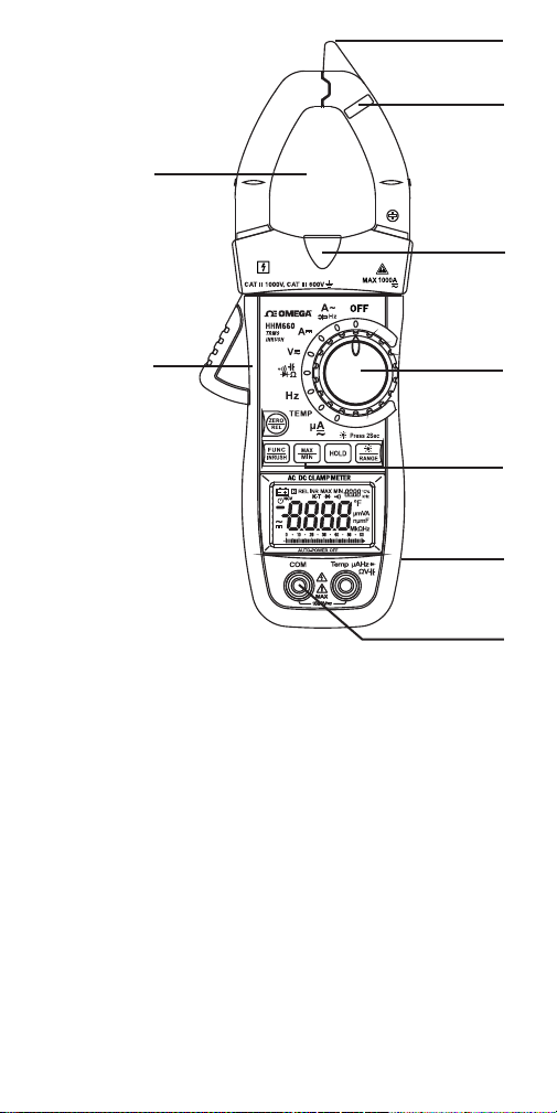
Fig. 1 shows the labels and positions of the controls,
indicators and physical structures of the HHM660 and
HHM701. Fig. 2 shows all possible indications on the
LCD of either unit. Familiarize yourself with the
functions and meanings of these controls, indicators
and connectors before moving on to the Setup
Instructions and Operating Instructions.
4
Page 6
1
2
8
3
7
Fig. 1.
The controls,
AUTO
AUTO
indicators and
physical structures
of the HHM660
and HHM701.
. Non-contact voltage (NCV) sensor
1
2
. NCV visual indicator
3
. LED work light
4
. Rotary function switch
5
. Multi-function buttons:
ZERO/REL
measurement baseline
measurement mode
—Used to 1)
, in which main readout shows
Reset DC current
to 0A, 2)
Enter relative
difference between real-time reading and stored
reading shown on secondary readout, 3)
meter’s Auto Power Off
function.
Disable
4
5
9
6
5
Page 7
FUNC/INRUSH
—1)
Selects among
resistance
measurement, capacitance measurement, diode
integrity and continuity check modes with rotary
function switch in position, 2)
between AC and DC
or position, 3)
measurement mode
position, 4)
Enters NCV sensitivity set mode
with rotary function switch in
Enters surge current
with rotary function in
Switches
pressed and held when powering on the meter.
MAX/MIN—Pressed once, enters Max/Min mode
Meter displays maximum value recorded during
current measurement session on secondary
readout.
minimum
Pressed twice, switches to display
value recorded during current
measurement session on secondary readout.
Pressed a third time, exits Max/Min
HOLD—Pressed once
, holds measured value(s)
(freezes main and secondary readouts).
, releases both readouts.
again
—
Pressed briefly
, enters manual ranging
mode.
Pressed
mode in broadest range. Each subsequent button
press switches to next-narrowest full-scale
measurement range. Pressing button in narrowest
range returns to auto ranging mode.
for >2 seconds, activates display backlight
held
Pressed and
(and LED work light if rotary function switch is in
or position).
6
. Test lead jacks
7
. Clamp jaw release
8
. Clamp jaw
9
. Battery compartment (on back)
if
.
6
Page 8
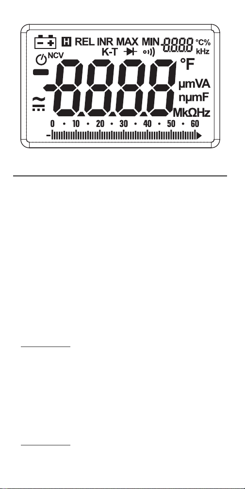
Fig. 2. All possible display indications
AUTO
SAFETY INSTRUCTIONS
To avoid possible electric shock or personal injury,
and to avoid damaging the meter or the equipment
under test:
• Do not use the meter in any way not detailed in this
manual or the meter's safety features may be
compromised.
• Before using the meter, inspect the case.
Do not use the meter if it is damaged. Look for
cracks or missing plastic. Pay particular attention to
the insulation around the connectors.
WARNING
•
insulation or exposed metal. Check the test leads
for continuity. Replace damaged test leads before
using the meter.
• Verify the meter’s operation by measuring a known
voltage. Do not use the meter if it operates
abnormally. Protection may be impaired. When in
doubt, have the meter serviced.
WARNING
•
voltage, as marked on the meter, between the
terminals or between any terminal and ground.
7
Warning
Inspect the test leads for damaged
Do not apply more than the rated
Page 9

•
WARNING
Do not measure voltages above 1000V
in Category III installations.
•
WARNING
Do not measure voltage when the
function switch points to the resistance (ohms),
current, capacitance or temperature settings. Never
measure current when the switch points to the
resistance (ohms), capacitance or temperature
settings.
• Use caution when working with voltages above
42VAC
, or 60VDC. These voltages pose a shock
RMS
hazard.
• Use the proper terminals, function, and range for all
measurements.
•
WARNING
Do not operate the meter around
explosive gas, vapor, or dust.
•
WARNING
When using the probes, keep your
fingers behind the finger guards. Do not touch the
metal probes of the test leads when making a
measurement.
• When making connections, connect the black (–)
test lead before connecting the red (+) test lead;
when disconnecting, disconnect the red (+) test
lead before disconnecting the black (–) test lead.
• Disconnect circuit power and discharge all highvoltage capacitors before measuring/testing
resistance, continuity, diodes, or capacitance.
• For all DC functions in both auto and manual
ranging mode, to avoid the risk of shock due to
possible improper reading verify the presence of
any AC voltages by first using the AC function. Then
select a DC voltage range equal to or greater than
the AC range.
• Before measuring current, turn off power to the
circuit before connecting the meter.
• Do not operate the meter with the case (or part of
the case) removed.
8
Page 10
• Use only three “AAA” batteries, properly installed in
the battery compartment, to power the meter. Do
not use rechargeable batteries.
• Replace the batteries as soon as the low battery
indicator “ ” appears. Operated with weak
batteries, the meter might produce false readings
that could lead to electric shock and personal injury.
• Remove the test leads from the meter before
opening the meter case or battery compartment.
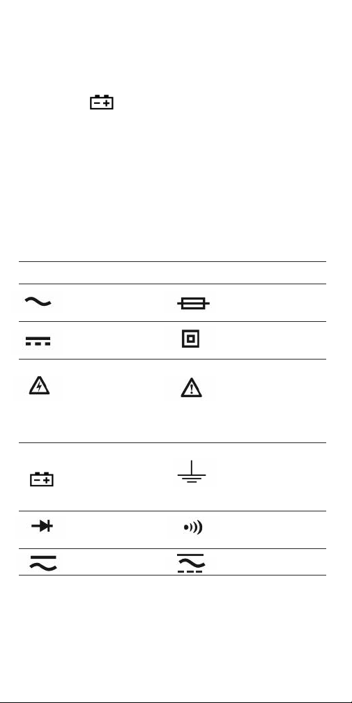
Electrical Symbols Used On the
Meter and In This Manual
Symbol Description Symbol Description
AC (Alternating Fuse
Current)
DC Double
(Direct Current) Insulated
Caution, risk of Risk of danger.
electric shock. Important
Hazardous information.
voltage. Refer to the
manual.
Battery
(Low battery) Earth ground
when shown
on display
Diode Continuity
Beeper
AC or DC AC/DC
9
Page 11

Symbol Description Symbol Description
Application and For measurements
removal from made on building
hazardous live equipment such
conductors as distribution panels,
permitted feeders and short
branch circuits, and on
lighting systems in
large buildings.
Auto Power Off
function
CAT IV
For measurements on
circuits connected
directly to the source of
power for a given building (for example, on the
cable to the power
transformer ahead of
a building’s circuit
breakers). Very high
levels of energy available at CAT IV level
make arc flash possible.
SETUP INSTRUCTIONS
INSTALL BATTERIES
The battery compartment of the HHM660/701 is
located at the back of the meter.
To open the compartment, use a small Phillips-head
screwdriver to remove the single screw securing the
battery compartment cover. Be careful not to lose the
small screw. Put the screw and the cover to the side.
Install the three supplied “AAA” batteries in the
battery compartment. Use the polarity marks
stenciled inside the compartment as a guide.
Replace the battery compartment cover and secure it
with the Phillips-head screw.
10
Page 12
OPERATING INSTRUCTIONS
OMEGA INSTRUCTIONS
The HHM660/701 provides several functions that can
be applied to measurements and displays of multiple
parameters.
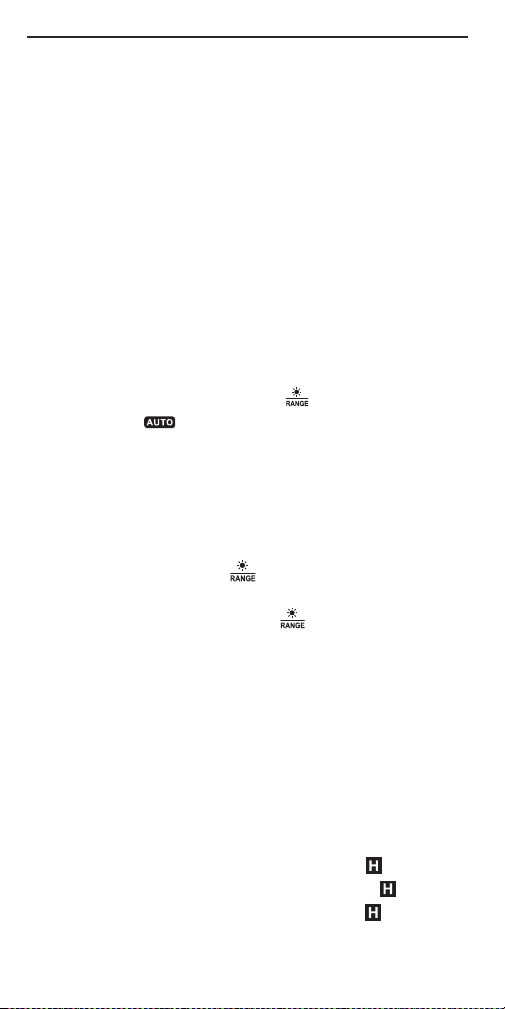
Ranging Options
chooses the measurement range that maximizes the
resolution of its current, voltage, resistance,
capacitance, frequency and temperature
measurements. The term
the left side of the LCD—indicates operation in auto
ranging mode.
To switch to manual ranging for any measurement
other than frequency, press the button once. This
will make the term disappear and cause the
meter to enter the broadest full-scale range available
for that parameter (see the Specifications section on
pp. 24 to 27 for a list of the measurement ranges
available for each parameter).
Once the meter is in manual ranging mode, each
subsequent press of the button will narrow the
full-scale range by an order of magnitude (a factor of
10). For example, pressing the button with the
meter operating in the 0 to 600애F full-scale manual
range will narrow the full-scale range to 0 to 60애F
(and improve measurement resolution). The next
press of the button will narrow the range to 0 to 6애F.
When the narrowest full-scale range has been
reached, the next press of the button will cause the
meter to re-enter Auto Ranging mode.
Holding readings
the values on both the primary and secondary
readouts and causes a reverse-type “H” ( ) to
appear on the top of the LCD. Pressing the button
again releases the hold and removes the .
Tracking Max and Min Readings
MAX/MIN
11
. By default, the meter automatically
AUTO
—in reverse type on
. Pressing the
HOLD
button “freezes”
. Pressing the
button once switches the secondary
Page 13

readout to show the
largest
value of the parameter
being measured since entering that measurement
mode. The primary display and the analog bar graph
below it will continue to show real-time readings.
Pressing the
MAX/MIN
the secondary readout to show the
button a second time switches
smallest
value of
the parameter being measured since entering that
measurement mode. The primary display and the
analog bar graph below it will continue to show realtime readings.
Pressing the
MAX/MIN
button a third time resumes
“normal” display operation, with different values in
the primary and secondary readouts.
When the
MAX/MIN
button is pressed, the meter will
automatically exit Auto Ranging mode and enter
Manual ranging mode using the full-scale range in
effect at that moment.
Making Relative Measurements
ZERO/REL
button during measurement of a current,
. Pressing the
voltage, resistance or capacitance freezes the value
being measured at that moment on the secondary
REL
readout. The term
LCD to indicate operation in this special mode. In
mode, the primary readout will show the
will appear on the top line of the
REL
difference
between ongoing measurements and the frozen value.
REL
mode is useful for tracking changes in dynamic
processes or deviations from baseline readings.
When the
REL
button is pressed, the meter will
automatically exit Auto Ranging mode and enter
Manual ranging mode using the full-scale range in
effect at that moment.
To exit
REL
mode and resume operation in “normal”
display operation, press the
ZERO/REL
Disabling Auto Power Off (APO
). By default, the meter
button again.
will automatically power itself off if no front-panel
buttons are pressed within any span of 20 minutes.
12
Page 14
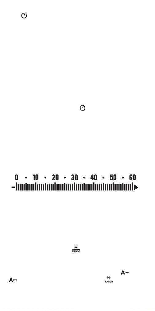
The icon on the left side of the LCD indicates that
the APO function is enabled.
Once the APO function has activated and powered the
meter off, you cannot reactivate the meter simply by
turning the rotary function switch to a different
position. You must either rotate the switch to the
OFF
position and then to another position, or press a
button—any button.
APO
To disable the
function, you must power on the
meter in a special way—by pressing and holding the
ZERO/REL
switch to a position other than
button while turning the rotary function
OFF
. If the meter is
powered on in this way, the icon will not appear.
If the meter is left unattended, it will remain powered
on until its batteries discharge (typically, several days
later).
Using the Analog Bar Graph
The bar graph at the bottom of the LCD (see below)
provides an analog representation of every
measurement shown in digital form on the primary
readout above it.
The key feature of the bar graph is its fast response
time. It can reflect a change in a measured value
10 times more quickly than the digital readout can.
Accordingly, it is useful for tracking parameters that
change very rapidly (a voltage or current, for
example).
Turning On the Backlight
Pressing and holding the button for at least
3 seconds turns on the LCD’s bright white backlight,
making measurements much easier to read in dark
spaces. If the rotary function switch is in the or
position, pressing and holding the button also
turns on the bright white LED work light at the base of
the clamp jaw (Fig. 1, Callout 3).
13
Page 15
To avoid having the backlight drain the meter’s
batteries, the backlight (and work light, if activated)
automatically extinguishes in 20 seconds.
MEASURING AC OR DC CURRENT
Warning
Before making current measurements, make certain
that all test leads are disconnected from the meter
terminals.
(1) Set the rotary function switch to the (AC
current) or (DC current) position to match the type
of current you wish to measure. The corresponding
or symbol will appear on the left side of the
LCD. Before measuring DC current, press the
ZERO/REL
measurement baseline to
button to reset the DC current
0A
.
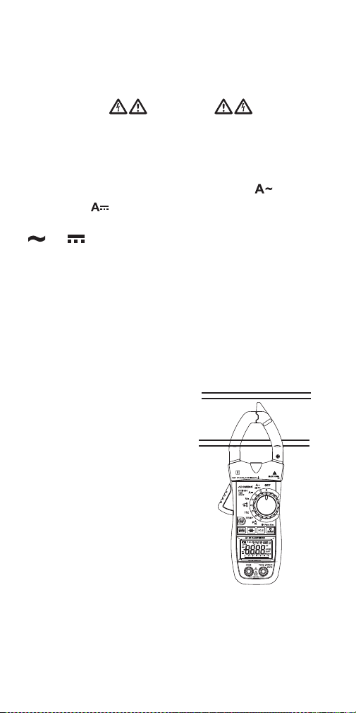
(2) Squeezing the clamp jaw release to open the jaw,
place it around the conductor whose current you wish
to measure. Be sure to enclose only one conductor
(see figure below). Enclosing both conductors of a pair
will produce a reading of 0.
Notes:
Clamp the jaw around one
conductor only.
Close the jaw completely.
Center the wire in the jaw
for highest accuracy.
When measuring DC currents,
observe the “+” polarity mark
AUTO
AUTO
on the right jaw to avoid
negative readings.
(3) Read the measured value(s) from the display.
During measurements of AC current, the primary
readout in the center of the LCD shows the measured
current value, while the secondary readout in the
upper right corner shows the frequency of the current.
14
Page 16

Notes:
A. Omega's HHM301 Flex Clamp Adapter (optional)
makes it possible to enclose a thick or hard-toreach conductor, a bundle of conductors, or a
busbar carrying up to 3000A. The accessory uses
induction to convert current readings to millivolt
values that can be displayed by the HHM660 or
HHM701. For more information or to order, visit
www.omega.com and enter “HHM301” in the
SEARCH box.
Measuring AC Inrush Current
To measure the inrush current
startup, press the
FUNC/INRUSH
function switch in the position. The term
of a motor during
button with the rotary
INR
will
appear on the top line of the LCD and the primary
readout will show the motor’s surge current (to a
maximum of 600A for the HHM660 and 1000A for the
HHM701). For this application, the current is measured
by the clamp jaw, after it has been placed around one
conductor of the motor’s power supply line.
To return to AC current measurement mode, press the
FUNC/INRUSH
button again.
Measuring Microamp Currents
The HHM660/701 provides two dedicated ranges
(0 to 200애A, and 0 to 2000애A) for measuring minute
amounts of AC or DC current (such as from a furnace
flame rod). For this application, the test leads are
placed in series with the device conducting the
current.
15
Page 17

To measure a microamp current:
1. Turn the rotary function switch to the 애A position.
2. Plug the red and black test leads into the red and
black jacks at the bottom front of the meter.
3. Connect the test leads in series with the device
whose current flow you wish to measure.
4. Read the measured current amplitude on the
primary readout.
MEASURING AC OR DC VOLTAGE
Do not measure voltage higher than 1000V. Doing so
may damage the meter’s internal circuitry. If the
voltage is over 1000V, the beeper will sound
continuously, indicating an over-range measurement.
(1) Set the rotary function switch to the position.
By default, when the switch is set to this position the
meter will measure AC voltage. To measure DC
voltage, press the
icon at the lower left of the LCD from to .
(2) Plug the red and black test leads into the red and
black jacks at the bottom front of the meter.
(3) Touch or clip the black test lead to the lowerpotential point of the circuit under test, and the red
test lead to the higher-potential point.
(4) Read the measured voltage on the display. If the
test leads are reversed, a minus sign will appear at
the left of the displayed value.
Using the Non-contact Voltage Detector
The NCV function provides a safe (non-contact) way
to check whether a line, cable or AC outlet is “hot”
(energized). At the tip of the clamp jaw (Fig. 1, Callout
1) is an NCV sensor that can detect from a short
distance the electromagnetic field created by AC
voltage. If voltage is detected, the meter produces
audible and visual alarms (a beeping sound, and a
Warning
FUNC/INRUSH
button to change the
16
Page 18

flashing white light behind a red lens near the tip
(Fig. 1, Callout 2)).
Even unloaded AC circuits generate electromagnetic
fields. Although these fields are extremely weak, their
constantly changing nature means that they generate
some current. A sensitive NCV detector can sense this
current via induction, in much the same way that a
sensitive radio receiver can sense weak radio waves.
NCV detectors cannot detect DC voltages, such as
those present in automotive electrical systems. In
addition, the HHM660/701 typically cannot detect
120VAC from a distance of more than 0.25 in.
(6.2mm), and never through a wall or metal conduit.
Unlike other NCV detectors with only one sensitivity
level—and therefore the ability to detect only one
range of voltages (typically 50 to 600VAC)—the
detector in the HHM660 and HHM701 has four
sensitivity levels. They were chosen to optimize
voltage detection over four practical ranges: 12 to
25VAC, 70 to 125VAC, 150 to 240VAC and
250 to 600VAC.
The ability to detect the presence of 12VAC in
noncontact fashion comes in very handy during
troubleshooting of branch circuits and process plant
and industrial automation systems and equipment
such as gas and water valves, fans, lights, relays,
inverters, solenoids and horns. 12VAC is also
commonly used to power hardwired commercial and
residential building doorbells/buzzers and
thermostats. Separately, the HHM660/701’s ability to
detect 480V using its lowest sensitivity range makes
troubleshooting and installing generators and
fluorescent lighting ballasts easier, faster and safer.
User-adjustable sensitivity does more than make the
NCV detector in the HHM660/701 more versatile. It also
improves the instrument’s performance. The value of
the detector’s highest sensitivity level (12 to 25VAC)
17
Page 19
is obvious: it allows non-contact detection of 12VAC,
an ability that most other NCV detectors lack.
However, the detector’s lower sensitivity levels, which
cover common AC power voltages, also have great
value, for the following reason.
Merely detecting the presence of 120VAC near a
bundle of wires does not tell you which wire of the
bundle is the “hot” wire; any of the wires could be
activating the alarms. The NCV detector in the
HHM660/701 can help you isolate the hot wire. This
application calls for turning down the sensitivity in
stages after the NCV detector senses voltage. As you
reduce sensitivity, at some stage only the energized
wire will produce a field strong enough to activate the
NCV’s alarms. In this way, the adjustable sensitivity of
the HHM660/701’s NCV detector takes the guesswork
out of identifying the “hot” wire of a bundle.
By default, powering on the HHM660/701 enables the
NCV function (indicated by the term NCV on the left
side of the LCD) and sets it to a sensitivity of 3. At this
level, the corresponding voltage detection range is 70
to 125VAC—optimum for detecting energized outlets
in the U.S.
To disable the NCV function or change its sensitivity
,
you must first power off the meter and then power it
back in special way—by pressing and holding the
FUNC/INRUSH
switch to a position other than
button while turning the rotary function
OFF
.
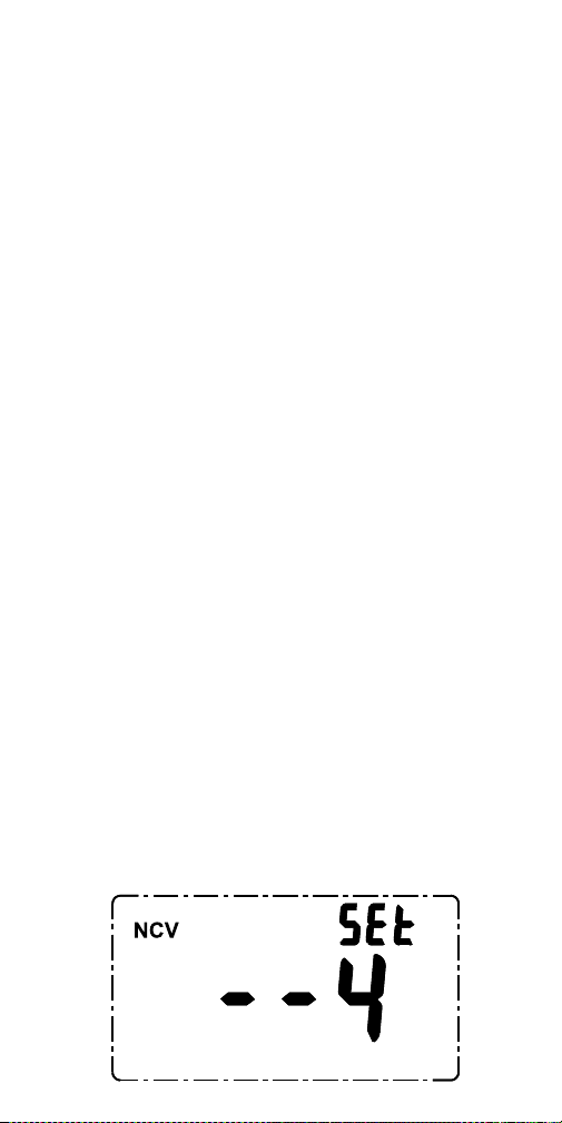
Powering on the meter in this way produces the
following display on the LCD.
18
Page 20

To change the NCV sensitivity level, press the
button one or more times. Pressing the button
once from a starting sensitivity of 4 changes the level
to 0, effectively disabling the NCV function. Pressing
the button an additional one, two or three times
changes the sensitivity level to 1, 2 and 3,
respectively.
Once you have determined which level of NCV
sensitivity suits your application, use the button
to set it to that level. After you disable the NCV
function or change its sensitivity level, you must then
HOLD
save the setting by pressing the
meter will remember this setting and resume
operation at that sensitivity level the next time it is
powered on, and even after a battery replacement.
The NCV detector in the HHM660/701 is designed to
indicate the presence of AC voltage with an amplitude
between 12VAC and 600VAC. Accordingly, do
assume that the absence of a positive indication
means that the circuit under test is de-energized (not
“hot”). Although they can cause shock and/or serious
personal injury, voltages below 12V may not be
detected by the HHM660/701. Whenever you have
reason to suspect that a line or outlet is “hot”,
confirm your suspicion by measuring the voltage of
the line or outlet using the test leads and with the
meter’s rotary function switch in the position.
To check whether a line, cable or AC outlet is “hot”
(energized), touch it with the tip of the clamp jaw or
bring the tip within 1/4 inch of it. If the beeper sounds
repeatedly and the LED flashes rapidly, the line or
outlet is energized.
Warning
button. The
not
19
Page 21
MEASURING RESISTANCE
Warning
To avoid electrical shock or damage to the meter
when measuring resistance or continuity in a circuit,
make sure power to the circuit is turned off and all
capacitors are discharged.
(1) Turn the rotary function switch to the position.
By default, when the switch is initially set to this
not
position with the test leads
plugged in, the
meter will automatically enter the 60MΩ range,
O.L
display
primary readout, and display the term
(indicating an open circuit) on the
MΩ
above
the right end of the bar graph at the bottom of
the LCD.
(2) Plug the red and black test leads into the red and
black jacks at the bottom front of the meter.
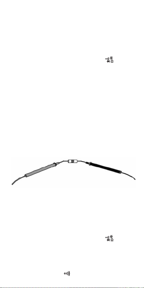
(3) Measure the resistance by touching or clipping the
tips of the leads to the desired test points of the
circuit or to the terminals of a component, as
shown below.
RED TEST LEAD
BLACK TEST LEAD
(4) Read the measured resistance on the display. If
the measured resistance value is greater than
O.L
60MΩ,
will appear on the primary readout.
The meter will take a few seconds to stabilize
when measuring resistances greater than 1MΩ.
CHECKING FOR CONTINUITY
(1) Turn the rotary function switch to the position.
Press the
FUNC/INRUSH
button once to select the
continuity check function. If test leads are not
plugged into the meter’s front-panel jacks, the
.OL
primary readout will show
, with the icon of a
continuity beeper ( ) above it.
20
Page 22
(2) Plug the red and black test leads into the red and
black jacks at the bottom front of the meter.
(3) Touch or clip the test leads to any two points of a
circuit. The resistance between those two points
will be shown on the primary readout. If the
resistance is <50Ω, the beeper will sound
continuously. If there is no continuity (an open
circuit or a resistance greater than 600Ω between
O.L
the two points),
will appear on the primary
readout.
CHECKING THE INTEGRITY OF A DIODE
(1) Turn the function switch to the position. Press
FUNC/INRUSH
the
button twice to select the diode
check function. If test leads are not plugged into
the meter’s front-panel jacks, the primary readout
O.L
will show
, with the icon of a diode ( )
above it.
(2) Plug the red and black test leads into the red and
black jacks at the bottom front of the meter.
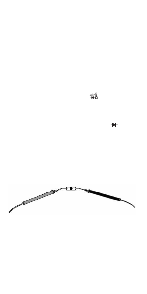
(3) Touch or clip the red test lead to the anode
(positive terminal) of the diode to be tested, and
the black test lead to its cathode (negative
terminal).
RED TEST LEAD
BLACK TEST LEAD
(4) Read the forward bias voltage value on the display.
A silicon diode typically has a forward bias voltage
of 0.7V. A germanium diode typically has a forward
bias voltage of 0.3V. A 0V reading in both
directions indicates a shorted diode. An
.OL
reading indicates an open diode. In either case, the
diode is defective and should be replaced.
21
Page 23

MEASURING CAPACITANCE
To avoid possible damage to the meter or other
equipment, turn off the power source and discharge
all high-voltage capacitors.
(1) Disconnect the capacitor from power.
(2) Short the capacitor’s terminals to discharge it.
(3) Disconnect any resistors between the terminals of
the capacitor.
(4) Turn the function switch to the position. Press
FUNC/INRUSH
the
capacitance measurement function. If test leads
are not plugged into the meter’s front-panel jacks,
the primary readout will show
(5) Plug the red and black test leads into the red and
black jacks at the bottom front of the meter.
(6) Touch or clip the test leads to the terminals of the
capacitor.
(7) Read the measured capacitance on the display.
MEASURING FREQUENCY AND
DUTY CYCLE
Frequency measurements can be made with the
rotary function switch in the , or
The most-accurate measurements over the widest
range are made with the switch in the
with the input voltage or current provided by the test
leads.
To measure frequency
(1) Turn the rotary function switch to the
(2) Plug the red and black test leads into the red and
black jacks at the bottom front of the meter.
(3) Touch or clip the test leads to the voltage source
or between loads.
Warning
button three times to select the
in this mode:
0.000 nF
Hz
.
Hz
position.
position,
Hz
position.
22
Page 24

(4) Read the measured frequency on the primary
readout and the duty cycle (as a percentage) on
the secondary readout in the upper right corner of
the LCD.
With the rotary function switch in the Hz position, the
meter can measure frequencies from 10Hz to 60MHz
with an accuracy of ±(0.5% of the reading + 3 digits).
For inputs at frequencies below 10Hz, the primary
readout will show
00.00 Hz
. For inputs at frequencies
above 60kHz, the accuracy of duty cycle
measurements is not guaranteed.
Frequency measurements can be made with the
rotary function switch in either the position (with
input provided by current sensed by the clamp jaw) or
the position (with input provided by the test
leads). In both cases:
• The measured frequency is displayed on the
secondary readout in the upper right corner of the
LCD.
• Measurement accuracy is limited to ±(1.5% of the
reading + 3 digits).
• Measurement range is limited to 10Hz to 1kHz. With
the rotary function switch in the position, the
meter can measure the frequency of AC currents
with amplitudes up to 1A
. With the switch in the
RMS
position, the meter can measure the frequency
of AC voltages with amplitudes up to 20mV
RMS
.
MEASURING TEMPERATURE
To measure the temperature of a solid, liquid or gas:
(1) Turn the rotary function switch to the
position. The term
OL.
on the primary readout.
K-T
will appear above the term
TEMP
(2) Plug the included “K” thermocouple adapter into
the red and black jacks at the bottom front of the
meter. Make sure to insert the + (positive) plug of
COM
the adapter into the red jack and the
plug
into the black jack.
23
Page 25
(3) Plug the included “K” type thermocouple (or a
different “K” type thermocouple) into the adapter.
Make sure to insert the slightly wider blade of the
thermocouple into the – (negative) slot of the
adapter.
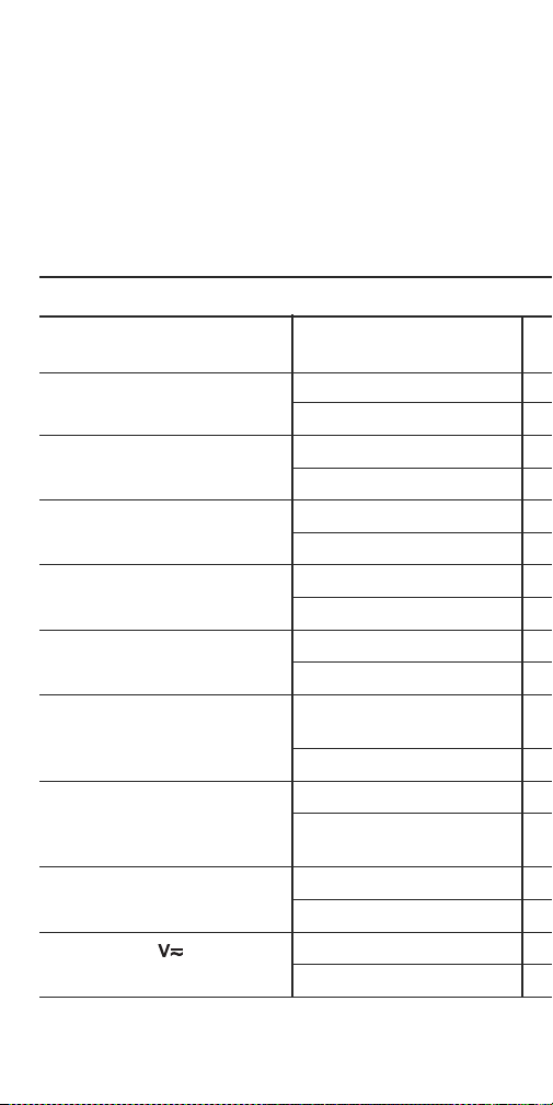
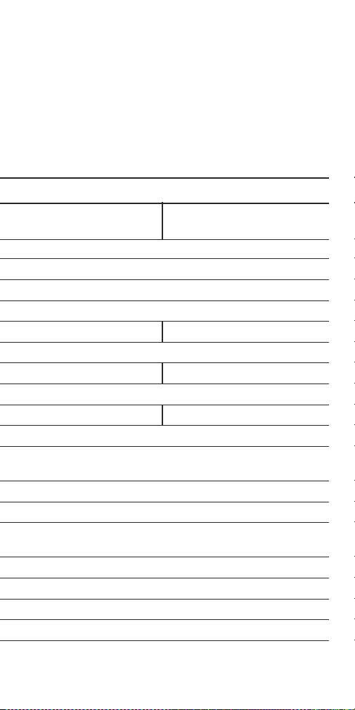
SPECIFICATIONS
Parameter or
Feature/Function Specification
AC voltage (True
DC voltage Measurement ranges
AC current (True
Inrush current (True
DC current Measurement ranges
AC/DC microamp current
(True
RMS
)
Resistance Measurement ranges
) Measurement ranges
RMS
Measurement accuracy
Measurement accuracy
) Measurement ranges
RMS
Measurement accuracy
) Measurement ranges
RMS
Measurement accuracy
Measurement accuracy
Measurement ranges
Measurement accuracy
Measurement accuracy
Frequency (through clamp jaw) Measurement ranges
Measurement accuracy
Frequency (in mode) Measurement ranges
Measurement accuracy
24
Page 26
(4) To measure a surface temperature, firmly attach
the tip or bead of the thermocouple to the surface.
To measure the temperature of a liquid or gas
(including ambient air), make sure that the tip of
the thermocouple is within the fluid.
Read the measured temperature on the primary
readout in degrees Fahrenheit and on the secondary
readout in degrees Celsius.
((M66((M70
25
±(1.2% of reading + 3 digits)@≥1MΩ
RMS
RMS
Page 27
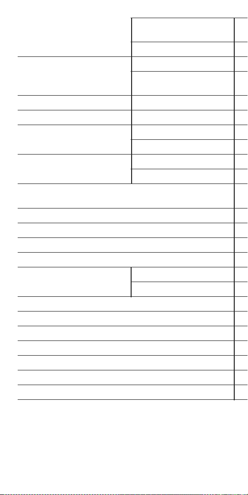
Frequency (in Hz mode) Measurement ranges
Measurement accuracy
Capacitance Measurement ranges
Measurement accuracy
Continuity Threshold
Diode integrity Open circuit voltage
Duty cycle Measurement range
Measurement accuracy
Temperature (via included
“K” type stem thermocouple)
Measurement range
Measurement accuracy
Overload protection level in resistance, continuity,
diode integrity, capacitance and 애A modes
Input impedance
Sampling time
Safety rating
Clamp jaw opening
Display No. of digits
Maximum count
Auto power off trigger
Operating temperature
Storage temperature
Maximum altitude
Power source
Dimensions
Weight (including batteries)
Note:
Accuracy values are guaranteed for 1 year after factory
calibration at an operating temperature between 64° and 82°F
(18° and 28°C). All accuracy specifications must be derated
(increased) by 5.5% for each degree F of operating temperature
outside this range.
For example, an accuracy specification of ±3% between 64°F and
82°F would be derated to:
26
Page 28

3V peak-to-peak square wave
±(4% of reading+ 5 digits)@>10nF
≤ 50Ω
250VAC/DC
8.86 x 3.31 x 1.30 in. (225 x 84 x 33mm)
•
±3.165%
83°F
•
±3.33%
84°F
•
±3.495%
85°F
(±3% + (3% x 5.5% x 1))
(one degree outside the range)
(±3% + (3% x 5.5% x 2)) f
(two degrees outside the range)
(±3% + (3% x 5.5% x 3))
(three degrees outside the range) · etc.
RMS
for operation at 63°F and
or operation at 62°F and
for operation at 61°F and
27
Page 29

OPERATING &
MAINTENANCE TIPS
When the icon appears at the upper left of the
LCD, it’s time to replace the three “AAA” batteries that
power the meter (although measurements will remain
valid for several hours after the icon first appears). To
replace the battery, follow the instructions on p. 10.
Do not operate the HHM660/701 in the presence of
flammable or explosive gas or near an arc welder or
induction heater.
After subjecting the meter to a large change in
ambient temperature, wait at least 30 minutes before
making measurements to guarantee the accuracy of
readings.
Remove the batteries when storing the meter or when
you do not expect to use it for an extended period of
time (months rather than weeks).
Do not disassemble the HHM660/701 or immerse it in
water.
28
Page 30

NOTES
______________________________________
______________________________________
______________________________________
______________________________________
______________________________________
______________________________________
______________________________________
______________________________________
______________________________________
______________________________________
______________________________________
______________________________________
______________________________________
______________________________________
______________________________________
______________________________________
______________________________________
______________________________________
______________________________________
______________________________________
_____________________________________
Page 31

OMEGA ENGINEERING, INC. warrants this unit to be free of defects in materials
and workman-ship for a period of 13 months from date of purchase. OMEGA’s
Warranty adds an additional one (1) month grace period to the normal one (1)
year product warranty to cover handling and shipping time. This ensures that
OMEGA’s customers receive maximum coverage on each product.
If the unit malfunctions, it must be returned to the factory for evaluation.
OMEGA’s Customer Service Department will issue an Authorized Return (AR)
number immediately upon phone or written request. Upon examination by
OMEGA, if the unit is found to be defective, it will be repaired or replaced at
no charge. OMEGA’s WARRANTY does not apply to defects resulting from
any action of the purchaser, including but not limited to mishandling, improper
interfac-ing, operation outside of design limits, improper repair, or
unauthorized modification. This WARRANTY is VOID if the unit shows evidence
of having been tampered with or shows evidence of having been damaged as a
result of excessive corrosion; or current, heat, moisture or vibra-tion; improper
specification; misapplication; misuse or other operating conditions outside of
OMEGA’s control. Components in which wear is not warranted, include but are
not limited to contact points, fuses, and triacs.
OMEGA is pleased to offer suggestions on the use of its various
products. However, OMEGA neither assumes responsibility for any
omissions or errors nor assumes liability for any damages that result
from the use of its products in accordance with information provided
by OMEGA, either verbal or written. OMEGA warrants only that the
parts manufactured by the company will be as specified and free of
defects. OMEGA MAKES NO OTHER WARRANTIES OR
REPRESENTATIONS OF ANY KIND WHATSOEVER, EXPRESSED OR
IMPLIED, EXCEPT THAT OF TITLE, AND ALL IMPLIED WARRANTIES
INCLUDING ANY WARRANTY OF MERCHANTABILITY AND FITNESS
FOR A PARTICULAR PURPOSE ARE HEREBY DISCLAIMED. LIMITATION
OF LIABILITY: The remedies of purchaser set forth herein are
exclusive, and the total liability of OMEGA with respect to this order,
whether based on contract, warranty, negligence, indemnification,
strict liability or otherwise, shall not exceed the purchase price of
the component upon which liability is based. In no event shall OMEGA
be liable for consequential, incidental or special damages.
CONDITIONS: Equipment sold by OMEGA is not intended to be used, nor shall it
be used: (1) as a “Basic Component” under 10 CFR 21 (NRC), used in or with any
nuclear installation or activity; or (2) in medical applications or used on humans.
Should any Product(s) be used in or with any nuclear installation or activity,
medical application, used on humans, or misused in any way, OMEGA
assumes no responsibility as set forth in our basic WARRANTY/ DISCLAIMER
language, and, additionally, purchaser will indemnify OMEGA and hold OMEGA
harmless from any liability or damage whatsoever arising out of the use of the
Product(s) in such a manner.
Direct all warranty and repair requests/inquiries to the OMEGA
Customer Service Department. BEFORE RETURNING ANY
PRODUCT(S) TO OMEGA, PURCHASER MUST OBTAIN AN
AUTHORIZED RETURN (AR) NUMBER FROM OMEGA’S CUSTOMER
SERVICE DEPARTMENT (IN ORDER TO AVOID PROCESSING DELAYS).
The assigned AR number should then be marked on the outside of the
return package and on any correspondence. The purchaser is responsible
for shipping charges, freight, insurance and proper packaging to prevent
breakage in transit.
FOR WARRANTY RETURNS,
please have the following
information available BEFORE
contacting OMEGA:
Purchase Order number under
1.
which the product was
PURCHASED,
Model and serial number of the
2.
product under warranty, and
Repair instructions and/or
3.
specific problems relative
to the product.
OMEGA’s policy is to make running changes, not model changes,
whenever an improvement is possible. This affords our customers
the latest in technology and engineering.
OMEGA is a registered trademark of OMEGA ENGINEERING, INC.
© Copyright 2015 OMEGA ENGINEERING, INC. All rights reserved. This
document may not be copied, photocopied, reproduced, translated, or
reduced to any electronic medium or machine-readable form, in whole or in
part, without the prior written consent of OMEGA ENGINEERING, INC.
WARRANTY/ DISCLAIMER
RETURN REQUESTS/ INQUIRIES
FOR NON-WARRANTY REPAIRS,
consult OMEGA for current repair
charges. Have the following
information available BEFORE
contacting OMEGA:
Purchase Order number to
1.
cover the COST of the repair,
Model and serial number of
2.
the product, and
Repair instructions and/or
3.
specific problems relative
to the product.
Page 32

Where Do I Find Everything I Need for
Process Measurement and Control?
OMEGA…Of Course!
Shop online at omega.com
SM
TEMPERATURE
MU
Thermocouple, RTD & Thermistor
Probes, Connectors, Panels &
Assemblies
MU
Wire: Thermocouple, RTD &
Thermistor
MU
Calibrators & Ice Point References
MU
Recorders, Controllers & Process
Monitors
MU
Infrared Pyrometers
PRESSURE, STRAIN AND
FORCE
MU
Transducers & Strain Gages
MU
Load Cells & Pressure Gages
MU
Displacement Transducers
MU
Instrumentation & Accessories
FLOW/LEVEL
MU
Rotameters, Gas Mass Flowmeters
& Flow Computers
MU
Air Velocity Indicators
MU
Turbine/Paddlewheel Systems
MU
Totalizers & Batch Controllers
pH/CONDUCTIVITY
MU
pH Electrodes, Testers &
Accessories
MU
Benchtop/Laboratory Meters
MU
Controllers, Calibrators, Simulators
& Pumps
MU
Industrial pH & Conductivity
Equipment
DATA ACQUISITION
MU
Data Acquisition & Engineering
Software
MU
Communications-Based Acquisition
Systems
MU
Plug-in Cards for Apple, IBM &
Compatibles
MU
Data Logging Systems
MU
Recorders, Printers & Plotters
HEATERS
MU
Heating Cable
MU
Cartridge & Strip Heaters
MU
Immersion & Band Heaters
MU
Flexible Heaters
MU
Laboratory Heaters
ENVIRONMENTAL
MONITORING AND CONTROL
MU
Metering & Control
Instrumentation
MU
Refractometers
MU
Pumps & Tubing
MU
Air, Soil & Water Monitors
MU
Industrial Water & Wastewater
Treatment
MU
pH, Conductivity & Dissolved
Oxygen Instruments
M5560/0716
 Loading...