

Page 1

User’s Guide
Shop online at
omega.com
e-mail: [email protected]
For latest product manuals:
www.omegamanual.info
SM
HHLT-2
Refrigerant Leak Detector
With Pump
Page 2

omega.com [email protected]
Servicing North America:
U.S.A.: Omega Engineering, Inc., One Omega Drive, P.O. Box 4047
Stamford, CT 06907-0047 USA
Toll-Free: 1-800-826-6342 (USA & Canada only)
Customer Service: 1-800-622-2378 (USA & Canada only)
Engineering Service: 1-800-872-9436 (USA & Canada only)
Tel: (203) 359-1660 Fax: (203) 359-7700
e-mail: [email protected]
For Other Locations Visit omega.com/worldwide
The information contained in this document is believed to be correct, but OMEGA accepts no liability for any errors it
contains, and reserves the right to alter specifications without notice.
Page 3

TABLE OF CONTENTS
Introduction . . . . . . . . . . . . . . . . . . . . . . . . . . . . . . . . . . . . . . . . . . . . . 2 –4
How It Works . . . . . . . . . . . . . . . . . . . . . . . . . . . . . . . . . . . . . . . . 3 –4
Key Features. . . . . . . . . . . . . . . . . . . . . . . . . . . . . . . . . . . . . . . . . . . . . . . . 4
What’s in the Case . . . . . . . . . . . . . . . . . . . . . . . . . . . . . . . . . . . . . . . . . . . 5
Setup Instructions. . . . . . . . . . . . . . . . . . . . . . . . . . . . . . . . . . . . . . . . . . . . 5
Install Batteries . . . . . . . . . . . . . . . . . . . . . . . . . . . . . . . . . . . . . . . . . 5
Operating Instructions . . . . . . . . . . . . . . . . . . . . . . . . . . . . . . . . . . . . . 5 –8
Starting Up . . . . . . . . . . . . . . . . . . . . . . . . . . . . . . . . . . . . . . . . . 5 –6
Checking for Leaks . . . . . . . . . . . . . . . . . . . . . . . . . . . . . . . . . . . 6 –7
Using the Leak Test Vial. . . . . . . . . . . . . . . . . . . . . . . . . . . . . . . . . . . 8
Specifications . . . . . . . . . . . . . . . . . . . . . . . . . . . . . . . . . . . . . . . . . . . . . . . 9
Maintenance Instructions . . . . . . . . . . . . . . . . . . . . . . . . . . . . . . . . . . . . . . 9
Changing the Batteries . . . . . . . . . . . . . . . . . . . . . . . . . . . . . . . . . . . 9
Replacing the Filter . . . . . . . . . . . . . . . . . . . . . . . . . . . . . . . . . . . . . . 9
Warranty Information . . . . . . . . . . . . . . . . . . . . . . . . . . . . . . . . . . . . . . . . 10
Return for Repair Policy . . . . . . . . . . . . . . . . . . . . . . . . . . . . . . . . . . . . . . 10
INTRODUCTION
Thank you for purchasing OMEGA’s HHLT-2 Digital Refrigerant Leak Detector with
Pump. Please read this user’s manual carefully and thoroughly before using the
product.
The HHLT-2’s long-lasting solid electrolyte semiconductor sensor can detect leaks of all
hal
ogenated (chlorine or fluorine-based) refrigerant gases currently in common use.
They include HFCs (hydrofluorocarbons), CFCs (chlorofluorocarbons) and HCFCs
(hydrochlorofluorocarbons).
Specifically, the instrument can detect:
• Widely used HFC refrigerants such as R-134a, R-410a, R-404a, R-407c and R-507
• CFC refrigerants such as CFC-12 (R-12)—commonly known as Freon
• HCFC replacement blends, such as R-22, approved by the U.S. EPA for complying with
the stratospheric ozone protection provisions of the Clean Air Act
• R-1234yf, the newly approved hydrofluoroolefin (HFO) refrigerant with a global
warming potential 335 times less than that of R-134a
Electronic sensing is the most widely used, sensitive and accurate method of refrigerant
leak detection.
2
Page 4

WHY LOOK FOR REFRIGERANT LEAKS?
There are three reasons to detect and repair leaks of refrigerant gases from
stationary and mobile air conditioners, refrigeration systems and heat pumps:
1. Leaks allow air and moisture to enter an A/C system or chiller. Moisture can
react with refrigerant to form corrosive acids and sludge that can damage a
compressor, plug up orifice tubes, and/or eat pinholes in evaporators and
condensers.
2. Refrigerant is expensive. It may seem cheaper to keep recharging your
system with refrigerant than fix a leak—but it isn’t in the long run. And A/C
systems and chillers that aren’t fully charged won’t cool efficiently and thus
waste money (electricity-powered systems) or fuel (vehicle systems).
3. Most refrigerants deplete the ozone layer that blocks the Sun's harmful
ultraviolet radiation. In the U.S., the Clean Air Act of 1990 and later
amendments require owners or operators of refrigeration and airconditioning equipment with refrigerant charges greater than 50 pounds to
repair leaks within 30 days when those leaks resul
t in the loss of more than
15% (comfort cooling) or 35% (commercial cooling) of the charge over a
12-month period.
The HHLT-2’s proprietary sensor and detection technology are the keys to its excellent
performance and durability. Compared to products of decades past with “heated
sensors”, the HHLT-2 warms its sensor to a much lower temperature. The reduction in
heat reduces the instrument’s power consumption and improves sensor stability while
extending the life of the sensor and maintaining its electrochemical function.
Test data indicate no decline in the sensor’s performance after thousands of hours of
operation. Sensor life is specified at more than ten years of normal use. In addition,
because the instrument and sensor comply with SAE Standards J2791 and J2913 and
the European Standard EN14624, the sensor will not be damaged by overexposure to
refrigerant gas or by contamination by water. To comply with SAE J2791, the HHLT-2
also had to demonstrate its sensitivity to 15 different chemicals and pass two “garage
durability” tests, one requiring it to survive three drops from 4 ft. onto concrete.
HOW IT WORKS
A small mecha
nical pump inside the HHLT-2 draws a sample of air through the tip of
the instrument’s 17-in. long probe into a proprietary sensor 1-1/2 inches downstream. A
proportional halogen detector in the sensor determines whether any refrigerant gas is in
the sample. If any gas is detected, the sensor and other circuits measure the amount of
refrigerant and convert the value to an electrical signal.
If no leak is detected, no signal is produced and the display remains off (dark). When a
leak is detected, the signal is amplified, digitized, and displayed on the front panel as a
large, bright red number from 1 to 9 corresponding to the size of the leak (1 for the
smallest leaks, 9 for the largest).
3
Page 5

The digital readout makes it easy to pinpoint the source of a leak and helps you decide
whether it is large enough to be worth plugging. The reading is independent of the
selected sensitivity level (three are available) and is at its highest when the tip of the
probe is at the source of the leak. A table in the Operating Instructions section of this
manual correlates display readings with leak size, in ounces per year.
The HHLT-2 simultaneously uses sound to help locate the source of a leak. Whenever
the unit is on, it continuously produces three very loud beeps every two seconds. When
a leak is detected, the frequency of the beeping increases dramatically. The beeper can
be muted by pressing a dedicated button on the front panel.
A third feature of the HHLT-2 that helps locate leaks is a red LED adjacent to the sensor
at the end of the probe. This light flashes in sync with the beep. In other words, it flashes
three times every two seconds whenever the unit is on, and much faster whenever the
unit detects refrigerant. When the red LED begins to flash rapidly, your eye will naturally
be drawn to it—and therefore the location of the leak. Like the leak-size readout, the
LED at the end of the probe is bright enough to be visible in full sunlight.
The HHLT-2 automatically compensates for ambient levels of refrigerant gas. No
manual sensitivity adjustments or power adjustments are required.
The instrument is supplied with a proprietary leak test vial that lets you verify that it is
working properly prior to searching for a leak. The HHLT-2 is powered by four “AA”
ca
batteries, which are included in the
se.
KEY FEATURES
• Proprietary sensor with lifetime of thousands of hours of operation (ten years of
normal use)
• Detects all commercially available HFC, HFO, HC, HCFC and CFC refrigerants as well
as blends and newly approved replacements such as R-22 and R-1234yf
• Triple-redundant leak indication (loud fast beep, bright flashing LED, digital leak size
reading)
• True mechanical pump draws in samples, increasing sensitivity
• Sensitivity of 0.05 oz./year (1.4 g/year) to R-134a
• Three sensitivity levels
• Fast warmup • Comfortable neoprene grip
• Automatic calibration and reset to ambient levels • Mutable beeper
• Garage-durable construction • Leak test vial
• Low battery indicator • Padded hard plastic case
• Made in U.S.A. • SAE J2791 and J2913 certified
• 2-year warranty includes sensor • CE, RoHS, WEEE approved
• Complies with European standard EN 14624
4
Page 6
WHAT’S IN THE CASE
The HHLT-2 comes fully assembled in a padded hard plastic carrying case. Also in the
case are a leak test vial (for checking that the unit is performing properly), a pack of four
“AA” batteries, five spare sensor filters and this user’s manual.
SETUP INSTRUCTIONS
INSTALL BATTERIES
To install the four included “AA” batteries,
use a Phillips-head screwdriver to open
Polarity Marks
the hinged door of the two-sided battery
compartment at the bottom of the
HHLT-2. Insert two batteries in the right
side of the compartment (+) end first,
and the other two in the left compartment (-) end first. To help you do this correctly,
th
ere are (+) and (-) polarity marks on the hinged door (see figure at right). Be sure each
mark ends up next to the corresponding terminal of a battery.
OPERATING INSTRUCTIONS
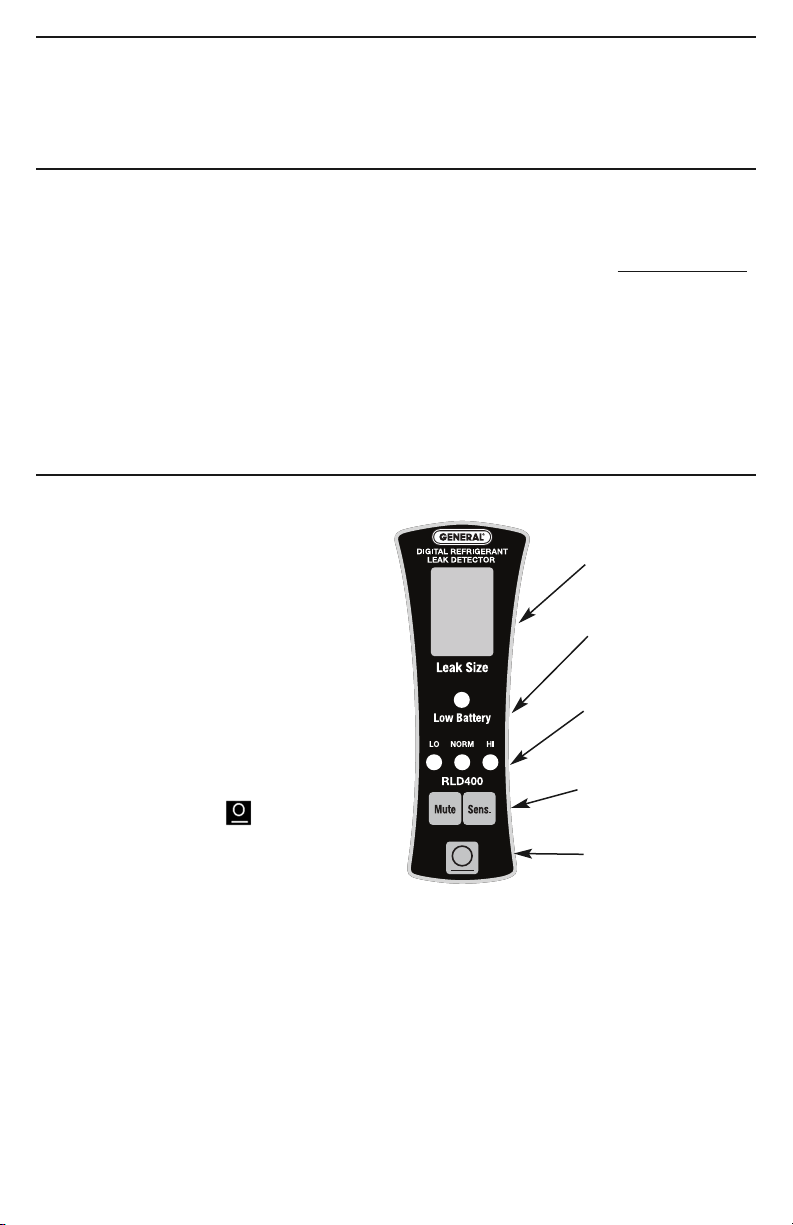
All of the HHLT-2’s controls and
indicators are on the front panel.
Familiarize yourself with the names and
positions of the controls and indicators
shown below before moving on to the
Setup Instructions and Operating
Instructions.
STARTING UP
Before the HHLT-2 can be used to detect
refrigerant leaks, it must execute the
following three-step startup sequence:
1) TURN ON. Press the button to
power on the unit.
2)
WARM UP. Once the unit has been
powered on, it will automatically begin
heating the sensor. During warmup, 1) the digital leak size indicator flashes “0”;
2)
the yellow, red and green sensitivity LEDs illuminate in sequence; and 3) the
beeper sounds repeatedly at a rate of three beeps every two seconds. To silence the
beep, press the Mute button. The warmup cycle normally takes 17–20 seconds.
3)
READY. The HHLT-2 is ready to search for leaks when: 1) the display stops flashing
“0” and goes dark; 2) the green LED indicating NORM sensitivity (the default level)
lights up; and 3) you hear and feel the internal pump start up.
Digital leak size
indicator
Low battery indicator
(red LED)
Sensitivity level LEDs
(yellow, green, red)
Beeper mute and
sensitivity buttons
Power on/off button
5
Page 7

IMPORTANT: The startup sequence will not execute to completion if the refrigerant gas
sensor cannot be heated. That would be the case if the sensor becomes electrically
disconnected from the probe.
The sensor (which is under the black probe tip assembly) is physically and electrically
connected to the probe by a six-pin socket visible under the clear plastic near the red
“refrigerant detected” LED near the end of the probe (see figure below).
If the startup sequence fails to complete after 60 seconds, abort the process by
powering off the unit. Then check the integrity of the connection between the sensor and
the probe by doing the following:
1) Pull the black probe tip assembly straight out and away from the sensor socket
without twisting it. This disconnects the sensor.
2) Line up the keyway notch on the probe tip assembly with the raised keyway on the
sensor socket holder
3) Carefully push the sensor back into the socket without forcing or twisting it;
misalignment can damage the sensor’s pins. This reconnects the sensor.
Sensor socket and
red “refrigerant
detected” LED
CHECKING FOR LEAKS
Position the end of the HHLT-2’s flexible-obedient probe—which retains its configured
shape—close to any suspected
source of leaking refrigerant gas. In a vehicle, wet oily
areas around hose connections and fittings, and greasy streaks radiating outward
around the compressor clutch or on the underside of the hood just above the
compressor are telltale signs of a leak. Another place to check sooner rather than later
is the evaporator (located inside the heater/defroster plenum under the dash).
Whenever the sensor at the end of the probe senses a refrigerant gas that it has been
designed to detect:
1) The red LED at the end of the probe will begin flashing much faster than three times
every two seconds
2) The beeper will increase its own frequency correspondingly
3) A number from 1 to 9 will appear in the digital leak size indicator window.
6
Page 8

The reading reflects the concentration of refrigerant gas sensed. The maximum value
will be displayed when the tip of the probe is at the source of the leak. Try switching
between different sensitivity levels while moving the probe until the highest number
appears.
To raise the sensitivity level, press the SENS. button once; this will light the red LED
labeled HI. To lower the sensitivity level, press the SENS. button again; this will light the
yellow LED labeled LO.
The table below can be used to approximate the size of a leak.
Maximum Value Leak Size (oz./yr)
Displayed
1 to 3 < 0.1
4 to 6 0.1 to 0.5
7 to 9 >0.5
Note re: Cross sensitivity to automotive chemicals
Some automotive solvents and chemicals have hydrocarbon properties similar to R134a
and therefore may produce a non-zero reading on the digital leak detector. Before
checking for refrigerant leaks, clean up any chemicals in the list below, which may
produce a positive response.
Brand/type Response
Rain-X windshield washer fluid Y
Ford spot remover (wet) Y
Ford rust inhibitor Y
Ford gasket adhesive (wet) Y
Loctite Natural Blue degreaser (diluted) Y
Ford brake parts cleaner Y
Ford silicone rubber (uncured) Y
Motorcraft antifreeze heated to 160°F Y
Gunk liquid wrench Y
Ford pumice lotion (with solvent) Y
Ford Motorcraft brake fluid Y
Ford carburetor cleaner Y
7
Page 9

USING THE LEAK TEST VIAL
The HHLT-2 ships with a leak test vial that lets you check whether the instrument is
working properly. To perform this check:
1) Remove the leak test vial from its Ziploc plastic bag and remove the black rubber cap
from the top of the vial. The cap pops off, rather than unscrews (see figure below).
The first time you use the vial, you must remove and discard the circular insert under
the black plastic screw-on cap with pinhole.
Power on the HHLT-2 and wait for it to complete the
2)
three-step startup sequence.
3) Position the tip of the probe at the pinhole in the top of
the vial’s screw-on cap. If the HHLT-2 is working
properly, the beep rate and the flashing frequency of the
red LED near the probe tip will increase dramatically. A
number between
4 and 6 should
appear on the digital leak size indicator if you are using
the vial included with the unit.
4) Put the black rubber cap back over the vial’s screw-on cap.
Black rubber
cap (remove
to test)
Black plastic
screw-on cap
with pinhole
(DO NOT
remove to test)
Glass leak
test vial
If you do not, the contents of the vial will evaporate over time.
NOTE: If the above check does not produce a non-zero reading, either your leak test vial
is empty or your HHLT-2 is defective. If the bottom of your leak test vial does not appear
green, replace the vial. To locate a replacement, search the Internet for “Refrigerant leak
detector reference”.
If a full leak test vial does not produce a non-zero reading, it is likely that your HHLT-2
is defective (or requires a new sensor). General will repair or replace your unit (or its
sensor) if you purchased it within the past two years and have complied with the terms
of the HHLT-2’s limited warranty. Contact our Customer Service department at
800-872-9436 to obtain a Return Goods Authorization (RGA) number before shipping
the unit.
8
Page 10

SPECIFICATIONS
Refrigerants Detected R-134a, R-410a, R-404a, R-407c, R-507, CFC-12
(R-12 or Freon), R-22, R-1234yf
Detection Modalities Sound, light, leak size measure
Sensitivities 0.05 oz./yr (1.4 g/yr) for R-134a; 0.025 oz./yr (0.7g/yr)
for R-22
Sensor Type Proprietary solid electrolyte semiconductor
Sensor Life >300 hours (ten years’ normal use)
Warmup Time 17–20 seconds
Response Time Instantaneous
Display Type, Size 7-segment red LED, 0.6 in. (15mm) high
Dimensions of Instrument
Weight of Instrument 1.5 lb. (680g)
Dimensions of Carrying Case 15 x 11 x 4 in. (382 x 279 x 102mm)
Weight of Instrument, 2 lbs, 5.5 oz. (1.06kg)
Batteries and Carrying Case
Complies with SAE Standards J2791 and J2913,
Limited Warranty Term 2 years (including sensor)
Power Source 4 “AA” batteries (included)
Battery Life 5 hours continuous operation (typical)
6.8 x 2.6 x 2.2 in. (173 x 66 x 56mm) w/17 in. (432mm) probe
European Standard EN14624
MAINTENANCE INSTRUCTIONS
CHANGING BATTERIES
When the red front-panel LED labeled Low Battery lights up, it’s time to replace the
instrument’s four “AA” batteries. To do so, follow the procedure in the Setup Instructions
section of this manual.
CHANGING THE FILTER
The HHLT-2 ships with a pack of five small disc filters that install upstream of the
sensor. Replace the filter whenever it becomes visibly dirty, or every few months,
depending on use.
To change the filter, unscrew the black plastic tip of the probe from the black plastic
sensor enclosure (see figure on p. 6.) Remove the old filter, install the new one, and then
screw the plastic tip back into the enclosure.
9
Page 11

NOTES
________________________________________________________________
________________________________________________________________
________________________________________________________________
________________________________________________________________
________________________________________________________________
________________________________________________________________
________________________________________________________________
________________________________________________________________
________________________________________________________________
________________________________________________________________
________________________________________________________________
________________________________________________________________
________________________________________________________________
________________________________________________________________
________________________________________________________________
________________________________________________________________
________________________________________________________________
________________________________________________________________
________________________________________________________________
________________________________________________________________
________________________________________________________________
________________________________________________________________
________________________________________________________________
________________________________________________________________
10
Page 12

WARRANTY/DISCLAIMER
OMEGA ENGI NEERING, INC. warrants this unit to be free of defects in materials and
workmanship for a period of 13 months from date of purchase. OMEGA’s WARRANTY adds
an additional one (1) month grace period to the normal one (1) year product warranty to
cover handling and shipping time. This ensures that OMEGA’s customers receive maximum
coverage on each product.
If the unit malfunctions, it must be returned to the factory for evaluation. OMEGA’s Customer
Service Department will issue an Authorized Return (AR) number immediately upon phone
or written request. Upon examination by OMEGA, if the unit is found to be defective, it
will be repaired or replaced at no charge. OMEGA’s WARRANTY does not apply to defects
resulting from any action of the purchaser, including but not limited to mishandling, improper
interfacing, operation outside of design limits, improper repair, or unauthorized modification.
This WARRANTY is VOID if the unit shows evidence of having been tampered with or shows
evidence of having been damaged
or vibration; improper specification; misapplication; misuse or other operating conditions
outside of OMEGA’s control. Components in which wear is not warranted, include but are not
limited to contact points, fuses, and triacs.
OMEGA is pleased to offer suggestions on the use of its various products. However,
OMEGA neither assumes responsibility for any omissions or errors nor assumes
liability for any damages that result from the use of its products in accordance
with information provided by OMEGA, either verbal or written. OMEGA warrants
only that the parts manufactured by the company will be as specified and free of
defects. OMEGA MAKES NO OTHER WARRANTIES OR REPRESENTATIONS OF ANY
KIND WHATSOEVER, EXPRESSED OR IMPLIED, EXCEPT THAT OF TITLE, AND ALL
IMPLIED WARRANTIES INCLUDING ANY WARRANTY OF MERCHANTABILITY AND
FITNESS FOR A PARTICULAR PURPOSE ARE HEREBY DISCLAIMED. LIMITATION
OF LIABILIT
Y: The remedies of purchaser set forth herein are exclusive, and the
total liability of OMEGA with respect to this order, whether based on contract,
warranty, negligence, indemnification, strict liability or otherwise, shall not exceed
the purchase price of the component upon which liability is based. In no event shall
OMEGA be liable for consequential, incidental or special damages.
CONDITIONS: Equipment sold by OMEGA is not intended to be used, nor shall it be used: (1)
as a “Basic Component” under 10 CFR 21 (NRC), used in or with any nuclear installation or
activity; or (2) in medical applications or used on humans. Should any Product(s) be used in or
with any nuclear installation or activity, medical application, used on humans, or misused in
any way, OMEGA assumes no responsibility as set forth in our basic WARRANTY / DISCLAIMER
language, and, additionally, purchaser will indemnify OMEGA and hold OMEGA harmless from
any liability or damage whatsoever arising out of the use of the Product(s) in such a manner.
as a result of excessive corrosion; or current, heat, moisture
Direct all warranty and repair requests/inquiries to the OMEGA Customer Service Department.
RETURN REQUESTS/INQUIRIES
BEFORE RETURNING ANY PRODU CT(S) TO OMEGA, PURCHASER MUST OBTAIN AN
AUTHORIZED RETURN (AR) NUMBER FROM OMEGA’S CUSTOMER SERVICE DEPARTMENT
(IN ORDER TO
marked on the outside of the return package and on any correspondence.
The purchaser is responsible for shipping charges, freight, insurance and proper packaging to
prevent breakage in transit.
FOR WARRANTY RETURNS, please have
the following information available BEFORE
contacting OMEGA:
1. Purchase Order number under which
the product was PURCHASED,
2. Model and serial number of the product
under warranty, and
3. Repair instructions and/or specific
problems relative to the product.
OMEGA’s policy is to make running changes, not model changes, whenever an improvement is possible.
This affords our customers the latest in technology and engineering.
OMEGA is a registered trademark of OMEGA ENGINEERING, INC.
© Copyright 2015 OMEGA ENGINEERING, INC. All rights reserved. This document may not be copied, photocopied,
reproduced, translated, or reduced to any electronic medium or machine-readable form, in whole or in part, without
the prior written consent of OMEGA ENGINEERING, INC.
AVOID PROCESSING DELAYS). The assigned AR number should then be
FOR NON-WARRANTY REPAIRS,
consult
OMEGA for current repair charges. Have the
following information available BEFORE
contacting OMEGA:
1. Purchase Order number to cover the
COST of the repair,
2. Model and serial number of the product, and
3. Repair instructions and/or specific problems
relative to the product.
Page 13

Where Do I Find Everything I Need for
Process Measurement and Control?
OMEGA…Of Course!
Shop online at omega.com
TEMPERATURE
MU
Thermocouple, RTD & Thermistor Probes, Connectors, Panels & Assemblies
MU
Wire: Thermocouple, RTD & Thermistor
MU
Calibrators & Ice Point References
MU
Recorders, Controllers & Process Monitors
MU
Infrared Pyrometers
PRESSURE, STRAIN AND FORCE
MU
Transducers & Strain Gages
MU
Load Cells & Pressure Gages
MU
Displacement Transducers
MU
Instrumentation & Accessories
FLOW/LEVEL
MU
Rotameters, Gas Mass Flowmeters & Flow Computers
MU
Air Velocity Indicators
MU
Turbine/Paddlewheel Systems
MU
Totalizers & Batch Controllers
pH/CONDUCTIVITY
MU
pH Electrodes, Testers & Accessories
MU
Benchtop/Laboratory Meters
MU
Controllers, Calibrators, Simulators & Pumps
MU
Industrial pH & Conductivity Equipment
SM
DATA ACQUISITION
MU
Data Acquisition & Engineering Software
MU
Communications-Based Acquisition Systems
MU
Plug-in Cards for Apple, IBM & Compatibles
MU
Data Logging Systems
MU
Recorders, Printers & Plotters
HEATERS
MU
Heating Cable
MU
Cartridge & Strip Heaters
MU
Immersion & Band Heaters
MU
Flexible Heaters
MU
Laboratory Heaters
ENVIRONMENTAL
MONITORING AND CONTROL
MU
Metering & Control Instrumentation
MU
Refractometers
MU
Pumps & Tubing
MU
Air, Soil & Water Monitors
MU
Industrial Water & Wastewater Treatment
MU
pH, Conductivity & Dissolved Oxygen Instruments
M5454/0315
 Loading...