

Page 1
User’s Guide
Shop online at
omega.com
e-mail: [email protected]
For latest product manuals:
www.omegamanual.info
SM
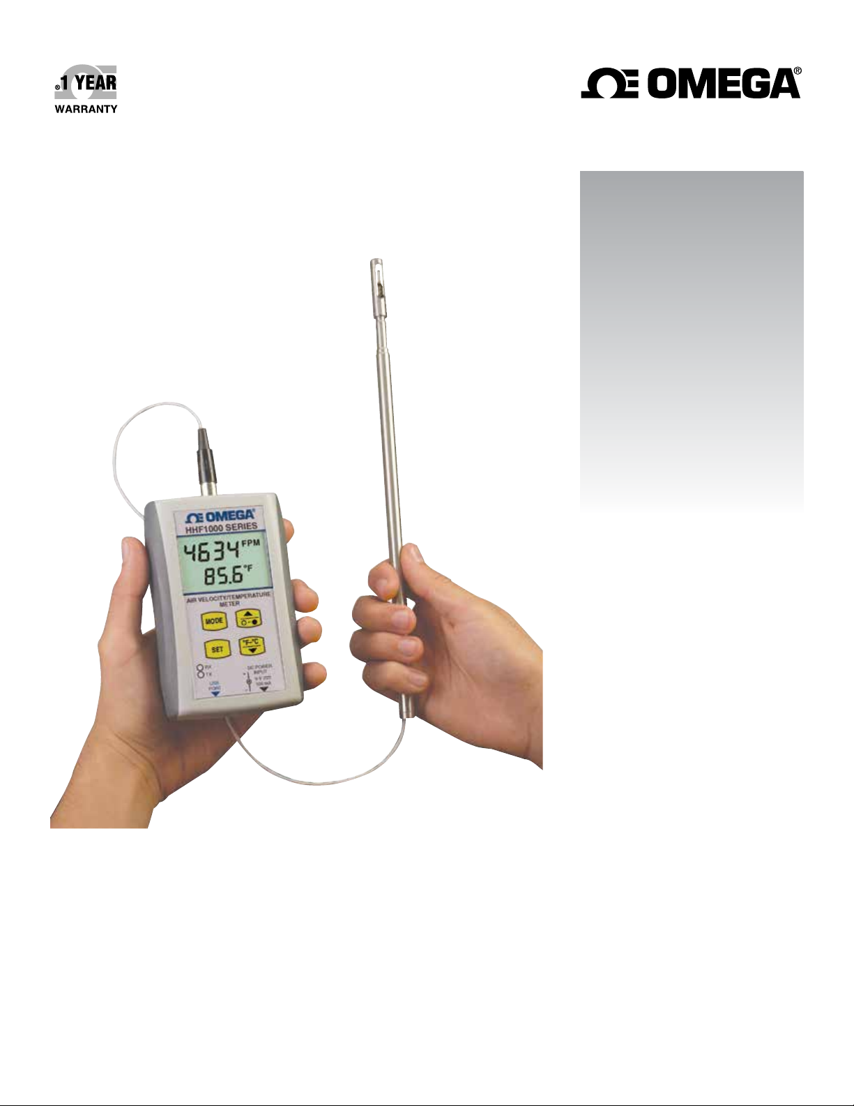
HHF1000 SERIES
Handheld Air Velocity/
Temperature Meter with Wireless
PC Communication Option
Page 2

omega.com [email protected]
Servicing North America:
U.S.A. Omega Engineering, Inc.
Headquarters: Toll-Free: 1-800-826-6342 (USA & Canada only)
Customer Service: 1-800-622-2378 (USA & Canada only)
Engineering Service: 1-800-872-9436 (USA & Canada only)
Tel: (203) 359-1660 Fax: (203) 359-7700
e-mail: [email protected]
For Other Locations Visit omega.com/worldwide
The information contained in this document is believed to be correct, but OMEGA accepts no liability for any errors it contains, and reserves
the right to alter specifications without notice.
Page 3

Table of Contents
Section Page
Section 1 - Package Introduction ...................................................................... 1-1
Section 2 - Installation ........................................................................................ 2-1
Section 3 - Main Operation ................................................................................ 3-1
Section 4 - PC Interface ....................................................................................... 4-1
Section 5 - Wireless PC Communications ....................................................... 5-1
Section 6 - Specifications .................................................................................... 6-1
Section 7 - Approvals, Regulatory Compliance ............................................. 7-1
HHF1000 SERIES
Handheld Air Velocity/Temperature Meter
i
Page 4

HHF1000 SERIES
Handheld Air Velocity/Temperature Meter
List of Figures and Tables
Figure Description Page
Table 1 Piping Requirement ........................................................................... 2-2
2-1 HHF1000 General Dimensions And Controls ............................... 2-3
2-2 HHF1000 Fixed Probe Mount and Remote Telescopic Probe ..... 2-4
Table 2 Keypad Functional Flow Chart ........................................................ 3-2
3-1 Display Functional Flow Chart ........................................................ 3-3
4-1 Main Window ..................................................................................... 4-2
4-2 Typical Data File ................................................................................ 4-2
4-3 Settings Menu ..................................................................................... 4-3
5-1 UWTC-REC1 Wireless Receiver ...................................................... 5-1
5-2 General and Mounting Dimensions ................................................ 5-2
5-3 FCC Warning Label ........................................................................... 5-2
5-4 Establishing Communications With HHF1000 Screen ................. 5-3
5-5 Options Menu Screen ........................................................................ 5-4
5-6 TC Central Main Menu Screen ......................................................... 5-5
5-7 Y Axis Configuration Screen ............................................................ 5-6
5-8 Data Plotting/Logging Menu Selection Screen ............................. 5-6
5-9 Air Velocity/Temperature Plot In Real Time Screen ................... 5-7
5-10 Data Log Screen ................................................................................. 5-7
ii
Page 5
Section 1 - Introduction
The HHF1000 series handheld air velocity/temperature meter measures
and displays air velocity mass flow and air temperature of clean air flows in
ducts & pipes, while producing very little pressure drop in the flow stream.
The HHF1000 series can be used in research & development labs, HVAC
applications, and other manufacturing processes. The sensor design is based
on three RTD elements, one measures the air temperature and the other two
measure the air velocity. The air velocity is measured based on the heat loss from
the RTD velocity sensor as it cools down by the air flow.
The HHF1000 series offers many standard features such as dual display of air
velocity & temperature, high & low alarm indications for air velocity, volume
air flow measurement, USB PC interface with a Windows based PC interface
software. The HHF1000 displays the air velocity in feet per minute (FPM), meter
per second (m/s), miles per hour (MPH), and kilometer per hour (Km/h). The
air temperature is displayed in ºF & ºC. The volume air flow is displayed in
Cubic Feet per minute (CFM) and Cubic meter per minute (CMM). The sensor
probe is 12" long as standard. The 304 Stainless steel sensor tubing is provided
with inch marks for ease of insertion depths. The sensor probe comes in two
different versions as follows:
Introduction
1
• Fixed 12 inches long Probe
• Telescopic probe adjustable from 10 to 36 inches
The unit powers from a 9V battery or a 9Vdc adapter.
The following table shows all the models of this product:
Model No. Velocity Range FPM(m/s) Description
HHF1001A 0 to 5000 (0 to 25.4) Air velocity/temperature
meter, Fixed probe
HHF1001R 0 to 5000 (0 to 25.4) Air velocity/temp meter
with remote Telescopic
Probe
HHF1001A-W 0 to 5000 (0 to 25.4) Air velocity/temp meter,
fixed probe & wireless
HHF1001R-W 0 to 5000 (0 to 25.4) Air velocity/temp meter,
telescopic probe & wireless
Important considerations before installation
NOTE:
The HHF1000 air velocity/temperature meter is not explosion
proof, nor is it Intrinsically safe. Do not use for flammable or
hazardous gases, or in Hazardous areas.
1-1
Page 6

1
Introduction
The HHF1000 series air velocity/temperature meter is intended for use with
clean air or Nitrogen ONLY. Do not use with other gases, as it will produce an
un-calibrated and non-linear display measurement. In addition, air carrying dust
or oil (such as found in blower/compressor systems that utilize oil) can lead to
coating of the sensor and thus inaccurate readings. Refer to the Maintenance
section (page 4-3) for information on cleaning the sensor.
The HHF1000 is a bi-directional device, meaning the air flow in the forward or
reverse direction provides the same readings.
1-2
Page 7

Section 2 - Installation
1. Install the 9V battery in the battery compartment of the case. You can remove
the battery door to get to the compartment.
2. Remove the protective cap from the sensor tip.
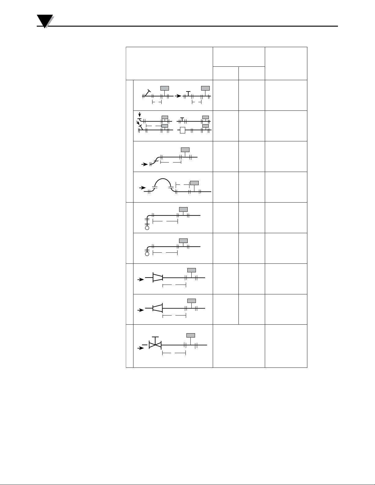
3. Run a length of straight pipe before and after the flow sensor probe. The
amount of upstream straight pipe required depends on the type of obstruction
which is immediately upstream of the flow sensor. See Table 1 (on next page)
for specific requirements. Downstream of the flow sensor, in all situations, run
5 diameters of straight pipe regardless of the downstream obstruction.
4. Align the sensor probe with the air flow. Make sure the air flow is
perpendicular to the sensor window. The score line on the sensor tubing
is another way of aligning the sensor to the flow stream. The score line
starts from the center of the sensor window and as a result it can be aligned
properly.
5. One way of installing the sensor probe into a flow stream is to utilize a
compression fitting such as Omega’s SSLK-14-14 stainless steel compression
fitting with Teflon ferrule, which allows adjustment of the insertion depth of
the probe.
Installation
2
6. Turn on the power switch and start measuring air velocity & temperature.
2-1
Page 8
2
Installation
Recommended
T ypical Piping Remarks
A
A
Straight Pipe
Length "A "
Withou t
V anes
15D 15 DC losed Branch
With
Va ne s
15D
15D
15D
15D
Elbow . Te e,
Branch Pipe
Long-radius
bend s
Elbow
Long-radius
bend s
Elbow
Long-radius
bend s
A
A
A
A
A
A
20D 15 D
25D 15D Elbow , 2 planes
25D 15 D
30D
25D
40D
35D
20D 15 DC ontracting Pip e
2-2
V aried Section Va lves Fittings in Tw o Planes All Fittings in Same Plan e
A
A
Note: Straight pipe length on the downstram side to be 5 pipe diameters minimum .
Note: D – Pipe internal diameter.
40D 20D Expanding Pipe
Recommend Mete r
Be Installed
Upstream
Regulating,
reducing valves
Ball, check valves
Shut-of f valves
Table 1. Piping Requirement
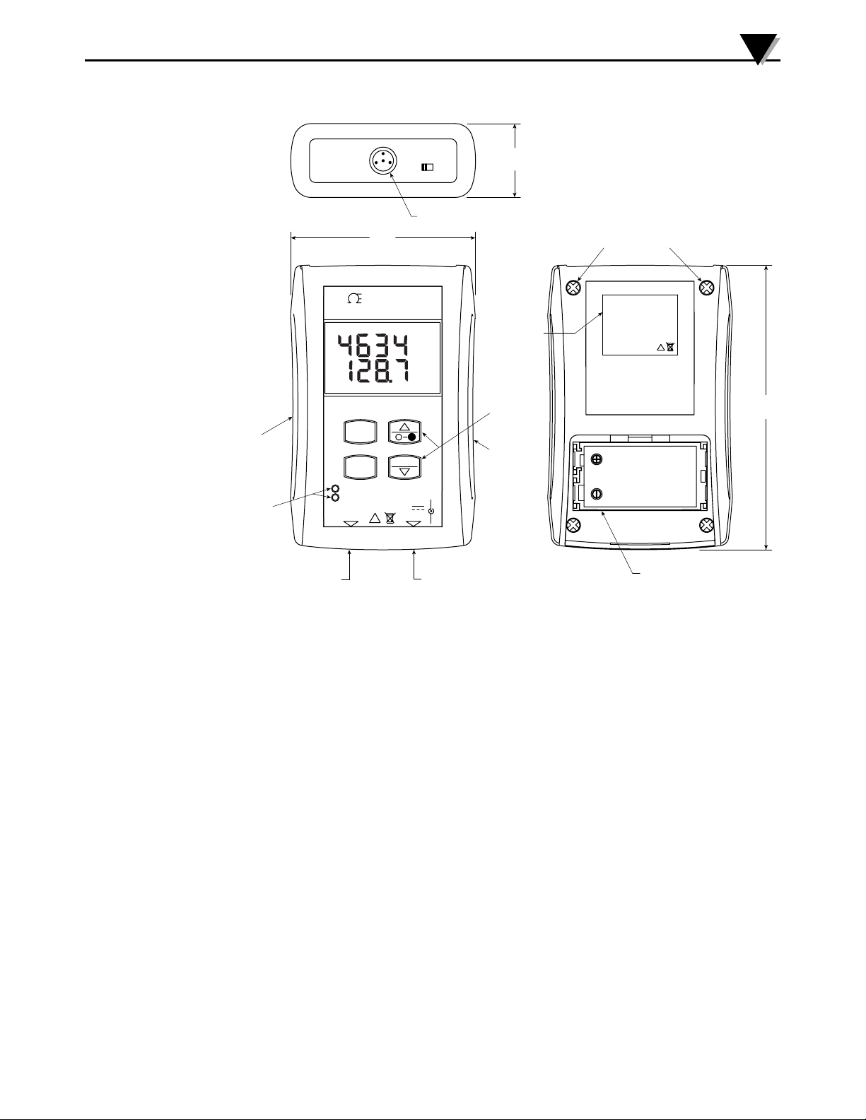
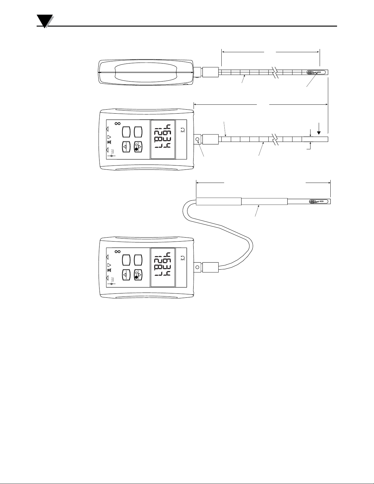
Figure 2-1 shows the general dimensions of the HHF1000 and all the controls.
Figure 2-2 shows the HHF1000 with fixed probe mount and remote telescopic
probe.
Page 9
PROBE
INPUT
77.77
(3.062)
31.75
POWER
O
I
33.27
(1.310)
(1.250)
AIR/TEMP PROBE CONNECTION
CASE SCREWS
Installation
DIMENSIONS mm (in)
2
RUBBER
BOOT
TRANSMIT
& RECEIVE
LEDs
(WIRELESS
VERSION)
OMEGA
HHF1000 SERIES
FPM
°F
AIR VELOCITY/TEMPERATURE
METER
BACK
LABEL
(WIRELESS
VERSION)
KEYPAD
FCC ID: OUR-XBEEPRO
IC #4214A-XBEEPRO
This device complies with Part 15 of the FCC
rules. Operation is subject to the following
two conditions:
1- This device may not cause harmful
interference.
2- This device must accept any interference
received, including interference that may
cause undesired operation.
Made in U.S.A.
MODE
RUBBER
BOOT
USB PC
INTERFACE
RX
TX
USB
PORT
SET
!
°F-°C
DC POWER
INPUT
9V
100mA
+
-
DC ADAPTER
INPUT
Figure 2-1. HHF1000 General Dimensions and Controls
C
!
FC
121.41
BATTERY COMPARTMENT
(ONE 9V SIZE BATTERY)
[BATTERY DOOR REMOVED]
120.65
(4.78)
(4.75)
2-3
Page 10
2
Installation
304.8
(12.0)
workable length
!
-
!
-
PORT
100mA
PORT
100mA
SCORE LINE FOR
FLOW ALIGNMENT
373.4
(14.7)
FIXED PROBE MOUNT
TX
RX
USB
SET
°F-°C
DC POWER
9V
INPUT
+
AIR VELOCITY/TEMPERATURE
MODE
METER
°F
HHF1000 SERIES
OMEGA
FPM
HHF1000 SERIES
LOCKING
BUTTON
AIR FLOW TO BE PERPENDICULAR
TO THE SENSOR WINDOW
1/4" OD 304 STAINLESS STEEL TUBING
WITH INCH MARKING
AIR VELOCITY/
TEMPERATURE SENSOR
AIR FLOW
EXTENDS FROM 254.0 (10) to 914.4 (36) inches
TELESCOPIC AIR/TEMP PROBE
TX
RX
USB
SET
°F-°C
DC POWER
9V
INPUT
+
AIR VELOCITY/TEMPERATURE
MODE
METER
HHF1000 SERIES
OMEGA
°F
FPM
2-4
DIMENSIONS mm (in)
Figure 2-2. HHF1000 Fixed Probe Mount and Remote Telescopic Probe
Page 11

Section 3 - Main Operation
The HHF1000 transmitter has a built-in LCD backlit display and keypad. Using
the display and keypad, you can view the following parameters:
• The air velocity & air temperature in real time (Main Display)
• Maximum air velocity & temperature during the session
• Minimum air velocity & temperature during the session
• Volume air flow in Cubic feet per minute (CFM) or Cubic meter per
minute (CMM)
You can view and set the following parameters from the keypad:
• High Alarm set point for air velocity
• Low Alarm set point for air velocity
• Display’s response time
• Cross sectional area of the air flow duct
• Atmospheric pressure setting in millimeter of Mercury (mmHg).
• Setting the Auto Power shut off feature to ON or OFF.
Main Operation
3
If the unit has wireless PC communication capability, you can view and set the
following parameters:
• Turn the Wireless Radio on or off.
• View the data transmission interval in seconds. You can change this
parameter from the End Device Configuration software.
• View the unit ID address. You can change this parameter from the End
Device Configuration software.
The wireless version communicates with the UWTC-REC1 wireless receiver. You
can transmit air velocity and air temperature data to the UWTC-REC1 and be
able to display and graph data on the TC central software application.
Changing Display Engineering Units - You can change the air velocity
Engineering unit display from Feet per minute (FPM) to meter per second (m/s),
miles per hour (MPH), and kilometers per hour (Km/h) from the keypad (Press
SET key). You can change the Temperature display from ºF to ºC or vise versa by
pressing the Down key.
Turn On Display Backlight - You can turn the LCD backlight on or off by
pressing the UP key. The backlight will turn off after 10 seconds if the UP key is
not pressed again.
High & Low Alarm Set Points - You can set and enable the high & low alarm set
points for the air velocity as shown in the keypad flow chart. When in the alarm
condition, the HAL or LAL icon will flash on the LCD.
Display Volume Air Flow - The unit calculates volume air flow by multiplying
the air velocity by the cross sectional area of the pipe or the duct. The cross
sectional area can be set in the display menu as shown in the keypad flow chart
in square inches units. The volume air flow is shown in Cubic feet per minute or
Cubic meter per minute when air temperature is displayed in Degrees C.
Auto Power Shutoff – You can turn on the auto power shutoff feature (Default
is ON) to save battery life. If no keys are pressed for 5 minutes, the unit will shut
down to save battery life. Pressing any key will turn the unit back on.
3-1
Page 12
3
-
-
MODE
°F-°C
-
Main Operation
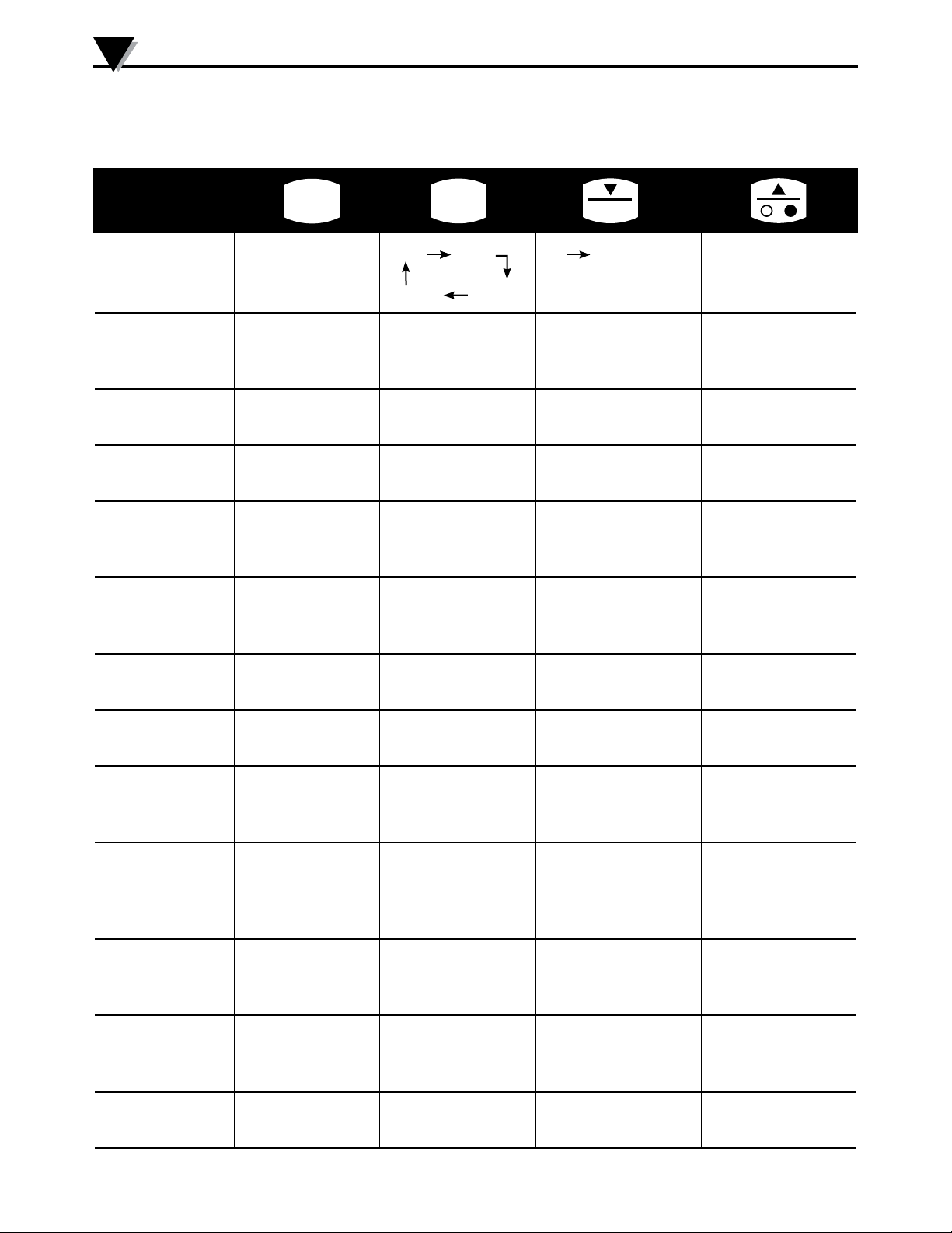
Table 2 shows the Keypad Functional Flow Chart.
MODE
Operation Press Press Press Press
SET
°F-°C
-
Real Time Go to Max FPM m/s °F °C or Turn On/off
Mode vice versa LCD Light
Km/h MPH
Display Max Vel. Go to Min ____________ _____________ Reset Max, Min,
& Temp MAX Icon Mode Velocity &
Temperature
Display Min Vel. Go to Volume ____________ _____________ Same
& Temp MIN Icon Air Flow Mode
Display Vol. Flow Go to High Alarm ____________ _____________ ____________
In CFM or CMM Mode Velocity
Display High Go to Low Enable/Disable Increment high Decrement high
Alarm Velocity Alarm Mode High Alarm, HAL Alarm Set Point Alarm Set Point
Set Point Velocity Icon when enabled
Display Low Go to Display Enable/Disable Increment Low Decrement Low
Alarm Velocity Response Time Low Alarm. LAL Alarm Set Point Alarm Set Point
Set Point Mode Icon When Enabled
Display LCD Go to Cross ____________ Increment Decrement
Response time Sec. Area Mode Response Time Response Time
Display Cross Go to Atmos. ____________ Increment Decrement
Sectional Area Sq In
Display AtPr & Go to Power Increment Decrement
mmHg Icon Shutoff Mode
Press. Mode Cross Sec. Area Cross Sec. Area
____________
Atmospheric Atmospheric
Pressure Pressure
Display Power Go to Real Time Turn On/off
Shutoff Mode OR Go to
____________
____________
Radio Mode
(Wireless)
Display Radio Go to Time Turn On/off
Mode Interval ____________ ____________
Transmission
Display Time Go to
Interval Transmission Unit
____________
____________
Transmission ID
Display Go to Real
Transmitter Unit ID Time Mode
3-2
Table 2. Keypad Functional Flow Chart
____________
____________
____________
____________
Page 13
Main Operation
AREA DISPLAY MODE
NOTE:
The HHF1000 air velocity/temperature meter saves the
following parameters in the non-volatile memory, so
removing the power will not affect these settings:
High & Low alarm air velocity set points & status (On or
Off) Display Response time in msec, Cross sectional area in
Square inches, Atmospheric Pressure in mmHg
3
PRESS
SET
PRESS
SET
TO ENABLE/
DISABLE HIGH
ALARM
PRESS
SET
TO ENABLE/
DISABLE LOW
ALARM
TO CHANGE RESPONSE
REAL TIME MODE (MPH)
REAL TIME MODE (m/s)
PRESS
MODE
PRESS
MODE
PRESS
MODE
PRESS
TO CHANGE HIGH
ALARM SET POINT
PRESS
MODE
PRESS
TO CHANGE LOW
ALARM SET POINT
PRESS
MODE
PRESS
TIME
PRESS
SET
MPH
°F
PRESS
PRESS
MAX
HAL
MAX
MODE
MIN
LAL
SET
FPM
°F
FPM
°F
FPM
FPM
m/s
m/s
°F
MAXIMUM DISPLAY MODE
MINIMUM DISPLAY MODE
VOLUME AIR FLOW MODE
HIGH ALARM DISPLAY MODE
LOW ALARM DISPLAY MODE
DISPLAY RESPONSE TIME MODE
°F
REAL TIME MODE (Km/h)
FPM
°F
REAL TIME MODE
MAIN MENU
WIRELESS TRANSMITTER UNIT
CFM
STANDARD (NON-WIRELESS) MODEL
WIRELESS RADIO DISPLAY MODE
MODE
PRESS
PRESS
MODE
Km/h
PRESS
SET
PRESS
°F-°C
PRESS
MODE
ID DISPLAY MODE
TRANSMISSION INTERVAL
DISPLAY MODE
AUTO POWER SHUT OFF
DISPLAY MODE
ATMOSPHERIC PRESSURE
DISPLAY MODE
CROSS SECTIONAL
mmHg
FPM
°C
REAL TIME MODE (°C)
PRESS
MODE
PRESS
MODE
SET
PRESS
TO TURN ON/OFF
THE RADIO
PRESS
MODE
SET
PRESS
TO ENABLE/DISABLE
AUTO POWER SHUT OFF
PRESS
MODE
PRESS
TO CHANGE
ATMOSPHERIC
PRESSURE
PRESS
MODE
PRESS
TO CHANGE CROSS
SECTIONAL AREA
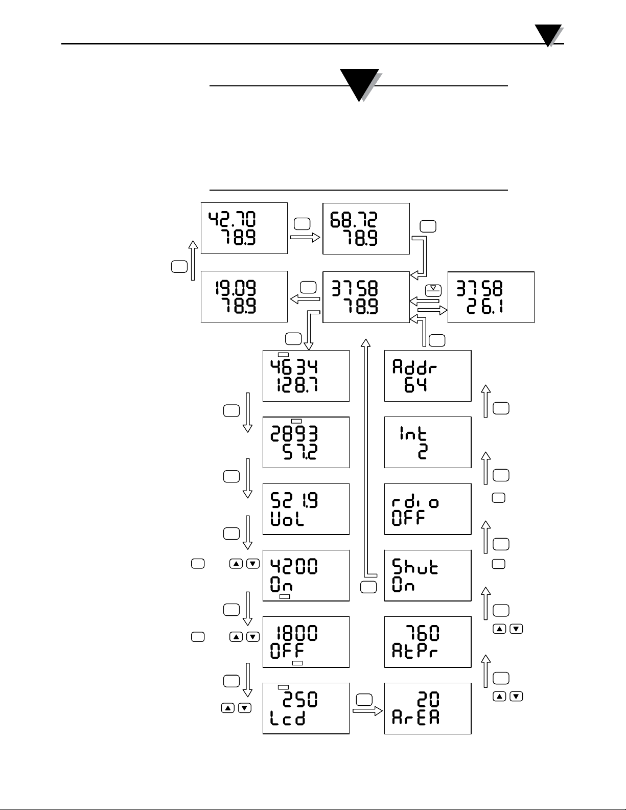
Figure 3-1. Display Functional Flow Chart
3-3
Page 14

4
PC Interface
Section 4 - PC Interface
The HHF1000 series comes with a Windows based user application. This
application runs on Windows XP, Vista, and Seven. It allows you to perform the
following functions:
• Monitor and display the air velocity and temperature in real time, including
line graph of the two channels.
• Display the air velocity and temperature in different Engineering units
• Change the upper and lower values for the two channels from auto, to manual.
or logarithmic scale.
• Change the chart time base from 1 minute to 10 minutes, and one hour.
• Save the air velocity and temperature data to a file.
• Print the air velocity and temperature graphs to a printer.
Operation
• Install the user application.
• Connect the USB cable provided between the HHF1000 and the PC. For
wireless version, make sure the radio is turned off.
• When the HHF1000 is connected to the PC for the first time, the PC recognizes
the unit and it looks for the USB drivers. The necessary drivers are on the
same CD.
The “Found new hardware wizard” program will open. Select “Install from the
specific location” option and select the program CD where the drivers are located.
4-1
You are now ready to run the application. When the application is run, it establishes
communication with the HHF1000 meter, and a “Go” button will show up on the
Main window. Clicking the “Go” button will start the data logging session.
If the application can not establish communication, it will show an error message
box, and the “Find” button will flash. Please check for the following:
• The meter is connected to a USB port of the PC
• Go to Settings menu and check the COM port number. Make sure you are
using the right COM port on your PC. Choose 9600 for COM Baud Rate.
You can check the connected COM port by opening the Device Manager
(From the system properties) and review all the COM ports.
• Click the “Find” button, and the program should be able to establish
communication. The “Find” button will change to “Go”.
• Click the “Go” button, and the program will start to log data in real time. The
display update is every 250 msec.
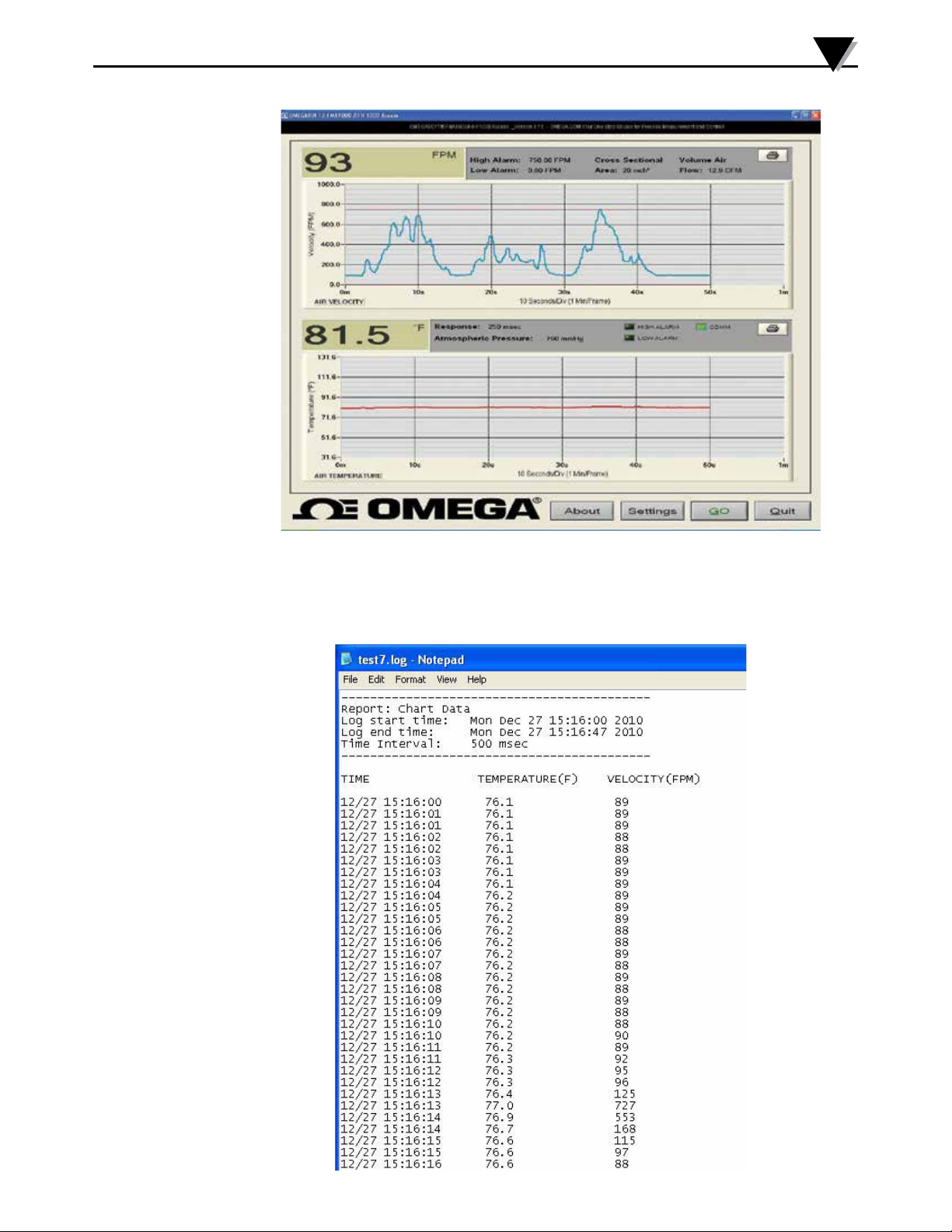
Figure 4-1 shows the Main window after logging some data. The main window
shows the following:
• Display of line graph and digital values of air velocity and temperature in real time.
• Display high & low alarm lines and values for velocity
• Display response time in msec, volume air flow in CFM, cross sectional area in
square inches, and the atmospheric pressure in mmHg.
• High & low alarm LED indicators for the velocity channel. The LED indicator
will turn red when in alarm condition.
• Communication LED indicator. This is a flashing Green LED indicator to show
good communication. If there is no communication, this LED will not flash.
Page 15
PC Interface
4
Figure 4-1. Main Window Screen
You can save the logged data into a data file. This file can be imported into Excel
spread sheet for further analysis. Figure 4-2 shows a typical data file. You can
save up to 144,000 sets of velocity and temperature data.
Figure 4-2. Typical Data File Screen
4-2
Page 16
4
PC Interface
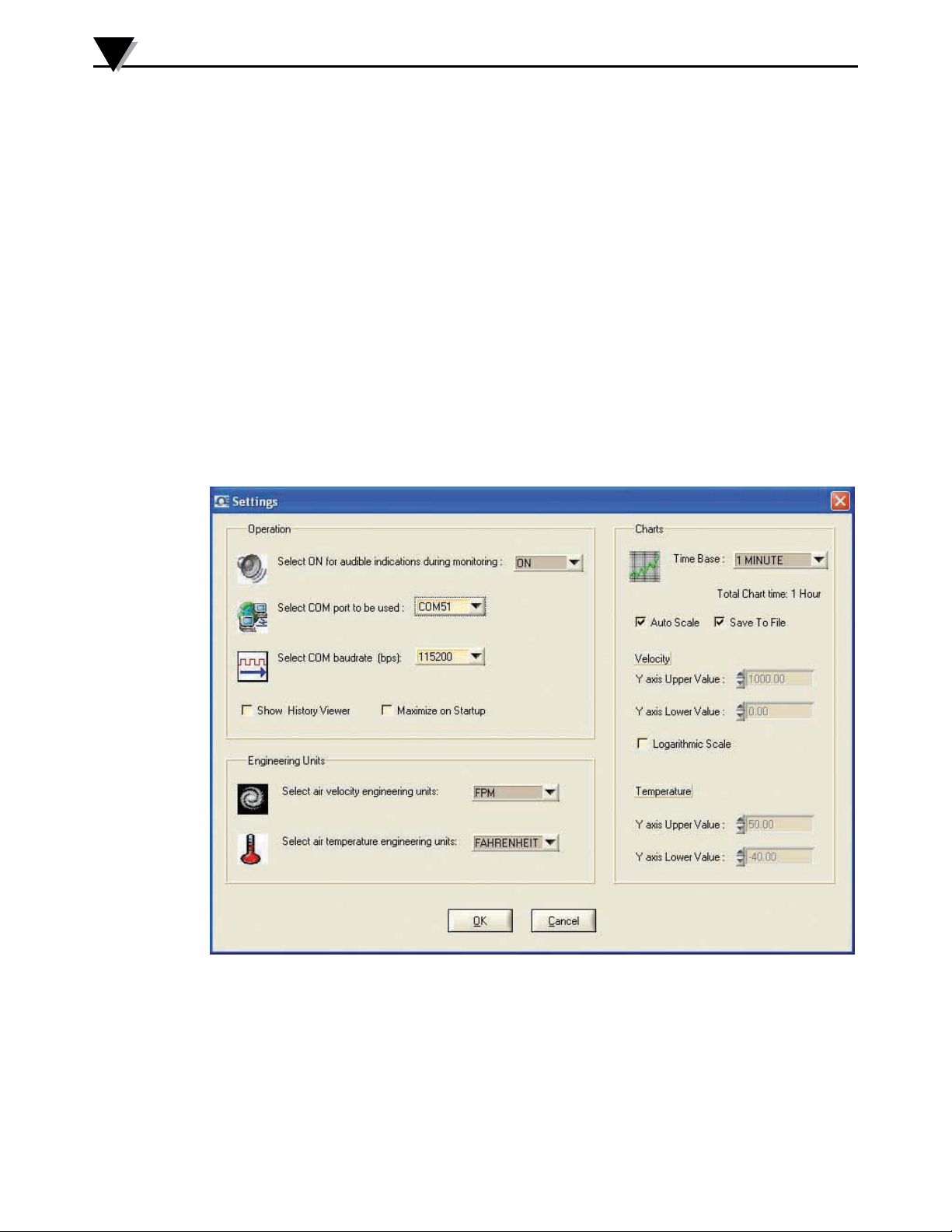
Figure 4-3 shows the Settings menu. You can set the following parameters:
• COM port number on your PC.
• Baud rate selection (9600 or 115200) Select 9600 for the HHF1001/
HHF1001W.
• Turn the audible indicator on/off.
• Engineering units for air velocity and temperature
• Select chart time base from 1 minute per frame (screen), 10 minutes, or
one hour.
• Select manual, auto, or logarithmic scale of the air velocity or
temperature. This function allows the user to set the Y scale for the air
velocity and temperature to any value within its range.
• Select Save to file, History viewer, and Maximize start up.
When the “Save to File” is selected (Default), the program asks if you would
like to save the data to a file when you stop the data logging, Figure 4-2 shows a
typical data file saved.
4-3
Figure 4-3. Settings Menu Screen
Maintenance
Except for intermittent removal of the sensor from the line for cleaning, there is
no routine maintenance for the HHF1000. If the sensor probe becomes coated
with dust, blow the dust away with clean air. If the sensor probe is coated with
sticky material, clean it with water or alcohol (Ethanol) using an artist’s brush.
Calibration
Each HHF1000 is individually calibrated in a NIST traceable wind tunnel. For
calibration certification or calibrating to a new air flow range, the unit must be
returned back to the factory.
Page 17
Wireless PC Communications
Section 5 - Wireless PC Communications
The HHF1000 offers wireless PC communication on some of its models
(HHF1001x-W). The unit has a built-in wireless module and it can transmit air
velocity and air temperature in real time to our UWTC-REC1 wireless receiver.
The UWTC-REC1 then sends the incoming data to the PC. You can monitor
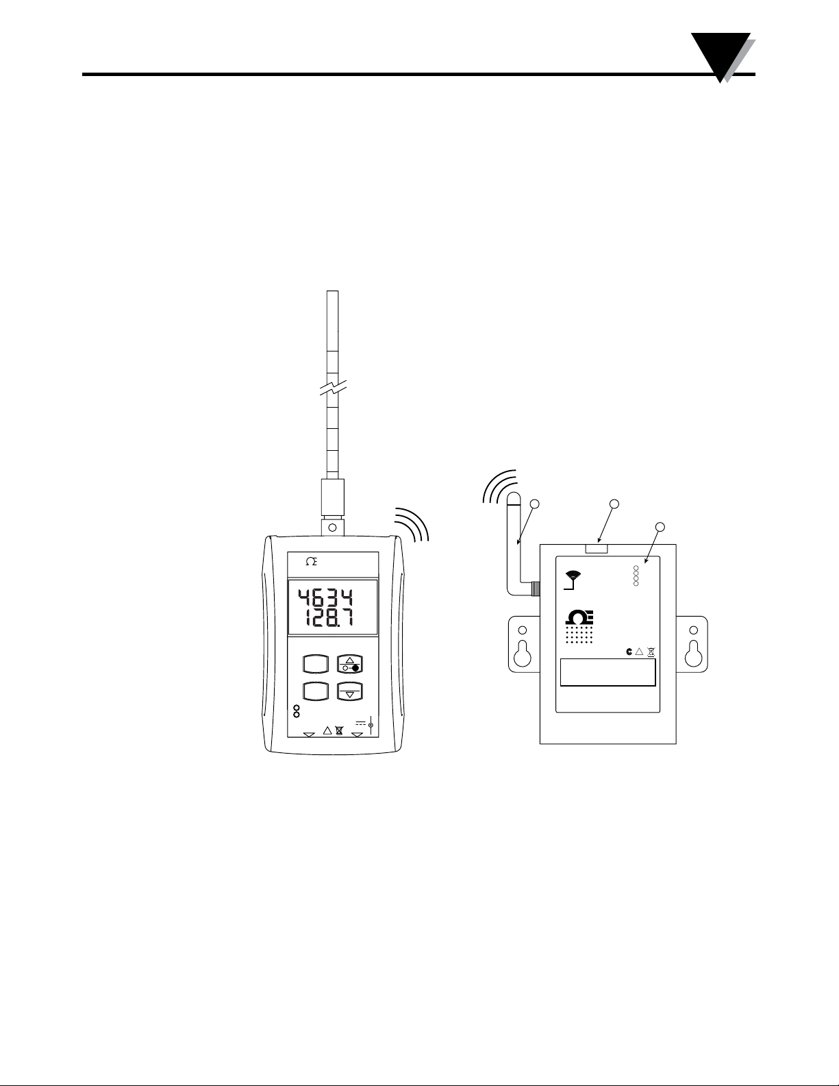
and log the data from the TC central software application. Figure 5-1 shows the
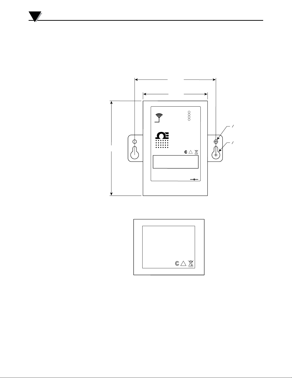
HHF1000 & UWTC-REC1 wireless system. Figure 5-2 (on next page) shows the
wireless receiver general & mounting dimensions. Figure 5-3 (on next page)
shows the FCC warning label of the HHF1000 wireless transmitter.
5
2
USB
UWTC SERIES
2.4 GHz
F
Made in U.S.A.
TX
RX
SB
PWR
!
omega.com
3
OMEGA
HHF1000 SERIES
FPM
°F
AIR VELOCITY/TEMPERATURE
METER
MODE
°F-°C
SET
RX
USB
PORT
!
DC POWER
INPUT
9V
100mA
TX
1
ANTENNA
WIRELESS RF RECEIVER
®
FCC ID: OUR–XBEEPRO
IC #4214A–XBEEPRO
This device complies with Part 15 of the FCC rules.
Operation is subject to the following two conditions:
1) This device may not cause harmful interference;
2) This device must accept any interference received,
including interference that may cause undesired
operation.
OMEGA ENGINEERING, INC.
Stamford, CT 06907
+
-
Figure 5-1. HHF1000 and UWTC-REC1 Wireless System
(1) Antenna
(2) USB PC Connector
(3) Indicator Lights as follows:
Transmit (TX) Green indicator light - The top green indicator light marked “TX”
on the front of the receiver will only blink when the receiver is connected to your
PC and you initialize your measurement software. After the receiver establishes
communication with the program, the light will no longer blink. Note this may
happen very fast and will not be noticeable.
Receiver (RX) red indicator light - The red indicator light marked “RX” on the
front of the receiver will blink each time the receiver receives incoming data
from one of the wireless transmitters.
5-1
Page 18
5
ANTENNA
USB
I/O
9–24 Vdc
OMEGA ENGINEERING, INC.
Stamford, CT 06907
UWTC SERIES
WIRELESS RF RECEIVER
2.4 GHz
omega.com
Made in U.S.A.
-
+
!
TX
RX
SB
PWR
This device complies with Part 15 of the FCC rules.
Operation is subject to the following two conditions:
1) This device may not cause harmful interference;
2) This device must accept any interference received,
including interference that may cause undesired
operation.
FCC ID: OUR–XBEEPRO
IC #4214A–XBEEPRO
F
®
64 (2.5)
89 (3.5)
DIMENSIONS mm (in)
o 3.6
(0.140)
o 7.5
(0.295)
76 (3.0)
Mounting Hole Center Line
!
F
FCC ID: OUR-XBEEPRO
IC #4214A-XBEEPRO
Made in U.S.A.
This device complies with Part 15 of
the FCC rules. Operation is subject to
the following two conditions:
1. This device may not cause harmful
interference.
2. This device must accept any
interference received, including
interference that may cause
undesired operation.
Wireless PC Communications
Standby (SB) yellow indicator light - The yellow indicator light marked “SB” on
the front of the receiver will blink continuously during normal operation. This
indicates that the receiver is in Standby mode and is waiting for incoming data
from the wireless transmitter.
Power (PWR) Green indicator light is for power indication.
5-2
Figure 5-2. General And Mounting Dimensions
The HHF1000 series comes with an additional Windows based user application.
This program, TC Central, is used to monitor and log air velocity and air
temperature wirelessly from the HHF1000 device. In addition, from the
"Tools" menu, you can select "Configure End Device...", to Run the End Device
Configuration Wizard. You can set the unit ID (Transmitter Address) and data
transmission interval using this feature.
Figure 5-3. FCC Warning Label
Page 19
5.1 End Device Configuration
The wireless transmitter (HHF1001x-W) has the following default settings:
Data Transmission time interval: 2 seconds
Unit ID Address: 01
You can change the transmission interval and the unit ID address of the wireless
transmitter using this software application. Connect the wireless transmitter
to the PC USB port with the cable provided. Run the End device configuration
software. The software will recognize the transmitter and allows the settings
to be changed. You can set the data transmission interval from 1 to 60 seconds.
You can have up to 48 wireless transmitters sending data to one wireless
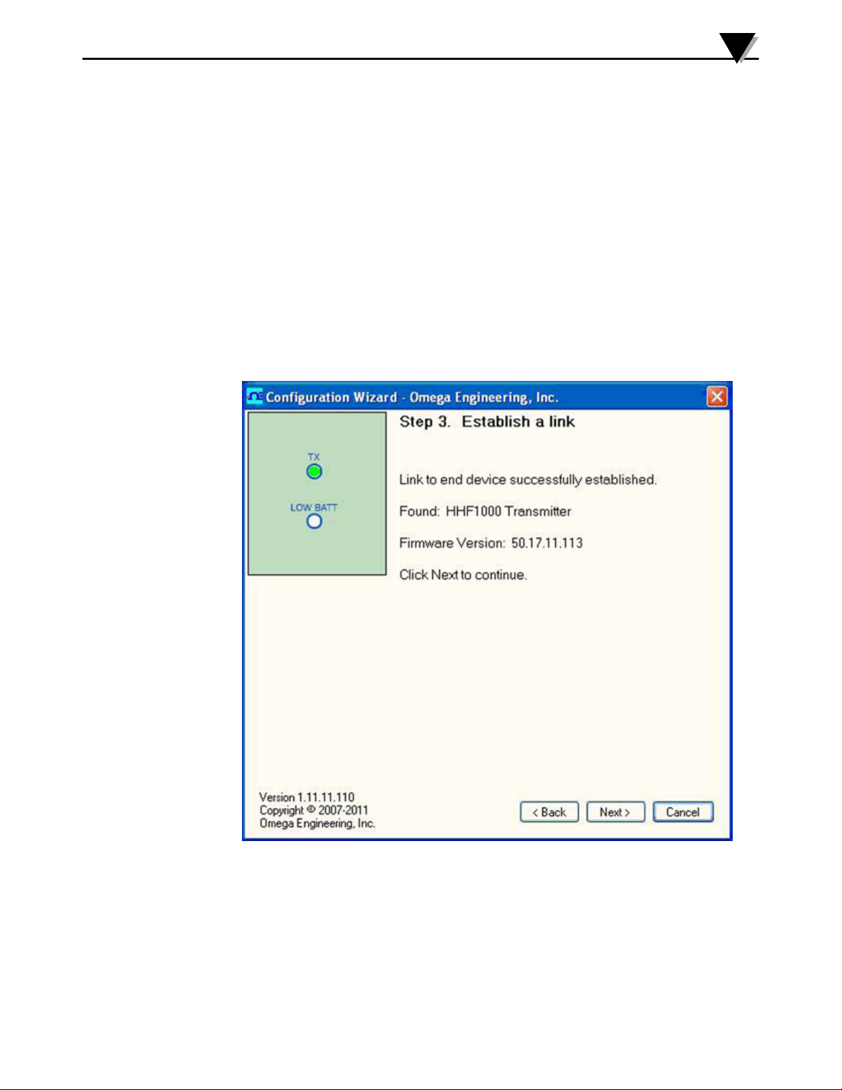
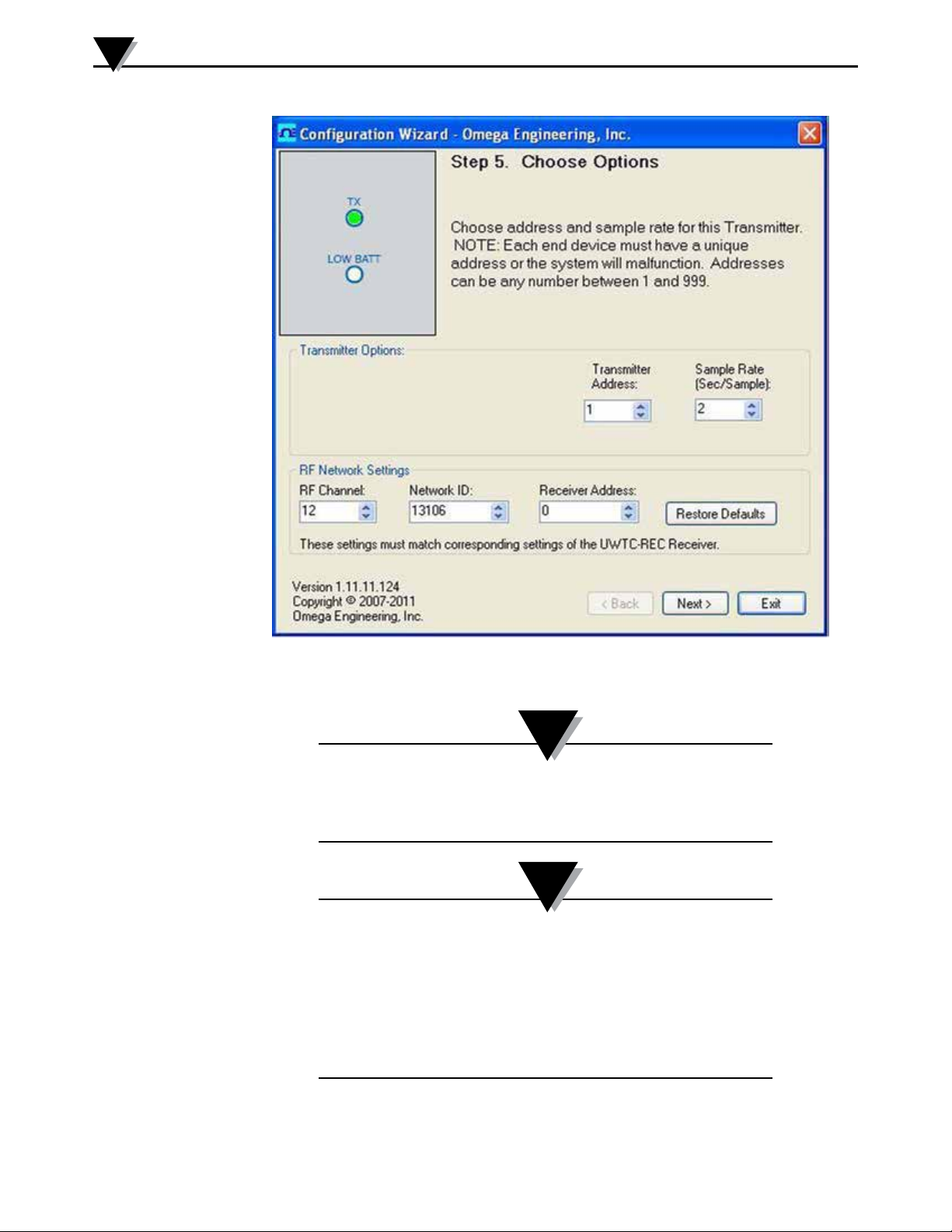
receiver. Figure 5-4 shows the End Device Configuration software establishing
communication with HHF1000. Figure 5-5 shows the Options menu where you
can change the Unit ID and the data sampling rate.
Wireless PC Communications
5
Figure 5-4. Establishing Communication With HHF1000 Screen
5-3
Page 20
5
Wireless PC Communications
Figure 5-5. Options Menu Screen
NOTE:
The wireless transmitter (HHF1001X-W) will not transmit
when connected to the USB port of a PC. You must disconnect
the transmitter from the PC for wireless transmission.
NOTE:
1. If the sensor probe is disconnected, or any sensor failure,
the red LED blinks 3 times every 15 seconds.
2. If there is an RF communication failure, the red LED blinks
once every 15 seconds.
3. If there is a sensor failure and RF communication failure at
the same time, the red LED blinks 4 times every 15
seconds.
5-4
Page 21
5.2 TC Central
Once the wireless transmitter is set using the end device configuration software,
connect the wireless receiver (UWTC-REC1) to the PC USB port. Then run the
TC central software. The software will recognize and connect to the wireless
receiver. You can now monitor and log air velocity and air temperature from the
wireless transmitter (HHF1001x-W).
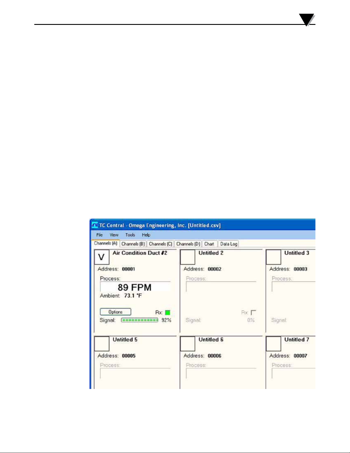
Figure 5-6 shows the main menu where air velocity, air temperature, and
wireless signal strength are displayed in real time. Please note that since the
HHF1000 is set for unit ID #1, it is displayed under Address 0001.
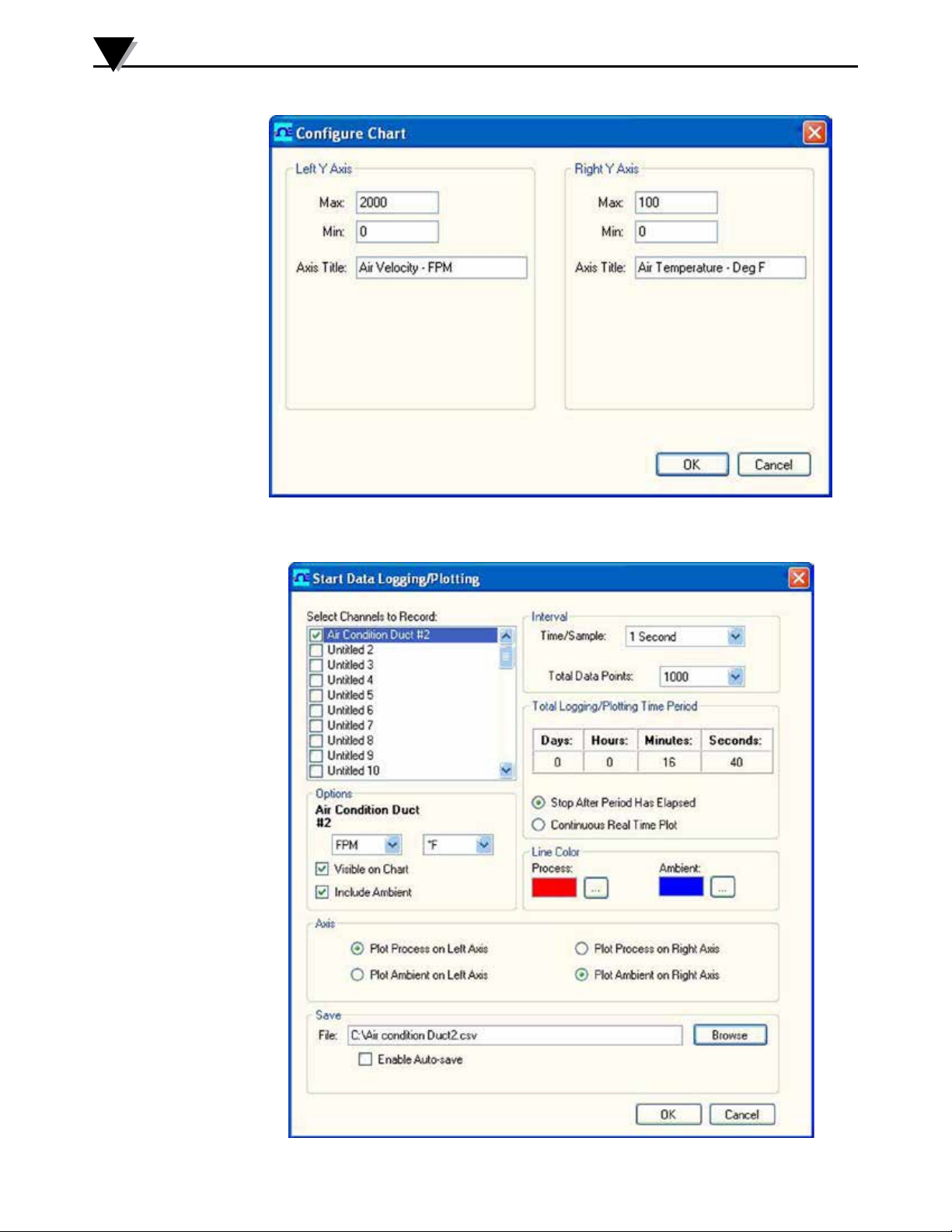
You can configure the left and the right Y Axis for air velocity and temperature
by clicking the options button. Figure 5-7 shows the configuration of the Y Axis.
You can chart and log data in real time. Simply click on the chart tab from the
main menu.
After configuring the Y Axis, click on the start button from the chart tab menu.
It will take you to the Data Plotting/Logging Menu selection as shown in Figure
5-8. In this menu, you can select chart sampling rate, line colors, plotting on left
and right axis, and the location of the data file. After you are done, click OK to
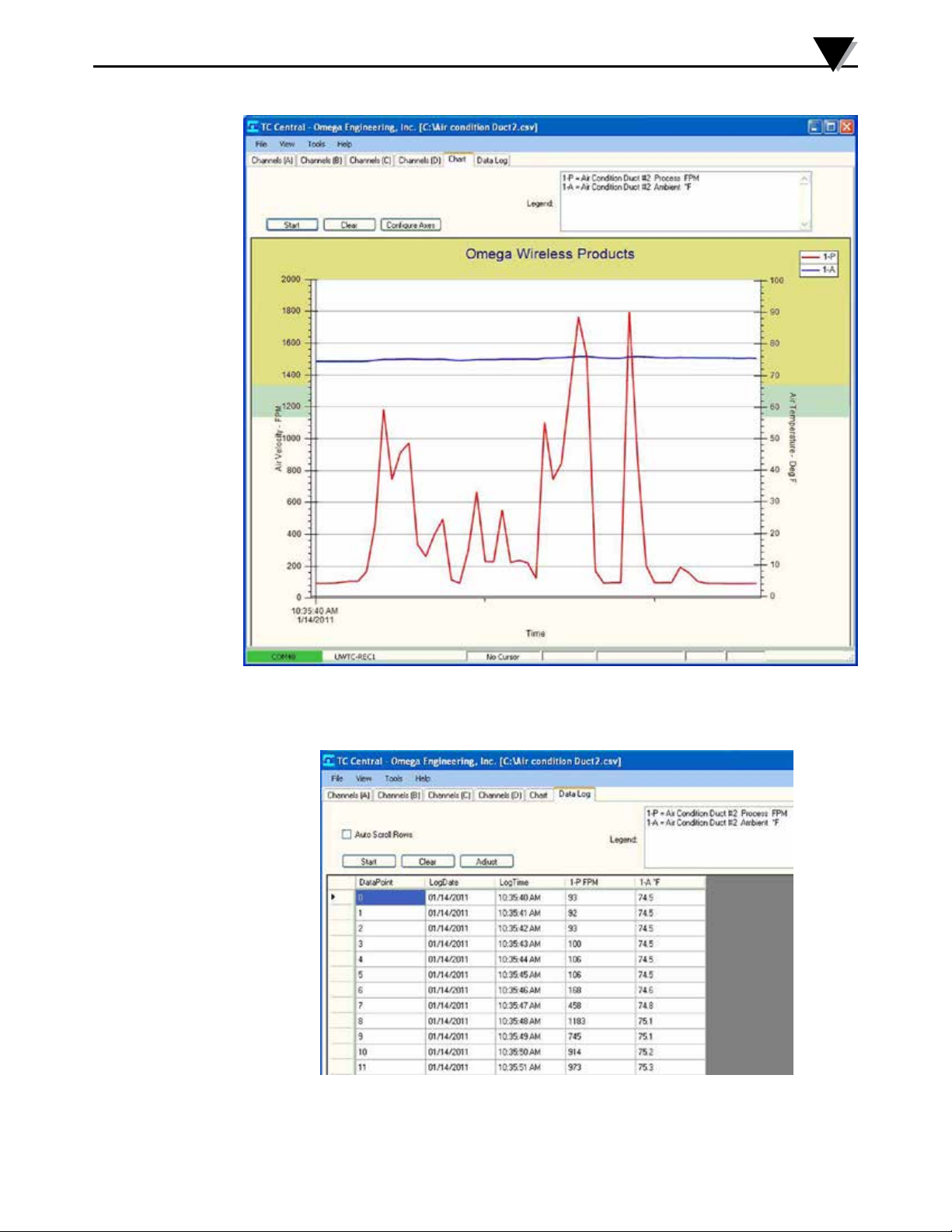
go back to the plotting screen. You will see the air velocity and air temperature
plots in real time as shown in Figure 5-9.
Wireless PC Communications
5
You can view the data log by clicking the Data Log tab. Figure 5-10 shows the
data log screen.
Figure 5-6. TC Central Main Menu Screen
5-5
Page 22
5
Wireless PC Communications
Figure 5-7. Y Axis Configuration Screen
5-6
Figure 5-8. Data Plotting/Logging Menu Selection Screen
Page 23
Wireless PC Communications
5
Figure 5-9. Air Velocity/Temperature Plot In Real Time Screen
Figure 5-10. Data Log Screen
5-7
Page 24

6
Specifications
Section 6 - Specifications
GENERAL
Range
Air Velocity: 0-5000 FPM (0 to 25.4 m/sec)
Air Temperature: -40 to 93ºC (-40 to 199ºF)
Accuracy
Air Velocity: 1.5% Full scale
Air Temperature: 0.5% Full scale
Display Resolution
Air Velocity: 1 FPM, 0.01 m/s, 0.01 MPH, 0.01 Km/h
Air Temperature: 0.1 Degree
Sensor Probe
Standard: 6.3 OD x 305 mm (1⁄4 OD x 12") –
workable length 304 Stainless Steel
Remote Telescopic: 6.3 OD x Adjustable from 254 to 914mm
(1/4 OD x 10 to 36") – 304 Stainless Steel
Velocity/Temperature Sensor: One 100 ohms RTD, Two 1000 ohms RTD
Response Time: 250 msec default - 0 to 90% Display Final value
(Programmable from 250 msec to 2 seconds)
Calculated Air Velocity Values: Maximum & Minimum, 250 msec response time
Calculated Temperature Values: Maximum & Minimum, 250 msec response time
Calculated Volume Air Flow: Displays in cubic feet per minute (CFM) or
cubic meters per minute (CMM)
Cross Sectional Area: 20 Sq-Inches default
Programmable from 1 to 400 Sq-Inches via
keypad
High Alarm Set Point, Velocity: Maximum range default –
Programmable via keypad
Low Alarm Set Point, Velocity: Minimum Range default –
Programmable via keypad
High & Low Alarm Indication: HAL or LAL icon flashes on the display
Alarm Deadband: 25 FPM
Power: 9V Lithium Battery, or ac adapter
Battery Life: 6 Hours, continuous
Low Battery Indication BAT Icon on the LCD
6-1
AC Adapter: 100 to 240 Vac, 50-60 Hz UL, CE, FCC Marking
Output Voltage: 9V @ 1.7A
Output Plug (Female): Center positive, coax 2.0/5.5/10mm
Operating Ambient Temperature
Sensor Probe: -40 to 93ºC (-40 to 199ºF)
Meter: 0 to 50ºC (32 to 122ºF)
Operating Relative Humidity: 0 to 95% RH without condensation
Page 25

Specifications
6
Meter Case: ABS Plastic
PC Interface: USB , 9600 baud rate, 8 bit data
No parity, 1 stop bit
General Dimensions (Case): 121.4 L x 77.7 W x 33.2 mm D
(4.78 x 3.06 x 1.31”)
Weight: 300g (0.66 lbs)
WIRELESS PC INTERFACE
Wireless Transmitter, HHF1001x-W
RF Transmitter Carrier: ISM 2.4GHz. Direct sequence spread spectrum,
License free worldwide (US, Canada, and
Europe)
RF Power Output: 10 dBm (10 mW)
RF Range
Indoor/Urban: Up to 40m (130')
Outdoor/Line of Sight: Up to 120m (400')
LED Indicators: Green TX LED (Transmit), Red RX LED
(Receive)
Data Transmission Interval: 2 seconds default, Settable from 1 to 60
seconds through End Device Configuration
software
Unit ID Address: Default is 1. Settable from 1 to 48 through End
Device Configuration software
Wireless Receiver, UWTC-REC1
Power: USB +5V Powered, 300 mA max.
USB Compatibility: USB 1.1, USB 2.0
LED Indicators: TX (transmit) RX (receive) SB (Standby) PWR
(USB Power)
Radio Frequency (RF): ISM 2.4 GHz, direct sequence spread
(US, Canada, and Europe)
Protocol: IEEE 802.15.4
Cable Type: USB 4P(A) Male to USB Mini 5P(B) Male
Ambient Operating Conditions: -10 to 70°C, 0-95% Relative Humidity
(Non-condensing)
6-2
Page 26
7
Approvals, Regulatory Compliance
Section 7 - Approvals, Regulatory Compliance
FCC (Domestic Use: USA & Canada)
(USA) FCC ID: OUR-XBEEPRO (CANADA) IC #4214A-EXBEEPRO
This device complies with Part 15 of the FCC rules. Operation is subject to the
following two conditions:
1.) This device may not cause harmful interference.
2.) This device must accept any interference received, including interference that
may cause undesired operation.
WARNING:
To satisfy FCC RF exposure requirements for mobile
transmitting devices, a separation distance of 20 cm or more
should be maintained between this device and persons during
device operation. To ensure compliance, operations at closer
than this distance is not recommended. This transmitter must
not be co-located in conjunction with any other transmitter or
antenna.
7.1 Environment/Operating Conditions
The wireless transmitter and receiver modules have been designed to be
operated in a clean and dry indoor environment. Care should be taken to
prevent the components of your wireless system from being exposed to
moisture, toxic chemicals and extreme cold or hot temperature that are outside
the specifications listed in this manual.
7.1.1 Operating Conditions
The following is a list of basic good practice you should apply when operating
your wireless system.
• Never operate your wireless device outside the recommended environmental
limits specified in this manual.
• Never operate your wireless device in flammable or explosive environments.
• Never use your wireless device in medical, nuclear or other dangerous
applications where failure can cause damage or harm.
• No co-location with other radio transmitters is allowed. By definition,
co-location is when another radio device or it’s antenna is located within 20
cm of your transmitter and can transmit simultaneously with your unit.
• Never install receiver/transmitters within 20 cm or less from each other.
7-1
• Never install and/or operate your transmitter/receiver closer than 20 cm to
nearby persons.
Page 27

WARRANTY/DISCLAIMER
OMEGA ENGINEERING, INC. warrants this unit to be free of defects in materials and workmanship for a
period of 13 months from date of purchase. OMEGA’s WARRANTY adds an additional one (1) month
grace period to the normal one (1) year product warranty to cover handling and shipping time. This
ensures that OMEGA’s customers receive maximum coverage on each product.
If the unit malfunctions, it must be returned to the factory for evaluation. OMEGA’s Customer Service
Department will issue an Authorized Return (AR) number immediately upon phone or written request.
Upon examination by OMEGA, if the unit is found to be defective, it will be repaired or replaced at no
charge. OMEGA’s WARRANTY does not apply to defects resulting from any action of the purchaser,
including but not limited to mishandling, improper interfacing, operation outside of design limits,
improper repair, or unauthorized modification. This WARRANTY is VOID if the unit shows evidence of
having been tampered with or shows evidence of having been damaged as a result of excessive corrosion;
or current, heat, moisture or vibration; improper specification; misapplication; misuse or other operating
conditions outside of OMEGA’s control. Components in which wear is not warranted, include but are not
limited to contact points, fuses, and triacs.
OMEGA is pleased to offer suggestions on the use of its various products. However,
OMEGA neither assumes responsibility for any omissions or errors nor assumes liability for
any damages that result from the use of its products in accordance with information provided
by OMEGA, either verbal or written. OMEGA warrants only that the parts manufactured by the
company will be as specified and free of defects. OMEGA MAKES NO OTHER WARRANTIES OR
REPRESENTATIONS OF ANY KIND WHATSOEVER, EXPRESSED OR IMPLIED, EXCEPT THAT OF
TITLE, AND ALL IMPLIED WARRANTIES INCLUDING ANY WARRANTY OF MERCHANTABILITY
AND FITNESS FOR A PARTICULAR PURPOSE ARE HEREBY DISCLAIMED. LIMITATION OF
LIABILITY: The remedies of purchaser set forth herein are exclusive, and the total liability of
OMEGA with respect to this order, whether based on contract, warranty, negligence,
indemnification, strict liability or otherwise, shall not exceed the purchase price of the
component upon which liability is based. In no event shall OMEGA be liable for
consequential, incidental or special damages.
CONDITIONS: Equipment sold by OMEGA is not intended to be used, nor shall it be used: (1) as a “Basic
Component” under 10 CFR 21 (NRC), used in or with any nuclear installation or activity; or (2) in medical
applications or used on humans. Should any Product(s) be used in or with any nuclear installation or
activity, medical application, used on humans, or misused in any way, OMEGA assumes no responsibility
as set forth in our basic WARRANTY/DISCLAIMER language, and, additionally, purchaser will indemnify
OMEGA and hold OMEGA harmless from any liability or damage whatsoever arising out of the use of the
Product(s) in such a manner.
RETURN REQUESTS/INQUIRIES
Direct all warranty and repair requests/inquiries to the OMEGA Customer Service Department.
BEFORE RETURNING ANY PRODUCT(S) TO OMEGA, PURCHASER MUST OBTAIN AN AUTHORIZED
RETURN (AR) NUMBER FROM OMEGA’S CUSTOMER SERVICE DEPARTMENT (IN ORDER TO AVOID
PROCESSING DELAYS). The assigned AR number should then be marked on the outside of the return
package and on any correspondence.
The purchaser is responsible for shipping charges, freight, insurance and proper packaging to prevent
breakage in transit.
FOR WARRANTY RETURNS, please have the
following information available BEFORE
contacting OMEGA:
1. Purchase Order number under which the product
was PURCHASED,
2. Model and serial number of the product under
warranty, and
3. Repair instructions and/or specific problems
relative to the product.
OMEGA’s policy is to make running changes, not model changes, whenever an improvement is possible. This affords
our customers the latest in technology and engineering.
OMEGA is a registered trademark of OMEGA ENGINEERING, INC.
© Copyright 2017 OMEGA ENGINEERING, INC. All rights reserved. This document may not be copied, photocopied,
reproduced, translated, or reduced to any electronic medium or machine-readable form, in whole or in part, without the
prior written consent of OMEGA ENGINEERING, INC.
FOR NON-WARRANTY REPAIRS,
for current repair charges. Have the following
information available BEFORE contacting OMEGA:
1. Purchase Order number to cover the COST
of the repair,
2. Model and serial number of the product, and
3. Repair instructions and/or specific problems
relative to the product.
consult OMEGA
Page 28

Where Do I Find Everything I Need for
Process Measurement and Control?
OMEGA…Of Course!
Shop online at omega.com
TEMPERATURE
MU
Thermocouple, RTD & Thermistor Probes, Connectors, Panels & Assemblies
MU
Wire: Thermocouple, RTD & Thermistor
MU
Calibrators & Ice Point References
MU
Recorders, Controllers & Process Monitors
MU
Infrared Pyrometers
PRESSURE, STRAIN AND FORCE
MU
Transducers & Strain Gages
MU
Load Cells & Pressure Gages
MU
Displacement Transducers
MU
Instrumentation & Accessories
FLOW/LEVEL
MU
Rotameters, Gas Mass Flowmeters & Flow Computers
MU
Air Velocity Indicators
MU
Turbine/Paddlewheel Systems
MU
Totalizers & Batch Controllers
SM
pH/CONDUCTIVITY
MU
pH Electrodes, Testers & Accessories
MU
Benchtop/Laboratory Meters
MU
Controllers, Calibrators, Simulators & Pumps
MU
Industrial pH & Conductivity Equipment
DATA ACQUISITION
MU
Communications-Based Acquisition Systems
MU
Data Logging Systems
MU
Wireless Sensors, Transmitters, & Receivers
MU
Signal Conditioners
MU
Data Acquisition Software
HEATERS
MU
Heating Cable
MU
Cartridge & Strip Heaters
MU
Immersion & Band Heaters
MU
Flexible Heaters
MU
Laboratory Heaters
ENVIRONMENTAL
MONITORING AND CONTROL
MU
Metering & Control Instrumentation
MU
Refractometers
MU
Pumps & Tubing
MU
Air, Soil & Water Monitors
MU
Industrial Water & Wastewater Treatment
MU
pH, Conductivity & Dissolved Oxygen Instruments
M4979/0817
 Loading...