

Page 1
HHEM-SD1
Environment Meter
with Data Logging SD Card
e-mail: [email protected]
For latest product manuals:
omegamanual.info
Shop online at
omega.com
®
User’s Guide
®
MADE IN TAIWAN
Page 2

Servicing North America:
U.S.A.: OMEGA Engineering, Inc.
ISO 9001 Certified One Omega Drive
P.O. Box 4047
Stamford, CT 06907-0047 USA
Toll-Free: 1-800-826-6342 TEL: (203) 359-1660
FAX: (203) 359-7700 e-mail: [email protected]
Canada: 976 Bergar
Laval (Quebec), H7L 5A1 Canada
Toll-Free: 1-800-826-6342 TEL: (514) 856-6928
FAX: (514) 856-6886 e-mail: [email protected]
For immediate technical or application assistance:
U.S.A. and Canada: Sales Service: 1-800-826-6342/1-800-TC-OMEGA
®
Customer Service: 1-800-622-2378 /1-800-622-BEST
®
Engineering Service: 1-800-872-9436/1-800-USA-WHEN
®
Mexico/ En Español: 001 (203) 359-7803 FAX: 001 (203) 359-7807
Latin America [email protected] e-mail: [email protected]
Servicing Europe:
Benelux: Managed by the United Kingdom Office
Czech Republic: Frystatska 184
733 01 Karviná, Czech Republic
Toll-Free: 0800-1-66342 TEL: +420-59-6311899
FAX: +420-59-6311114 e-mail: [email protected]
France: Managed by the United Kingdom Office
Toll-Free: 0800 466 342 TEL: +33 (0) 161 37 29 00
FAX: +33 (0) 130 57 54 27 e-mail: [email protected]
Germany/Austria: Daimlerstrasse 26
D-75392 Deckenpfronn, Germany
Toll-Free: 0800 6397678 TEL: +49 (0) 7056 9398-0
FAX: +49 (0) 7056 9398-29 e-mail: [email protected]
United Kingdom: OMEGA Engineering Ltd.
ISO 9001 Certified
One Omega Drive, River Bend Technology Centre, Northbank
Irlam, Manchester M44 5BD United Kingdom
Toll-Free: 0800-488-488 TEL: +44 (0) 161 777-6611
FAX: +44 (0) 161 777-6622 e-mail: [email protected]
OMEGAnet®Online Service Internet e-mail
omega.com [email protected]
It is the policy of OMEGA Engineering, Inc. to comply with all worldwide safety and EMC/EMI
regulations that apply. OMEGA is constantly pursuing certification of its products to the European New
Approach Directives. OMEGA will add the CE mark to every appropriate device upon certification.
The information contained in this document is believed to be correct, but OMEGA accepts no liability for any
errors it contains, and reserves the right to alter specifications without notice.
WARNING: These products are not designed for use in, and should not be used for, human applications.
®
Page 3

TABLE OF CONTENTS
Introduction . . . . . . . . . . . . . . . . . . . . . . . . . . . . . . . . . 3
Key Features . . . . . . . . . . . . . . . . . . . . . . . . . . . . . . . . 4
Operating Instructions . . . . . . . . . . . . . . . . . . . . . 4 – 12
What’s in the case . . . . . . . . . . . . . . . . . . . . 4 – 5
Setup . . . . . . . . . . . . . . . . . . . . . . . . . . . . . . . 6 – 8
Normal Operation . . . . . . . . . . . . . . . . . . . . 8 – 10
Holding and Storing Measurements. . . . . . . . . 10
Automatic vs. Manual Datalogging . . . . . 10 – 11
Transferring Data from the SD Card
to a Computer . . . . . . . . . . . . . . . . . . . . . . 11 – 12
Specifications . . . . . . . . . . . . . . . . . . . . . . . . . . 12 – 13
Maintenance & Troubleshooting Tips . . . . . . . . . . . . 13
Optional Accessories. . . . . . . . . . . . . . . . . . . . . . . . . 14
2
Page 4

INTRODUCTION
Thank you for purchasing Omega’s HHEM-SD1 Environment Meter with
Datalogging SD Card. Please read this user’s manual carefully and
before using the instrument.
The HHEM-SD1 is a general-purpose handheld instrument that can make five kinds
of measurements:
• Air (wind) speed and temperature (simultaneously)
• Air temperature and humidity (simultaneously)
• Light level
• Surface temperature, as measured by an optional Type K or T
thermocouple
• Sound level (using an optional sound level probe and plug adapter)
The meter comes with a multi-function probe that is used to make the first three
types of measurement. Measurements of surface temperature and sound level are
made using optional accessories. Air speeds can be displayed in m/s
(meters/second), fpm (feet per minute), km/h (kilometers/hr), knots (nautical
miles per hou
or ft-cd (foot-candles). Temperatures can be displayed in ºF (Fahrenheit) or
ºC (Celsius) units.
Several features and capabilities enhance the meter’s versatility. Among them are
automatic temperature compensation for measurements made by the anemometer
or a Type K or Type J thermocouples, the ability to hold readings and display
maximu
battery life.
Because it is microprocessor-based, the HHEM-SD1 can make full use of the
portability, reliability and large storage capacities that SD memory cards offer.
Measurements can be made automatically at any sampling rate between one second
and one hour. After time-stamping and storing the measurements on an SD card
plugged into
card and plug it into to a laptop or desktop computer either directly or via a USB card
reader. The data logs are stored on the card as files with the .xls extension, which
can be opened by Microsoft’s Excel application.
The HHEM-SD1 has a backlit 2-1/2 in. diagonal display and is powered by six “AA”
Alkaline batteries or an optional 9-VDC
r), or mph (miles per hour). Light levels can be displayed in lux
m and minimum readings, and an automatic power off function that extends
the instrument (a process called datalogging), the user can remove the
AC adapter.
thoroughly
ype J
3
Page 5

KEY FEATURES
• Multi-function probe measures air speed and temperature, air temperature and
humidity, and light level. Optional accessories measure surface temperature and
sound level
• Big (2.5 in. diagonal) front-panel green backlit LCD is easy to read
• Displays maximum and minimum readings and holds any reading
• Automatically logs measurements at sampling time settable from one second to
one hour
lso supports manual datalogging and changing of SD card storage location
• A
utputs Excel-compatible data logs
• O
• Accepts SD memory cards of up to 16 GB capacity
• Auto power off function
• Powered by six “AA” batteries or optional 9V AC/DC adapter
OPERATING INSTRUCTIONS
WHAT’S IN THE CASE
The HHEM-SD1 comes fully assembled in a carrying case along with a multifunction (temperature, humidity, air speed, light level) probe, a 2 GB SD memory card
and this user’s manual.
Optional accessories available from Omega include:
• A sound level probe and plug adapter
• Types K and J thermocouples
• A 9VDC adapter for a 110V or 220V power supply
See the Optional Accessorie
s section of this manual for more details.
1 shows all of the controls and indicators on the front, right side, back, top
Figure
and bottom of the HHEM-SD1. It also shows (at right) the main components of the
included multi-function probe. Familiarize yourself with the positions and functions of
these controls, indicators and connectors before moving on to the setup procedure.
4
Page 6
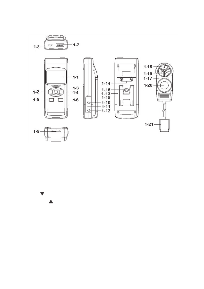
1. The HHEM-SD1 controls and indicators and other physical features
Fig. 1
FRONT
TOP
RIGHT
SIDE
BOTTOM
1-1 Liquid-crystal display
1-2 POWER/ESC button
1-3 FUNC./HOLD/NEXT button
1-4 REC/ENTER button
1-5 SET button
1-6 LOGGER
button
1-7 Socket for multi-function probe or
optional sound level probe
1-8 Socket for Type K or J
thermocouple thermometer
1-9 SD card socket
1-10 RS-232 output jack
BACK
1-11 RESET button
1-12 Socket for 9VDC AC adapter
1-13 Battery compartment cover
1-14 Battery compartment cover
screws
1-15 Kickstand
1-16 Tripod attachment nut
1-17 Multi-function probe head
1-18 Anemometer
1-19 Temperature-humidity sensor
1-20 Lig
1-2
ht sensor
1 Multi-function probe plug
5
Page 7

SETUP
1. Choose the power source. Before using the HHEM-SD1, make sure it is powered
by fresh batteries or an optional 9VDC AC adapter plugged into the bottom jack on
its right side (callout 1-12).
To remove the battery compartment cover (callout 1-13), remove the two screws
holding it in place (callout 1-14). Then install six “AA” batteries in the correct
orientation, using the polarity marks on the inside of t
lace the cover by replacing the two screws.
Rep
he compartment as a guide.
2. Install an SD card. To prepare for setup, also install the supplied 2 GB SD memory
card or another card with a capacity from 1 GB to 16 GB in the socket on the
bottom of the meter (callout 1-9). When installing the card, make sure its gold
contacts are facing front and push the card into the socket until you hear a click.
ove the card, push it in until you hear a click and the card pops out.
To rem
No
w power on the instrument by pressing the POWER/ESC button (callout 1-2) to
generate a short beep. (To power off the HHEM-SD1, press the POWER/ESC button
and hold it until the instrument responds with a long beep.)
When the meter powers on, a series of transient startup screens will briefly appear.
Once the display has stabilized, perform
ented.
pres
3. Set the date and time. Press the SET
the following eight setup steps in the order
button (callout 1-5) and hold it for at
least five seconds, until the word “dAtE” appears in the center of the display, along
with the flashing value “00.00.00” at the lower left, above “yy.mm.dd”.
Set the current year by pressing the SET
or LOGGER button repeatedly until the
correct value appears above “yy”. Quickly (within three seconds), press the
REC/ENTER button to store the setting. The next screen that appears will have the
value above “mm” flashing. Use the SET
or LOGGER button to navigate to the
current month and press the REC/ENTER button to store the setting. When the next
screen flashes the value above “dd”, again use the SET
or LOGGER button to
navigate to the current day and press the REC/ENTER button to store the setting.
(If you press buttons too slowly in setup mode, the screen will revert to the normal
display. To return to the setup sequence, press and hold the SET
button again. To
move ahead to the next field in the sequence or to the next parameter, press the
FUNC./HOLD/NEXT button.)
Once you have set the date, the display will prompt you to set the hour,
minute and second of the current time. Again use the SET
or LOGGER
buttons to navigate to the correct values, and the REC/ENTER button to store
the settings.
6
Page 8

4. Choose a decimal point or comma to represent the decimal division between
integers and fractions (for example, American-style 20.88 vs. European-style
20,88). Once you have set the date and time, the display will show the word
“bASIC” above the phrase “dEC”. Press the SET
button to make “bASIC”
(American style) or “Euro” appear in the upper display, as desired. Press the
REC/ENTER button to store the selection as the default.
5. Enable or disable auto power off. Once the format of decimal point divisions
has been set and stored, the display will show the word “yES’ over the term
“PoFF”. Press the SET
button until the desired automatic power off
management scheme (“yES” for enable; “no” for disable) is displayed. Press the
REC/ENTER button to store the selection. If enabled, the power off function shuts
off the HHEM-SD1 after a period of inactivity of ten minutes.
6. Enable or disable the beeper. Once the auto power off function has been
enabled or disabled, the display will show the word “yES” over the wor
Press
the SET
button until the desired setting (“yES” or “no”) is displayed,
d “bEEP”.
and then press the REC/ENTER button to store the selection as the default.
7. Select the thermocouple type. Once the beeper has been enabled or disabled,
the lower part of the display will show the term “tYPE”. Press the SET
LOGGER
button until your thermocouple’s type (K or J) appears on the display.
or
Then press the REC/ENTER button to store the selection.
8. Select the temperature unit. Once the thermocouple type has been selected
and stored, the lower part of the display will show the term “t-CF”. Press the SET
or LOGGER button until the unit you prefer (“F” for Fahrenheit or “C” for
Celsius”) is displayed. Then press the REC/ENTER button to store the selection
as the default.
9. Set the datalogging sampling time. Once the default temperature unit has been
selected and stored, the display will show a value above the letters “SP-t”. Press
the SET
or LOGGER button to decrease or increase the value until the
desired sampling time appears above “SP-t”. The options are 0, 1, 2, 5, 10, 30,
60, 120, 300, 600, 1800 and 3600 seconds (0 seconds to 1 hour).
10. Format the SD card. Once the sampling time has been set and stored, the term
“Sd-F” will appear in the lower half of the display. Press the REC/ENTER button.
Pressing the REC/ENTER button causes the word “no” or “yES” to appear over the
term “Sd
-F”. Press the
button to make a selection. Choose “yES” whenever a
new SD card is being used, or when a used card is being repurposed (from use
with another SD card instrument or a camera, for example) and all data on it is
to be erased. Choose “no” to preserve any data on a card previously used with
this instrument.
7
Page 9

If you choose “yES”, after you press the REC/ENTER button the instrument will
prompt you to confirm that decision by displaying the term “Ent” below “yES” and
sounding three beeps. To confirm that you want to begin the erasure/formatting
procedure, press the REC/ENTER button. “Ent” will then flash several times and the
instrument will sound another three beeps to confirm that the SD card has been
erased and formatted.
ce the SD card has been set up, the display will then either return to the first of the
On
eight steps in the setup sequence—setting the current date and time—or show the
term “ESC”. If “ESC” appears, press the POWER/ESC button to exit the setup
procedure and enter normal operating mode.
NORMAL OPERATION
1. To prepare to make measurements, power on the HHEM-SD1 and make sure
an SD card is firmly s
Th
e meter can make and display five kinds of measurements:
eated in the socket on the bottom of the meter.
• Air speed and temperature (simultaneously)
• Air temperature and humidity (simultaneously)
• Surface temperature, as measured by an optional Type K or Type J
thermocouple
• Light level
• Sound level (using an optional sound level probe and plug adapter)
2. To select the measurement mode, use the FUN
utton repeatedly cycles through the four main modes (sound level is
the b
C./HOLD/NEXT button. Pressing
measured in a separate operating mode, as explained below). When the
FUNC./HOLD/NEXT button is released, the selected mode becomes the default until
the button is pressed again.
By default, the HHEM-SD1 uses Celsius units for temperature measurements. If you
wish to make Fahrenheit units the default, press the SET
button to enter the setup
procedure and perform Step 8.
3. To measure air speed and temperature simultaneously, seat the multi-function
probe plug (callout 1-21 of Fig. 1) in its socket (callout 1-7) on the top of the meter.
Then press the FUNC./HOLD/NEXT button until the display shows the term “An”.
Holding the probe by its handle, turn its head so the anemometer vanes face the flow
of air. The upper pa
rt of the display will show the air speed while the lower part will
show the temperature (as “ºF” or “ºC”).
To change the units of air speed, use the REC/ENTER button (which has the word
“Unit” stenciled below it). Repeated presses of the button cycle through the five options
for air speed units: m/s (meters/second), fpm (feet per minute), km/h (kilometers/hr),
knots (nautical miles per hour), and mph (
button when the unit you wish to use app
8
miles per hour). Release the REC/ENTER
ears, making it the default until changed.
Page 10

4. To measure air temperature and humidity simultaneously, seat the multi-
function probe plug in its socket on the top of the meter. Then press the
FUNC./HOLD/NEXT button until the display shows the term “rH”. Holding the probe
by its handle, expose its head to a representative volume of air whose temperature
and humidity you wish to measure. The upper part of the display will show the
measured relative humidity value (as “%RH”) while the lower part will show the
tempera
ture (as “ºF” or “ºC”).
5. To measure surface temperature with a thermocouple, make sure the multi-
function probe is not in its socket. Plug an optional Type K or Type J thermocouple
into its dedicated socket (callout 1-8 of Fig. 1). Then press the FUNC./HOLD/NEXT
button until the display shows the term “tP”.
Touch the wire end of the
to measu
re. The display will show its temperature (as “ºF” or “ºC”).
thermocouple to the surface whose temperature you wish
By default, the HHEM-SD1 is configured for a Type K thermocouple. To use a Type J
thermocouple, press the SET
button to enter the setup procedure and perform
Step 7.
6. To measure the ambient light level or the intensity of a light source, seat the
multi-function probe plug in its socket on the top of the meter. Then press the
FUNC./HOLD/NEXT button until the display shows the term “LIgHt”. Completely
cover the light sensor (callout 1-20 of Fig. 1) with your hand. If the display shows
a value other than zero, p
ress the LOGGER
button and hold it for at least three
seconds until you hear a beep and the display shows a zero reading. Then uncover
the light sensor.
Holding the probe by its handle, either expose its head to ambient light or point it at
the light source whose intensity you wish to measure. The display will show the
measured light intensity in units of lux or foot-candles (ft-cd).
To change the unit of light intens
utton toggle through the two options for light intensity units: lux or ft-cd.
the b
ity, use the REC/ENTER button. Repeated presses of
Release the REC/ENTER when the unit you wish to use appears, making it the default
until changed.
7. To measure sound intensity using an optional sound level probe and plug
adapter, first power off the HHEM-SD1. Then plug one end of the plug adapter into
the probe and the other end into the socket at the top of the meter (callout 1-7 of
Fig. 1). Power on both the sound level probe and the HHEM-SD1. The meter’s
display will briefly show the word “Sound” and then switch to a normal
measurement display. Point the head of the sound level probe at the sound source
whose volume you wish to measure. The display will show the sound level, in units
of dB.
Whenever the meter is in measurement mode
is
on by default) by briefly pressing (but not holding) the POWER/ESC button. To
, you can turn off the backlight (which
reactivate the backlight, briefly press the button again.
9
Page 11

Whenever the instrument is in measurement mode, you also can check the current
date and time by briefly pressing the SET
button (which has the words “Time
check” stenciled below it). Doing so causes both values to appear briefly at the lower
left of the display.
HOLDING AND STORING MEASUREMENTS
8. To hold a measured value, press the FUNC./HOLD/NEXT button during the
measurement. Doing so will cause the word “HOLD” to appear at the top of the
display. Pressing the FUNC./HOLD/NEXT button again releases the hold.
9. To record
and recall readings, pres
s the REC/ENTER button while making
measurements. This will make the term “REC” appear at the top of the display.
Pressing the REC/ENTER button again, briefly, will make the term “MAX” appear
to the right of “REC” and switch the display to the maximum value stored in
memory during the last recording session. Pressing the REC/ENTER button again,
briefly, will make the term “MIN” appear to the right of “REC” and switch the
splay to the minimum value stored during the last session.
di
10. To exit recording mode, press the REC/ENTER button and hold it for at least
three seconds, until the term “REC” disappears from the top line of the display.
The display will then revert to showing the current reading.
AUTOMATIC VS. MANUAL DATALOGGING
The HHEM-SD1 can automatically log data at a user-selec
1 s
econd 3,600 seconds (one hour). To view the sampling time that the instrument
has been set up to use, press the LOGGER
button (which has the words “Sampling
ted sampling period from
check” stenciled below it) once. To change the sampling time, perform Step 9 of the
setup procedure.
11. To start automatic datalogging, press the REC/ENTER button once. The top line
of the display will then show the term “REC”. Pressing the LOGGER
button at
this point will make REC flash and add the flashing term “LOGGER” at the top
right of the display. This indicates that the instrument is currently storing
measured values and their time stamps in memory.
12. To pause automatic datalogging, press the LOGGER
button once; this action
makes the flashing term “LOGGER” disappear from the top right of the display
and changes the term “REC” from flashing to constant. Pressing the LOGGER
button again resumes automatic datalogging.
13. To end automatic datalogging, press the REC/ENTER button and hold it for at
least two seconds. This action causes the “REC” message to disappear.
10
Page 12
14. To log data manually, set the sampling time to zero using the procedure detailed
earlier. Then press the REC/ENTER button once. The display will show the term
“REC” on the top line, a value in the middle, and below it the letter “P” on the left
and a number from 1 to 99 on the same line to the right. The number indicates
the position on the SD card that will be used to store manually logged data.
w press the LOGGER
No
button. This will cause the beeper to sound and the term
“LOGGER” to briefly appear at the upper right of the display. As in automatic
datalogging mode, in this mode the instrument is storing measurements and their
time stamps on the SD card.
In manual datalogging mode, however, measurements are being stored continuously
(with a sampling time of zero), and their locations on the card can be changed.
To change the storage location of manually logged data, p
15.
ress the SET
button once; this causes the “P” to disappear from the left side of the display and
the value on its line to begin flashing. Once the flashing begins, you can use the
SET
and LOGGER buttons to change the flashing value to any number
between 1 and 99. Once you have chosen the storage location, press the
REC/ENTER button to save the setting. This causes the value to stop flashing and
the “P” to return.
16. To end manual datalogging, press the REC/ENTER button and hold it for at least
three seconds. This action causes the “REC” message to disappear from the top
line of the display.
TRAN
T
SFERRING DATA FROM THE SD CARD
O A COMPUTER
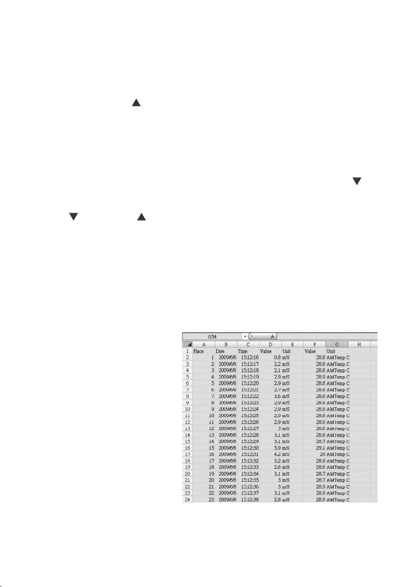
After automatic or manual
datalogging of measurements,
remove the SD card from the
meter and plug it into your
computer either directly (if it has
an SD card slot) or through an
SD card reader.
Because the files containing
time-stamped data logs have
the file extension .xls, they open
in Microsoft’s Excel application.
Figures 2 and 3 show two kinds
of Excel presentations: a data-
ly screen and a graphics-only
on
screen.
Fig. 2. Typical Excel data-only screen
11
Page 13
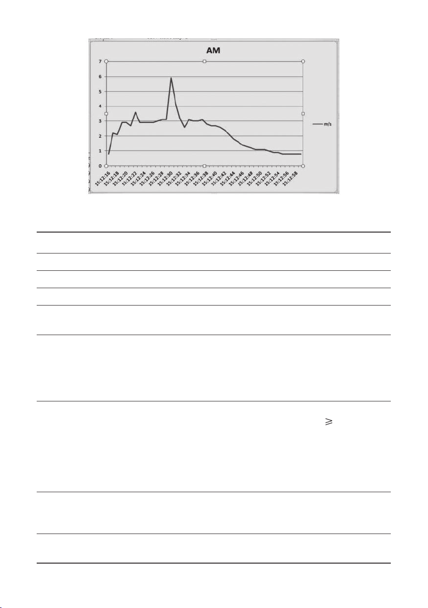
Fig. 3. Typical Excel graphics-only screen
SPECIFICATIONS
Embedded microcontroller Custom one-chip LSI device
Display type Liquid-crystal with green backlight
Display size 2.05 x 1.5 in. (52 x 38mm)
Parameters measured Air temperature, relative humidity (R.H.),
air speed, light level
Measurement range For temperature, 32 to 122ºF (0 to 50ºC); for R.H.,
0 to 95%; for air speed: 0.4 to 25 m/sec,
1.4 to 90 km/hr, 0.9 to 55.9 mph, 0.8 to
48.6 knots, 80 to 4930 ft/min; for light level:
0 to 20,000 lux, 0 to 1860 ft-cd
Measurement accuracy For temperature: ± 1.5ºF (± 0.8ºC); for humidity:
± (3% of reading + 1%) for R.H. values
± 3% of reading for R.H values <70%; for air speed:
± (2% + 0.2 m/sec), ± (2% + 0.8 km/hr),
± (2% + 0.4 mph), ± (2% + 0.4 knots),
± (2% + 40 ft/min); for light level,
± (5% of reading ± 8 digits)
Measurement resolution For temperature, 0.1ºF or °C; for humidity, 0.1% of
reading; for air speed: 0.1 ms, 0.1 km/hr, 0.1 mph,
0.1 knots, 1.0 ft/min; for light level: 1 lux, 0.1 ft-cd
Sampling time options 0, 1, 2, 5, 10, 30, 60, 120, 300, 600, 1800 or
3600 seconds (0 seconds to 1 hour)
70%;
12
Page 14

Settable parameters Date, time, auto power off, beep sound, sampling time,
decimal point or comma decimal division, temperature
unit, air speed unit, light level unit, optional thermocouple type (K or J)
Storable/recallable readings Maximum, minimum
SD card capacity 1 GB to 16 GB
Operating temperature 32° to 122ºF (0° to 50ºC)
Operating relative humidity 0 to 85%
Power source 6 Alkaline “AA” batteries or optional 9-VDC AC adapter
Power consumption 3.5 mADC (normal operation, with backlight off and
SD card not saving data); 28 mADC with backlight on
and card saving data; 40 mADC with backlight on and
card saving data
Dimensions of meter 5.31 x 2.36 x 1.30 in. (135 x 60 x 33mm)
Weight of meter 1.13 lb. (515g) Dimensions of probe
4.13 x 1.81 x 1.14 in. (105 x 46 x 29mm)
MAINTENANCE & TROUBLESHOOTING TIPS
Keep the multi-function probe clean. Store it in the carrying case when you are not
using the meter.
When the icon appears in the left corner of the display, it’s time to replace the
six “AA” batteries that power the instrument (although measure ments will remain
valid for several hours after the low-battery indicator first appears). Replacing the
batteries r
i
n place, as explained earlier. After inserting fresh batteries in the correct orientation,
tighten the screws to secure the cover.
If the meter “freezes” (like a computer) and buttons become unresponsive,
try resetting the instrument by pushing the RESET button on its right side
(callout 1-11 of Fig. 1) with the end of a paper clip.
Remove th
Do not drop or disassemble the meter or immerse it in water.
equires removing the two screws that hold the battery compartment cover
e batteries when storing the meter for an extended period of time.
13
Page 15

OPTIONAL ACCESSORIES
Optional accessories available from Omega include:
• Sound level probe and plug adapter
• Type K and Type J thermocouples
• 9VDC adapter for a 110V power supply
14
Page 16

NOTES
______________________________________________________________
______________________________________________________________
______________________________________________________________
______________________________________________________________
______________________________________________________________
______________________________________________________________
______________________________________________________________
______________________________________________________________
______________________________________________________________
______________________________________________________________
______________________________________________________________
______________________________________________________________
______________________________________________________________
______________________________________________________________
______________________________________________________________
______________________________________________________________
______________________________________________________________
______________________________________________________________
______________________________________________________________
15
Page 17

WARRANTY/DISCLAIMER
OMEGA ENGINEERING, INC. warrants this unit to be free of defects in materials and workmanship
for a period of 13 months from date of purchase. OMEGA’s WARRANTY adds an additional one (1)
month grace period to the normal one (1) year product warranty to cover handling and shipping
time. This ensures that OMEGA’s customers receive maximum coverage on each product.
If the unit malfunctions, it must be returned to the factory for evaluation. OMEGA’s Customer
Service Department will issue an Authorized Return (AR) number immediately upon phone or
written request. Upon examination by OMEGA, if the unit is found to be defective, it will be repaired
or replaced at no charge. OMEGA’s WARRANTY does not apply to defects resulting from any action
of the purchaser, including but not limited to mishandling, improper interfacing, operation outside
of design limits, improper repair, or unauthorized modification. This WARRANTY is VOID if the unit
shows evidence of having been tampered with or shows evidence of having been damaged as a
result of excessive corrosion; or current, heat, moisture or vibration; improper specification;
misapplication; misuse or other operating conditions outside of OMEGA’s control. Components in
which wear is not warranted, include but are not limited to contact points, fuses, and triacs.
OMEGA is pleased to offer suggestions on the use of its various products. However,
OMEGA neither assumes responsibility for any omissions or errors nor assumes liability
for any damages that result from the use of its products in accordance with
information provided by OMEGA, either verbal or written. OMEGA warrants only that
the parts manufactured by the company will be as specified and free of defects.
OMEGA MAKES NO OTHER WARRANTIES OR REPRESENTATIONS OF ANY KIND
WHATSOEVER, EXPRESSED OR IMPLIED, EXCEPT THAT OF TITLE, AND ALL IMPLIED
WARRANTIES INCLUDING ANY WARRANTY OF MERCHANTABILITY AND FITNESS FOR
A PARTICULAR PURPOSE ARE HEREBY DISCLAIMED. LIMITATION OF LIABILITY: The
remedies of purchaser set forth herein are exclusive, and the total liability of OMEGA
with respect to this order, whether based on contract, warranty, negligence,
indemnification, strict liability or otherwise, shall not exceed the purchase price of the
component upon which liability is based. In no event shall OMEGA be liable for
consequential, incidental or special damages.
CONDITIONS: Equipment sold by OMEGA is not intended to be used, nor shall it be used: (1) as a
“Basic Component” under 10 CFR 21 (NRC), used in or with any nuclear installation or activity; or
(2) in medical applications or used on humans. Should any Product(s) be used in or with any
nuclear installation or activity, medical application, used on humans, or misused in any way,
OMEGA assumes no responsibility as set forth in our basic WARRANTY / DISCLAIMER language,
and, additionally, purchaser will indemnify OMEGA and hold OMEGA harmless from any liability
or damage whatsoever arising out of the use of the Product(s) in such a manner.
RETURN REQUESTS/INQUIRIES
Direct all warranty and repair requests/inquiries to the OMEGA Customer Service Department.
BEFORE RETURNING ANY PRODUCT(S) TO OMEGA, PURCHASER MUST OBTAIN AN
AUTHORIZED RETURN (AR) NUMBER FROM OMEGA’S CUSTOMER SERVICE DEPARTMENT (IN
ORDER TO AVOID PROCESSING DELAYS). The assigned AR number should then be marked on the
outside of the return package and on any correspondence.
The purchaser is responsible for shipping charges, freight, insurance and proper packaging to
prevent breakage in transit.
FOR WARRANTY
RETURNS, please have the
following information available BEFORE
contacting OMEGA:
1. Purchase Order number under which
the product was PURCHASED,
2. Model and serial number of the product
under warranty, and
3. Repair instructions and/or specific
problems relative to the product.
FOR NON-WARRANTY REPAIRS,
consult OMEGA
for current repair charges. Have the following
information available BEFORE contacting OMEGA:
1. Purchase Order number to cover the
COST of the repair,
2. Model and serial number of the
product, and
3. Repair instructions and/or specific problems
relative to the product.
OMEGA’s policy is to make running changes, not model changes, whenever an improvement is possible.
This affords our customers the latest in technology and engineering.
OMEGA is a registered trademark of OMEGA ENGINEERING, INC.
© Copyright 2012 OMEGA ENGINEERING, INC. All rights reserved. This document may not be copied, photocopied, repro-
duced, translated, or reduced to any electronic medium or machine-readable form, in whole or in part, without the prior
written consent of OMEGA ENGINEERING, INC.
Page 18

Where Do I Find Everything I Need for
Process Measurement and Control?
OMEGA…Of Course!
Shop online at omega.com
SM
TEMPERATURE
䡺⻬
Thermocouple, RTD & Thermistor Probes, Connectors, Panels & Assemblies
䡺⻬
Wire: Thermocouple, RTD & Thermistor
䡺⻬
Calibrators & Ice Point References
䡺⻬
Recorders, Controllers & Process Monitors
䡺⻬
Infrared Pyrometers
PRESSURE, STRAIN AND FORCE
䡺⻬
Transducers & Strain Gages
䡺⻬
Load Cells & Pressure Gages
䡺⻬
Displacement Transducers
䡺⻬
Instrumentation & Accessories
FLOW/LEVEL
䡺⻬
Rotameters, Gas Mass Flowmeters & Flow Computers
䡺⻬
Air Velocity Indicators
䡺⻬
Turbine/Paddlewheel Systems
䡺⻬
Totalizers & Batch Controllers
pH/CONDUCTIVITY
䡺⻬
pH Electrodes, Testers & Accessories
䡺⻬
Benchtop/Laboratory Meters
䡺⻬
Controllers, Calibrators, Simulators & Pumps
䡺⻬
Industrial pH & Conductivity Equipment
DATA ACQUISITION
䡺⻬
Data Acquisition & Engineering Software
䡺⻬
Communications-Based Acquisition Systems
䡺⻬
Plug-in Cards for Apple, IBM & Compatibles
䡺⻬
Data Logging Systems
䡺⻬
Recorders, Printers & Plotters
HEATERS
䡺⻬
Heating Cable
䡺⻬
Cartridge & Strip Heaters
䡺⻬
Immersion & Band Heaters
䡺⻬
Flexible Heaters
䡺⻬
Laboratory Heaters
ENVIRONMENTAL
MONITORING AND CONTROL
䡺⻬
Metering & Control Instrumentation
䡺⻬
Refractometers
䡺⻬
Pumps & Tubing
䡺⻬
Air, Soil & Water Monitors
䡺⻬
Industrial Water & Wastewater Treatment
䡺⻬
pH, Conductivity & Dissolved Oxygen Instruments
M5078/0212
 Loading...