

Page 1
omega.com
e-mail: [email protected]
For latest product manuals:
omegamanual.info
HHB200/300
Video Inspection System
Shop online at
User’s Guide
MADE IN TAIWAN
Page 2

OMEGAnet®On-Line Service Internet e-mail
omega.com [email protected]
It is the policy of OMEGA Engineering, Inc. to comply with all worldwide safety and EMC/EMI regulations that apply. OMEGA
is constantly pursuing certification of its products to the European New Approach Directives. OMEGA will add the CE mark
to every appropriate device upon certification.
The information contained in this document is believed to be correct, but OMEGA accepts no liability for any errors it
contains, and reserves the right to alter specifications without notice.
WARNING: These products are not designed for use in, and should not be used for, human applications.
Benelux:
Managed by the United Kingdom Office
Toll-Free: 0800 099 3344 TEL: +31 20 347 21 21
FAX: +31 20 643 46 4 e-mail: [email protected]
Czech Republic:
Frystatska 184
733 01 Karviná, Czech Republic
Toll-Free: 0800-1-66342 TEL: +420-59-6311899
FAX: +420-59-6311114 e-mail: [email protected]
France:
Managed by the United Kingdom Office
Toll-Free: 0800 466 342 TEL: +33 (0) 161 37 29 00
FAX: +33 (0) 130 57 54 27 e-mail: [email protected]
Germany/Austria:
Daimlerstrasse 26
D-75392 Deckenpfronn, Germany
Toll-Free: 0800 6397678 TEL: +49 (0) 7056 9398-0
FAX: +49 (0) 7056 9398-29 e-mail: [email protected]
Servicing Europe:
U.S.A. and Canada:
Sales Service: 1-800-826-6342/1-800-TC-OMEGA
®
Customer Service: 1-800-622-2378/1-800-622-BEST
®
Engineering Service: 1-800-872-9436/1-800-USA-WHEN
®
U.S.A.: ISO 9001 Certified
OMEGA Engineering, Inc.,
One Omega Drive, P.O. Box 4047
Stamford, CT 06907-0047
Toll-Free: 1-800-826-6342 Tel: (203) 359-1660
FAX: (203) 359-7700 e-mail: [email protected]
Servicing North America:
For immediate technical or application assistance:
Mexico/Latin America:
En Español: 001 (203) 359-7803
FAX: 001 (203) 359-7807
[email protected]
e-mail: [email protected]
United Kingdom:
ISO 9001 Certified
OMEGA Engineering Ltd.
One Omega Drive
River Bend Technology Centre
Northbank
Irlam, Manchester M44 5BD
United Kingdom
Toll-Free: 0800-488-488
TEL: +44 (0) 161 777-6611
FAX: +44 (0) 161 777-6622
e-mail: [email protected]
Canada:
976 Bergar
Laval (Quebec), H7L 5A1 Canada
Toll-Free: 1-800-826-6342 TEL: (514) 856-6928
FAX: (514) 856-6886 e-mail: [email protected]
Page 3

CONTENTS
Introduction . . . . . . . . . . . . . . . . . . . . . . . . . . . . . . . . . . . . 1
Features . . . . . . . . . . . . . . . . . . . . . . . . . . . . . . . . . . . . . . . 1
Safety Instructions . . . . . . . . . . . . . . . . . . . . . . . . . . . . . 2
Product Components . . . . . . . . . . . . . . . . . . . . . . . . . . . 3
Installation . . . . . . . . . . . . . . . . . . . . . . . . . . . . . . . . . . . . . 4
Battery Installation . . . . . . . . . . . . . . . . . . . . . . . . . . . . . . . . . . 4
Battery Precautions . . . . . . . . . . . . . . . . . . . . . . . . . . . . . . . . . . 4
Connecting the Display Unit to the Camera Head and Pro
Accessories Installation . . . . . . . . . . . . . . . . . . . . . . . . . . . . . . 5
Operation Instructions . . . . . . . . . . . . . . . . . . . . . . . . . . 6
Basic Operation . . . . . . . . . . . . . . . . . . . . . . . . . . . . . . . . . . . . . 6
Operation Precautions . . . . . . . . . . . . . . . . . . . . . . . . . . . . . . 6-8
Maintenance Instructions . . . . . . . . . . . . . . . . . . . . . . . . . . . 8-9
Trouble Shooting . . . . . . . . . . . . . . . . . . . . . . . . . . . . . . . . . . . . 9
Specifications . . . . . . . . . . . . . . . . . . . . . . . . . . . . . . . . . 10
Cautions . . . . . . . . . . . . . . . . . . . . . . . . . . . . . . . . . . . . . . 11
be 5
i
Page 4

INTRODUCTION
The HHB200 and The HHB300 inspection systems have
been designed as a user friendly and economical way of solving
hidden problems and increasing productivity. The product has
a high clarity color LCD to show clear images. The camera head
is housed inside the tip of the probe with adjustable LED lights,
which helps you to reach into gaps and holes. The mirror tip
is included to make it possible to view different angles. The
magnetic tip is used to pick up small metal objects. The
is used to grab onto objects.
The video inspection systems have the advantages of clear
images, easy operation and portability. It is widely used in
applications such as HVAC/R building, aviation and vehicles
maintenance.
hook
FEATURES
• HHB200: 2.4" (70mm) Color LCD Screen
for crystal clear image
• HHB300: 3.5" (88.9mm) Color LCD Screen
for superb clarity and viewing effect
• 0.47" (12mm) diameter Camera-tipped Probe is flexible
and strong with built-in adjustable LED lighting, and is
slim enough to perform automotive engine check-up
• Flexible Probe retains configured shape to suit
different inspection needs
• View findings instantaneously
• Mirror, Magnet and Pick-up Hook
1
Page 5

SAFETY INSTRUCTIONS
Failure to follow the instructions listed below may result in
electric shock or personal injury.
• Read and understand all instructions prior to any operation.
• Do not remove any labels from the product.
dark areas may cause accidents.
• Do not operate the product in the presence of
flammable/explosive gases.
• Do not use the product around corrosive chemicals
which can ruin the picture quality.
• Keep bystanders, children and visitors away
while oper
• Stay alert, watch what you are doing and use common
sense. A moment of interruption can result in serious
personal injury.
• Do not over-reach. Keep proper footing and balance
at all times.
• Always wear eye protective gear. Dust mask, non-skid
safety shoes, hard hat or hearing protection must be used
for appropriate conditions.
• Do not place the product on any unstable cart or surface.
The product may fall causing serious injury to a person or
serious dama
• Never spill liquid of any kind on the video display units.
Liquid increases the risk of electrical shock and damage
to the product.
• Do not use the device for personal or medical use.
• The units are not shock-resistant. Do not drop it.
ating the product.
ge to the product.
2
Page 6
PRODUCT COMPONENTS
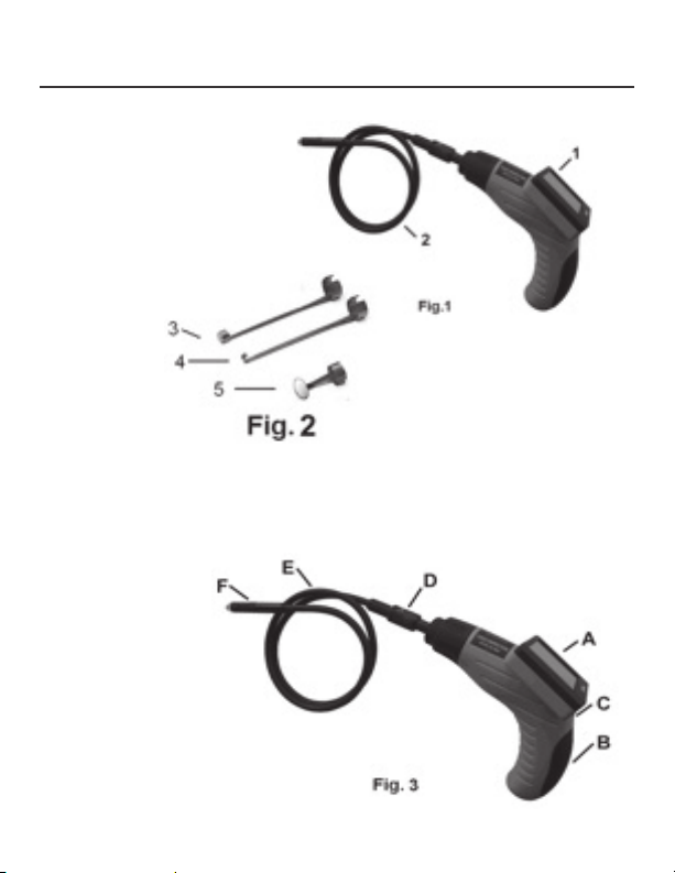
1. Hand Held Display Unit
2. Camera Head and Probe
3. Magnetic Tip
4. Hook Tip
5. Mirror Tip
A. LCD Screen
B. Battery Compartment
C.Switch / LED Lighting Adjusting Button
D.Probe Connector
E. Probe
F. Camera Head
3
Page 7
INSTALLATION
BATTERY INSTALLATION:
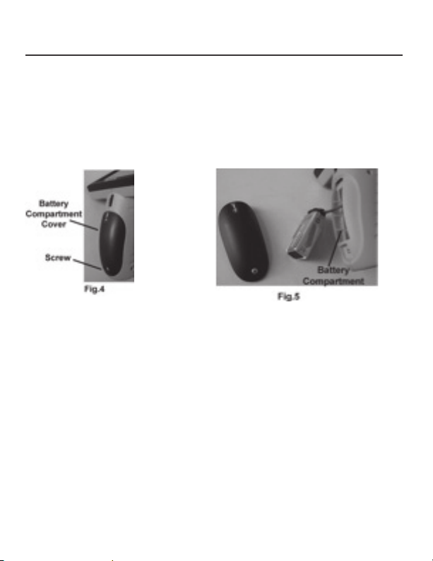
1. Use a screwdriver to open the screw on the battery
compartment cover (See Fig. 4).
2. Insert one “9V” alkaline battery (MN1604 ) into the battery
compartment. Close the battery cover and fasten
the screw (See Fig. 5).
BATTERY PRECAUTIONS!
• Remove the battery while cleaning the unit.
• Remove the battery before storing the unit for
a long period of time.
• Be sure to install the battery with the correct polarity
as indicated in the battery compa
• Properly dispose of the batteries. Exposure to high
temperatures can cause the batteries to explode.
Do not dispose in fire. Place tape over the terminals
to prevent direct contact with other objects. Some
countries have regulations concerning battery disposal.
Please follow all applicable regulations.
rtment.
4
Page 8
CONNECTING THE DISPLAY UNIT TO THE CAMERA
HEAD AND PROBE:
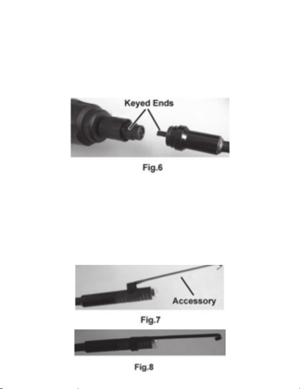
The display unit must be connected to the cameral head and
probe. To connect the probe to the display unit, make sure the
keyed ends are properly aligned (See Fig. 6). Once they are
aligned, tighten the nut.
ACCESSORIES INSTALLATION:
The three accessories include mirror tip, hook tip and
magnetic tip (See Fig. 2). All are attached to the camera
head the same way. Hold the camera head as shown in Fig. 7,
slip the semicircle
camera head and then rotate the accessory 90° to fix
as shown in Fig. 8.
end of the accessory over the flats of the
5
Page 9
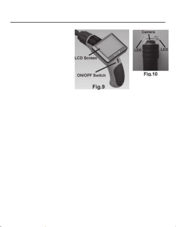
OPERATION INSTRUCTIONS
BASIC OPERATION:
To turn the unit on, hold
the LCD display unit
facing you (See Fig. 9).
Roll the switch towards
you to turn the power
on. The switch then acts
as a dimmer for the twin
LED’s (See Fig.10), which
is the power supply for
the camera.
This product is designed for hard-to-reach distance inspection.
Typical applications include HVAC/R inspections, car inspections, circuitry, vessel, and aircraft. While in operation, the
product is easy to
to pick up items such as rings or screws on the floor.
OPERATION PRECAUTIONS!
1. Please read all the safety instructions carefully.
2. The probe is flexible to help you operate in hard-to-reach
areas. Please don’t insert or bend by force. Please do not
over bend any part of the probe. Normally, the bending
radius should not be less than 2" (50mm) to prevent from
causing permanent damage to the probe.
3. Don’t use the probe or camera head to
surroundings, clear pathways or clogged areas.
4. The hand-held display unit is not waterproof. The camera
head and its cover is waterproof, but not acid-proof or
fireproof. Do not touch these materials or they will ruin
the camera head’s protective plastic. Avoid submersing
extend ahead. The accessories can be used
modify
6
Page 10

the camera head into corrosive, oily places or high
temperature objects.
5. Don’t place the cameral head or probe into anything or
anywhere that may contain a live electrical charge.
Please check following methods to avoid injury.
For walls: For inspecting the inside walls, be sure to shut off
the circuit breaker to the whole house before
using the tool.
For pipes: If you suspect a metal pipe could contain an
electrical charge, have a qualified electrician
to check the pipe b
in some cases, can be returned to the cast
aluminum pipes and cause them to be charged.
For automobiles: Be sure the automobile is not running during
inspection. Metal and liquid under the hood may
be hot. Don’t get oil or gas on the camera head.
• Please do not operate this product unless the manual
has been read thoroughly and proper training has been
completed.
• Do not immerse the handheld display unit in water which
will result in electric shock a
• The camera head is water-proof, but the handheld display
is not water-proof.
• Do not use the product if condensation forms inside
the camera head.
• If the tool does not work well after turning it on. Please
take the batteries out and do not use. Please have the
unit checked by a qualified technician.
• Store idle products out of reach of children and other
untrained personnel. The product is dangerous in the
hands of untrained users.
• Maintain the inspection produ
efore using. A ground circuit,
nd damages.
ct with care. If the product
7
Page 11

is dropped, check for the breakage which may affect it’s
operation. If it is damaged, have the product serviced
before using. Many accidents are caused by poorly
maintained products.
• Use only accessories that are recommended by the
manufacturer for your product. Accessories are suitable
for the product, but may become hazardous when used
on another product.
• Dry your hands before turning the product ON or OFF
and before replacing battery.
• Protect against excessive h
kept away from heat sources, such as radiators, heat
registers, stoves or other products (including amplifiers)
that produce heat. Do not use the product near moving
machinery or areas where the temperature exceeds
113°F (45ºC).
• Store the product in ventilated and dry places.
eat. The product should be
MAINTENANCE INSTRUCTIONS
• Product service must be performed only by qualified
repair personnel. Services performed by untrained
repair personnel could result in injury.
• When servicing the product, only use identical replacement
parts. Use of unauthorized parts or failure to follow
maintenance instructions may create a risk of electrical
shock or injury.
• Don’t attempt to take any pieces of this product apart
unless directed by this manual.
• Provide proper cleani
product. Use soap or soft cloth to clean. Gently clean the
LCD with a dry cloth. Remove the battery before cleaning.
ng. Don’t use acetones to clean the
8
Page 12

• Upon completion of any service or repair, please ask the
service technician to check if the product is in proper
working condition.
Stop using the unit if it starts smoking or emitting noxious fumes.
•
• Remove the battery and ask a qualified personnel under
the following conditions:
A. If liquid has been spilled or objects have fallen
into the product.
B. If product doesn’t operate normally even if you have
followed the operation instructions.
C. If the product has been drop
any way.
D. When the product exhibits a distinct change
in performance.
ped or damaged in
TROUBLE SHOOTING
Symptoms Reasons Solutions
The connection Check connection
The connection is loose. and try again.
Display is on, Image head Check if it is covered
but no image. covered by by debris.
debris.
LED’s on the camera
head are dim at max
bright, display
changes from Low battery. Replace battery.
black to white,
color display
turns itself off
after a period.
The product Dead batteries. Replace battery.
won’t turn on.
9
Page 13
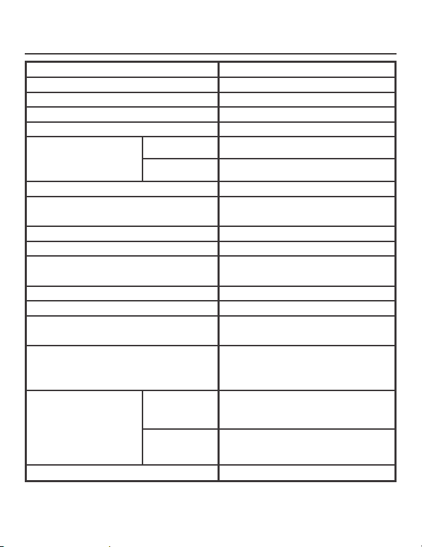
SPECIFICATIONS
Video Inspection Specifications
Recommended use Indoor
Viewable Angle 60°
Viewable Distance .98" to 11.8" (2.5 to 30cm)
Diameter of Camera Head .47" (12mm)
HHB200
Image Display
HHB300
Resolution 320 x 234 pixels
Accessories Mirror tip, Hook tip
Probe Length 39.4" (100cm)
Light Source Adjustable LED
Power Source One “9V” alkaline battery
Estimated Battery Life About one hour
Operating Temperature 32° to 113° F (0° to 45°C)
Operating Humidity 5%〜95%Rh
Storage Temperature -4° to 140°F
HHB200
Body Dimensions
HHB300
Weight About 17.6oz (0.5 kg)
2.4" T T/LCD
3.5" TFT/LCD
and Magnetic tip
(MN1604)
non-condensing
(-20° to 60°C)
≤85% (w/o battery)
8.5" x 4.6" x 3.2"
(215 x 156 x 80mm)
8.5" x 4.6" x 3.8"
(215 x 156 x 96mm)
10
Page 14

CAUTIONS!
• Don’t drop the product or use by force.
• Don’t disassemble the product to avoid failure.
• Don’t place the product with corrosive gas or objects.
• Don’t expose the product in environment which is
with shock, too high or too low temperatures.
• Store the product in a safe area.
• Don’t immerse the product into water which can cause
damages to the product.
• Please take out the battery if not in use for long period
of time.
11
Page 15

FOR WARRANTY RETURNS, please have the
following information available BEFORE contacting
OMEGA:
1. Purchase Order number under which the
product was PURCHASED,
2. Model and serial number of the product under
warranty, and
3. Repair instructions and/or specific problems
relative to the product.
FOR NON-WARRANTY REPAIRS,
consult OMEGA
for current repair charges. Have the following
information available BEFORE contacting OMEGA:
1. Purchase O rde r number to cover the COST
of the repair,
2. Model and serial number of the product, and
3. Repair instructions and/or specific problems
relative to the product.
OMEGA’s policy is to make running changes, not model changes, whenever an improvement is possible. This affords our customers the latest in technology and engineering.
OMEGA is a registered trademark of OMEGA ENGINEERING, INC.
© Copyright 2010 OMEGA ENGINEERING, INC. All rights reserved. This document may not be copied, photocopied, reproduced,
translated, or reduced to any electronic medium or machine-readable form, in whole or in part, without the prior written consent of
OMEGA ENGINEERING, INC.
WARRANTY / DISCLAIMER
OMEGA ENGINEERING, INC. warrants this unit to be free of defects in materials and workmanship for a
period of 13 months from date of purchase. OMEGA’s Warranty adds an additional one (1) month grace
period to the normal one (1) year product warranty to cover handling and shipping time. This
ensures that OMEGA’s customers receive maximum coverage on each product.
If the unit malfunctions, it must be returned to the factory for evaluation. OMEGA’s Customer Service
Department will issue an Authorized Return (AR) number immediately upon phone or written request.
Upon examination by OMEGA, if the unit is found to be defective, it will be repaired or replaced at no
charge. OMEGA’s WARRANTY does not apply to defects resulting from any action of the purchaser,
including but not limited to mishandling, improper interfacing, operation outside of design limits,
improper repair, or unauthorized modification. This WARRANTY is VOID if the unit shows evidence of
having been tampered with or shows evidence of having been damaged as a result of excessive corrosion; or current, heat, moisture or vibration; improper specification; misapplication; misuse or other
operating conditions outside of OMEGA’s control. Components in which wear is not warranted, include
but are not limited to contact points, fuses, and triacs.
OMEGA is pleased to offer suggestions on the use of its various products. However, OMEGA
neither assumes responsibility for any omissions or errors nor assumes liability for any
damages that result from the use of its products in accordance with information provided by
OMEGA, either verbal or written. OMEGA warrants only that the parts manufactured by the
company will be as specified and free of defects. OMEGA MAKES NO OTHER WARRANTIES
OR REPRESENTATIONS OF ANY KIND WHATSOEVER, EXPRESSED OR IMPLIED, EXCEPT
THAT OF TITLE, AND ALL IMPLIED WARRANTIES INCLUDING ANY WARRANTY OF
MERCHANTABILITY AND FITNESS FOR A PARTICULAR PURPOSE ARE HEREBY
DISCLAIMED. LIMITATION OF LIABILITY: The remedies of purchaser set forth herein are
exclusive, and the total liability of OMEGA with respect to this order, whether based on
contract, warranty, negligence, indemnification, strict liability or otherwise, shall not
exceed the purchase price of the component upon which liability is based. In no event shall
OMEGA be liable for consequential, incidental or special damages.
CONDITIONS: Equipment sold by OMEGA is not intended to be used, nor shall it be used: (1) as a “Basic
Component” under 10 CFR 21 (NRC), used in or with any nuclear installation or activity; or (2) in medical
applications or used on humans. Should any Product(s) be used in or with any nuclear installation or
activity, medical application, used on humans, or misused in any way, OMEGA assumes no
responsibility as set forth in our basic WARRANTY/ DISCLAIMER language, and, additionally, purchaser
will indemnify OMEGA and hold OMEGA harmless from any liability or damage whatsoever arising out
of the use of the Product(s) in such a manner.
RETURN REQUESTS / INQUIRIES
Direct all warranty and repair requests/inquiries to the OMEGA Customer Service Department. BEFORE
RETURNING ANY PRODUCT(S) TO OMEGA, PURCHASER MUST OBTAIN AN AUTHORIZED RETURN
(AR) NUMBER FROM OMEGA’S CUSTOMER SERVICE DEPARTMENT (IN ORDER TO AVOID PROCESSING DELAYS). The assigned AR number should then be marked on the outside of the return package and
on any correspondence. The purchaser is responsible for shipping charges, freight, insurance and proper packaging to prevent breakage in transit.
Page 16

Where Do I Find Everything I Need for
Process Measurement and Control?
OMEGA…Of Course!
Shop online at omega.com
sm
M4841/0110
TEMPERATURE
䡺⻬
Thermocouple, RTD & Thermistor
Probes, Connectors, Panels &
Assemblies
䡺⻬
Wire: Thermocouple, RTD & Thermistor
䡺⻬
Calibrators & Ice Point References
䡺⻬
Recorders, Controllers & Process
Monitors
䡺⻬
Infrared Pyrometers
PRESSURE, STRAIN AND FORCE
䡺⻬
Transducers & Strain Gages
䡺⻬
Load Cells & Pressure Gages
䡺⻬
Displacement Transducers
䡺⻬
Instrumentation & Accessories
FLOW/LEVEL
䡺⻬
Rotameters, Gas Mass Flowmeters &
Flow Computers
䡺⻬
Air Velocity Indicators
䡺⻬
Turbine/Paddlewheel Systems
䡺⻬
Totalizers & Batch Controllers
pH/CONDUCTIVITY
䡺⻬
pH Electrodes, Testers & Accessories
䡺⻬
Benchtop/Laboratory Meters
䡺⻬
Controllers, Calibrators, Simulators &
Pumps
䡺⻬
Industrial pH & Conductivity
Equipment
DATA ACQUISITION
䡺⻬
Data Acquisition & Engineering
Software
䡺⻬
Communications-Based Acquisition
Systems
䡺⻬
Plug-in Cards for Apple, IBM &
Compatibles
䡺⻬
Data Logging Systems
䡺⻬
Recorders, Printers & Plotters
HEATERS
䡺⻬
Heating Cable
䡺⻬
Cartridge & Strip Heaters
䡺⻬
Immersion & Band Heaters
䡺⻬
Flexible Heaters
䡺⻬
Laboratory Heaters
ENVIRONMENTAL
MONITORING AND CONTROL
䡺⻬
Metering & Control Instrumentation
䡺⻬
Refractometers
䡺⻬
Pumps & Tubing
䡺⻬
Air, Soil & Water Monitors
䡺⻬
Industrial Water & Wastewater
Treatment
䡺⻬
pH, Conductivity & Dissolved Oxygen
Instruments
 Loading...