

Page 1

User’s Guide
Shop online at
omega.com
e-mail: [email protected]
For latest product manuals:
www.omegamanual.info
MADE IN CHINA
®
HH91
Single Channel
and
Two Channel
Digital Thermocouple
Thermometers
HH92
Page 2

omega.com [email protected]
U.S.A.:
Stamford, CT 06907-0047 USA
Servicing North America:
Omega Engineering, Inc., One Omega Drive, P.O. Box 4047
Toll-Free: 1-800-826-6342 (USA & Canada only)
Customer Service: 1-800-622-2378 (USA & Canada only)
Engineering Service: 1-800-872-9436 (USA & Canada only)
Tel: (203) 359-1660 Fax: (203) 359-7700
e-mail: [email protected]
For Other Locations Visit omega.com/worldwide
The information contained in this document is believed to be correct, but OMEGA
accepts no liability for any errors it contains, and reserves the right to alter
specifications without notice.
WARNING: These products are not designed for use in, and should not be used for,
human applications.
Page 3

TABLE OF CONTENTS
Key Features . . . . . . . . . . . . . . . . . . . . . . . . . . 2 – 3
What’s in the Package . . . . . . . . . . . . . . . . . . . . . . 3
Quick Start Guide . . . . . . . . . . . . . . . . . . . . . . . . . . 3
Product Overview . . . . . . . . . . . . . . . . . . . . . . . 3 – 7
Setup Instructions . . . . . . . . . . . . . . . . . . . . . 7 – 11
Install Battery . . . . . . . . . . . . . . . . . . . . . . . . . . 7
Perform Setup Procedure . . . . . . . . . . . . . 7 – 11
Install Thermocouple(s) . . . . . . . . . . . . . . . . . 11
Operating Instructions . . . . . . . . . . . . . . . . . 12 – 13
Monitoring Temperature(s) in Real Time . 12 – 13
Displaying Min/Max/Avg Temperatures . . . . . 13
Specifications . . . . . . . . . . . . . . . . . . . . . . . 13 – 14
Operating & Maintenance Tips . . . . . . . . . . . . . . 14
KEY FEATURES
• Min/Max/Avg memory
• Compatible with “K”, “J”, “T” and “E” type
thermocouples
• Displays difference between thermocouple
readings T1-T2 (HH92 only)
• 2.4 in. diagonal LCD with dual temperature
readouts + relative time clock readout
• Adjustable relative time clock enables resetting
measurement timeline
2
Page 4

• Choice of three temperature units: °C, °F and °K
• Data hold button
• Manual temperature compensation (offset) for
thermocouple(s)
• Adjustable Auto Power Off trigger
• Powered by “9V” battery
WHAT’S IN THE PACKAGE
Both models come in a white box with this user’s
manual. The HH91 includes one “K” type bead
thermocouple probe with a measurement range of 40° to 572°F (-40° to 300°C). The HH92 comes with
two “K” type probes with the same range.
A variety of other “K” type thermocouple probes
with different sensor types, form factors and
temperature ranges are available from OMEGA. Visit
www.omega.com and enter “K type probe” in
the SEARC
H box.
QUICK START GUIDE
1. Obtain and install a “9V” battery.
2. Plug included “K” type thermocouple probe(s) into
the top jack(s).
3. Press the POWER button.
PRODUCT OVERVIEW
Figure 1 shows all of the controls, indicators and
physical features of the HH91 and HH92, including
the differences between their keypads and jack
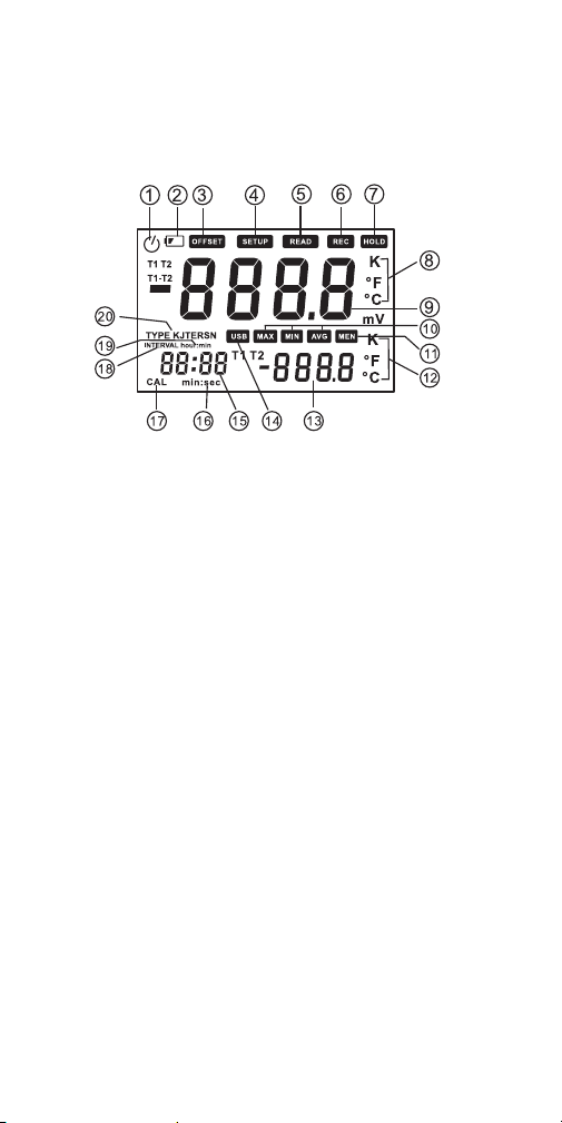
configurations. Figure 2 shows all possible
indications on the LCD. Familiarize yourself with the
positions and functions of all controls, indicators and
physical features before moving on to the Setup
Instructions and Operating Instructions.
3
Page 5
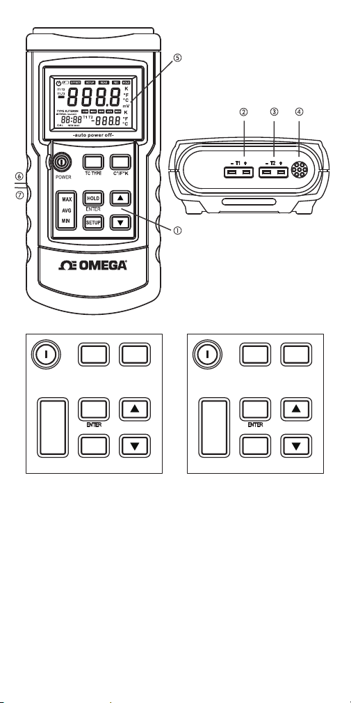
HH91
TOP
Fig. 1. The controls,
display and physical
features of the HH91
and HH92
POWER
MAX
AVG
MIN
TC TYPE
HOLD
ENTER
SETUP
C°/F°K
POWER
T1/T2/T1-T2
MAX
AVG
MIN
C°/F°K
HOLD
ENTER
SETUP
HH91 Keypad HH92 Keypad
1. Keypad
2. T1 jack for spade lug thermocouple
3. T2 jack for spade lug thermocouple (HH92 only)
4. Ambient temperature sensor
5. LCD
6. Flip-up stand (on back)
7. Battery compartment (on back)
4
Page 6

POWER button. Powers thermometer on and off.
TC TYPE button (HH91 only). Selects thermometer
type (“K”, “J”, “T” or “E”)
T1/T2/T1-T2 button (HH92 only). Selects one of four
display options:
a) T1 on primary readout and T2 on secondary
readout
b) T2 on primary readout and T1 on secondary
readout
c) T1-T2 on primary readout and T1 on secondary
readout
d) T1-T2 on primary readout and T2 on secondary
readout
°C/°F/K button. Selects temperature unit of primary
and secondary readouts
MAX/AVG/MIN button. Pressed briefly, selects
whether ma
measurement sess
ximum, minimum or average value of
ion (since thermometer was
powered on) is displayed on primary readout.
Pressed and held, exits Max/Min/Avg display mode
and resumes real-time display mode.
HOLD (ENTER) button:
• On HH91, pressing HOLD button briefly “freezes”
T1 value on primary readout.
• On HH92, pressing HOLD briefly freezes T1, T2 or
T1-T2 value on primary readout and T1 or T2
value on secondary readout (values held are
determined by setting of T1/T2/T1-T2 button).
• On HH91 and HH92, ENTER button is only used
to set system time format.
SETUP button. Initiates 7-step
setup procedure
(see p. 7)
and buttons. On HH91 and HH92, used to
enable/disable ambient temperature compensation
5
Page 7
and change values of temperature compensation,
Auto Power Off triggering time, relative time clock
and local power line frequency. On HH92, also used
to select thermocouple type (during Step 1 of Setup
procedure).
Fig. 2. All possible display indications
1. Auto Power Off enabled indicator
2. Low battery icon
3. OFFSET. Indicates that primary readout is showing
thermocouple temperature compensation value
4. SETUP. Flashes during setup procedure
5. READ. Not used on HH91 or HH92
6. REC. Not u
7. HOLD. I
sed on HH91 or HH92
ndicates that primary readout is showing
held value
8. K, °F, °C. Primary readout temperature unit
9. Primary readout
10. MAX, MIN, AVG. Indicates which value is shown
on primary readout
11. MEM. Not used on HH91 or HH92
12. K, °F, °C. Secondary readout temperature unit
13. Secondary readout
14. USB. Not used on HH91 or HH92
6
Page 8

15. Relative time clock readout
16. min:sec. Relative time units
17. CAL. Flashes during calibration
18. INTERVAL. Not used on HH91 and HH92
19. hour:min. Relative time units
20. Type KJTERSN. Indicates selected thermocouple
type
SETUP INSTRUCTIONS
INSTALL BATTERY
To open the battery compartment, turn the
thermometer over and lift the flip-up stand (Fig. 1,
Callout 6) to gain access to the battery compartment
(Callout 7). Remove the single Philips-head screw
securing the battery compartment cover. Set the
cover and screw aside. Obtain a “9V” battery and
install it in the compartment observing the polarity
markings inside. Close the battery compartment by
replacing its cover and securing it with
PERFORM SETUP PROCEDURE
The setup procedures for the HH91 AND HH92 are
identical, with one exception: Step 2—adjusting the
temperature compensation (offset) value—must be
performed twice, for the thermocouples of both
channels.
the screw.
7. Enter
7. Enter
Calibration
Calibration
mode
mode
1. Set TC type
1. Set TC type
6. Enable/
6. Enable/
disable
disable
ambient
ambient
temperature
temperature
compensation
compensation
2. Set TC
2. Set TC
offset
offset
5. Set power
5. Set power
line
line
frequency
frequency
3. Set APO
3. Set APO
trigger
trigger
4. Set relative
4. Set relative
time clock
time clock
7
Page 9

To enter Setup mode, press the SETUP button once.
Doing so will clear all three readouts and cause the
word SETUP to begin flashing on the top line of the
LCD. SETUP will continue to flash until all steps of
the setup procedure have been completed.
Note: It’s important to understand that you must
complete the entire 7-step Setup procedure
shown above each time you initiate it. If you
power off the thermometer during an interim
step, none of your settings or changes will be
saved.
tep 1 of the procedure enables you to configure the
S
thermometer for the type
of thermocouple to be
used. HH92 users: You cannot plug two different
types of thermocouple into the T1 and T2 jacks on
the top of the unit (Fig. 1, Callouts 2 and 3). You must
use two probes of the same type.
By default, the HH91 and HH92 are configured to
work with “K” type thermocouples. To use a “J”, “T”
or “E” thermocouple, press the
or button until
the correct letter replaces K at the right of TYPE on
the left side of the LCD.
On the HH91, you can also change the thermocouple
type by pressing the TC TYPE button repeatedly with
the thermometer in real-time measurement mode.
After you complete Step 1, press the SETUP button
again to initiate Step 2. During this step, the word
OFFSET appears on the top line of the LCD, with the
term T1 in the upper left corner.
Step 2 of the procedure enables you to set the
amount of temperature compensation (offset) to be
applied to the Channel 1 (T1) thermocouple. Pressing
button applies a positive offset, and pressing
the
button applies a negative offset. Each press of
the
either button adds 0.1°C of compensation to the
amount shown on the primary readout. The
8
Page 10

maximum amount of temperature compensation
allowable is ±6°C. You cannot apply temperature
compensation using Fahrenheit or Kelvin units. After
applying the desired amount of temperature
compensation to T1, press the SETUP button again
to save your setting and proceed to the next step.
On the HH92, the next step is Step 2A––setting the
amount of temperature compensation (offset) to be
applied to the Channel 2 (T2) thermocouple. After
using the same procedure as before to apply the
desired amount of temperature
press the SETU
P button again to proceed to Step 3.
compensation to T2,
Note: C hanging thermocouple type automatically
restores offset value(s) to 0.0.
Step 3 enables you to change the triggering time of
the Auto Power Off (APO) function from its default
value of 30 minutes. During Step 3, the primary
readout shows the term P – and the secondary
readout shows the current value of the APO
triggering time (the period of time during which no
front-panel buttons are pressed).
Each p
ress of the
button increases the APO
triggering time by 1 minute, and each press of the
button decreases it by 1 minute. The maximum
APO triggering time is 60 minutes. If the APO
triggering time has been decreased to 5 minutes, the
next press of the
button causes the term oFF to
appear on the secondary readout. Disabling the APO
function in this way also causes the clock icon in the
upper left corner of the LCD (Fig. 2, Callout 1) to
disappear. The missing clock icon is a reminder that
the thermometer will not automatically power itself
off after an extended period of inactivity. With APO
disabled, be aware that leaving the thermometer
unattended for an extended period of time risks
draining the battery.
9
Page 11

After adjusting the APO triggering time, press the
SETUP button again to proceed to Step 4.
Step 4 enables you to reset the relative time clock to
a time other the default value: how long it has been
since the thermometer was powered on. The usual
reason to change the value is to establish a new
“zero” for the measurement timeline following any
change that does not involve powering the
thermometer off.
At the beginning of Step 4, the term S - t appears on
the primary readout with 00:0
showing
on the relative time clock readout (Fig. 2,
0 (hours and minutes)
Callout 15). To switch the display to show minutes
and seconds, press the HOLD (ENTER) button. The
relative clock setting can be adjusted to any value
between 0 and 24 hours, with 1-second resolution.
Each press of the
button increases the setting
by 1 minute or 1 second, and each press of the
button decreases it by 1 minute or 1 second.
You can press and hold either button to make a large
change quickly.
After adjusting the relative time clock, press the
SETUP button again to proceed to Step 5.
Step 5 enables you to compensate for thermocouple
measurement errors caused by nearby power lines.
By default, the thermometer automatically
compensates for the effects of electric power
transmission and distribution at a frequency of 60Hz.
Upon entering Step 5, the therm
term LinE on the pri
mary readout and 60H on the
secondary readout. Press either the
ometer shows the
or button
to change 60H to 50H if your local power grid
operates at 50Hz.
After adjusting the relative time clock, press the
SETUP button again to proceed to Step 6.
10
Page 12

Step 6 enables you to enable or disable ambient
temperature compensation for the thermometer’s
thermocouple(s).
At the beginning of Step 6, the term ntC (an
abbreviation of normal temperature compensation)
appears on the primary readout, with on displayed
on the secondary readout. Press either the
or
button to change on to oFF. If you disable ambient
temperature compensation, it will be re-enabled
after the thermometer is rebooted.
After enabling or disabling ambient temperature
compensation, press the SETUP button again to
proceed to Step 7.
Step 7 enables professional users with laboratorygrade electrical instruments to calibrate the HH91 or
HH92. Because the calibration procedure requires
applying voltages to the spade-lug thermocouple
jacks, OMEGA considers it inappropriate for casual
users who may be unfamiliar with electrical safety
guidelines. Ac
not rep
cordingly, the calibration procedure is
roduced here.
To complete the Setup procedure (and save all of
settings and any changes you made since entering
Setup mode), press the SETUP button one last time
with CAL displayed on the primary readout and oFF
showing on the secondary readout. Doing so will
cause the thermometer to exit Setup mode and enter
real-time measurement mode.
INSTALL THERMOCOUPLE(S)
Plug one (HH91) or two (HH92) thermocouples of the
selected type into the T1 jack (HH91) or T1 and T2
jacks (HH92) on the top of the thermometer. On
spade-lug thermocouple probes, the narrower lug is
ositive (+) terminal and the wider lug is the
the p
negative (-) terminal.
11
Page 13

OPERATING INSTRUCTIONS
MONITORING TEMPERATURE(S)
IN REAL TIME
To measure temperatures sensed by one or more
installed thermocouples, press the POWER button
to activate the thermometer. On the HH91, the
temperature sensed by the T1 thermocouple will
appear on the primary readout. On the HH92, the
temperature sensed by the T1 thermocouple will
appear on the primary readout and the T2
temperature (if a T2 thermocouple is installed) will
appear on the secondary readout. This is the
“normal
To swap the re
on the secondary readout and T2 is shown on the
primary readout), press the T1/T2/T1-T2 button.
To show the value of T1-T2 on the primary
readout and the value of T1 on the secondary
readout, press the T1/T2/T1-T2 button again. To
show T1-T2 on the primary readout and T2 on the
secondary readout, press the T1/T2/T1-T2 button
again.
When the HH92 is powered off and then on again, it
will resume operation in “normal” display mode—
with T1 on the primary readout and T2 on
secondary readou
To hold the value on the primary readout (HH91) or
the values on both readouts (HH92), press the HOLD
button. Note that while the thermometer is holding a
reading or readings, the relative time clock will
continue ticking. To release the hold and resume
real-time display of T1, T2 or T1-T2 values, press the
HOLD button again.
” display mode for the HH92.
adouts on the HH92 (so T1 is shown
the
t.
12
Page 14

To change the temperature unit used on the primary
readout (HH91) or press the primary and secondary
readouts (HH92), press the K, °F, °C button. Both
models will “remember” the last selection and
resume using that unit following a reboot.
DISPLAYING MIN/MAX/AVG
TEMPERATURES
To display the minimum, maximum or average
values of T1 (HH91) or T1-T2 (HH92) sensed
during a measurement session (the period of time
since the thermometer was last powered on), begin
by briefly pressing the MAX/AVG/MIN button once.
One press of the button causes the maximum value
to be displayed o
primary readout
n the secondary readout while the
continues to track real-time
temperature(s).
Briefly press the MAX/AVG/MIN button a second
time to switch to showing the minimum temperature
on the secondary readout. Briefly press the button a
third time to show the average temperature over the
duration of the measurement session on the
secondary readout.
To exit Min/Max/Avg display mode and resume
real-time display mode, press and hold the
MAX/AVG/MIN button for at le
ast 3 seconds.
SPECIFICATIONS
Measurement Ranges: -328° to 2501°F (-200° to
1372°C) with “K” type thermocouple(s)
-346° to 2192°F (-210° to 1200°C) with
“J” type thermocouple(s)
-418° to 752°F (-250° to 400°C) with
“T” type thermocouple(s)
-238° to 1832°F (-150° to 1000°C) with
“E” type thermocouple(s)
13
Page 15

Measurement Accuracy (excluding thermocouple
error) from 64° to 82°F (18° to 28°C):
±(0.5% of reading + 0.9°F/0.5°C)
Measurement Resolution: 0.1° (F or C) below 1000°;
1° (F or C) above 1000°
Measurement Range of Included Thermocouple(s):
-40° to 572°F (-40° to 300°C)
Auto Power Off Trigger: Adjustable from 5 minutes to
1 hour; can be disabled
Operating Temperature:
32° to 122°F (0° to 50°C) @<80% RH
Dimensions: 7.5 x 3.5 x 1.6 in. (191 x 89 x 41mm)
Weight: 14.1 oz. (400g)
r Source: One “9V” battery (not included)
Powe
OPERATING &
MAINTENANCE TIPS
When the low battery icon appears at the upper left
of the LCD, it’s time to replace the “9V” battery that
powers the thermometer (although measurements
will remain valid for several hours after the icon first
appears). To replace the battery, follow the
instructions on p. 7.
After subjecting the thermometer to a large change
in ambient temperature, wait at least 30 minutes
before making measurements to guarantee the
accuracy of readings.
Remove the battery when storing the unit or when
you do not expec
time (months rather than weeks).
Do not disassemble the thermometer or immerse it
in water. Doing so voids the 1-year limited warranty.
t to use it for an extended period of
14
Page 16

OMEGA ENGINEERING, INC. warrants this unit to be free of defects in materials
and workmanship for a period of 13 months from date of purchase. OMEGA’s
Warranty adds an additional one (1) month grace period to the normal one (1)
year product warranty to cover handling and shipping time. This ensures that
OMEGA’s customers receive maximum coverage on each product.
If the unit malfunctions, it must be returned to the factory for evaluation. OMEGA’s
Customer Service Department will issue an Authorized Return (AR) number
immediately upon phone or written request. Upon examination by OMEGA, if the
unit is found to be defective, it will be repaired or replaced at no charge. OMEGA’s
WARRANTY does not apply to defects resulting from any action of the purchaser,
including but not limited to mishandling, improper interfacing, operation outside
of design limits, improper repair, or unauthorized modification. This WARRANTY
is VOID if the unit shows evidence of having been tampered with or shows
evidence of having been damaged as a result of excessive corrosion; or current,
heat, moisture or vibration; improper specification; misapplication; misuse or
other operating conditions outside of OMEGA’s control. Components in which
wear is not warranted, include but are not limited to contact points, fuses, and
triacs.
OMEGA is pleased to offer suggestions on the use of its various
products. However, OMEGA neither assumes responsibility for any
omissions or errors nor assumes liability for any damages that result
from the use of its products in accordance with information provided by
OMEGA, either verbal or written. OMEGA warrants only that the parts
manufactured by the company will be as specified and free of defects.
OMEGA MAKES NO OTHER WARRANTIES OR REPRESENTATIONS OF
ANY KIND WHATSOEVER, EXPRESSED OR IMPLIED, EXCEPT THAT OF
TITLE, AND ALL IMPLIED WARRANTIES INCLUDING ANY WARRANTY
OF MERCHANTABILITY AND FITNESS FOR A PARTICULAR PURPOSE
ARE HEREBY DISCLAIMED. LIMITATION OF LIABILITY: The remedies
of purchaser set forth herein are exclusive, and the total liability of
OMEGA with respect to this order, whether based on contract, warranty,
negligence, indemnification, strict liability or otherwise, shall not exceed
the purchase price of the component upon which liability is based. In
no event shall OMEGA be liable for consequential, incidental or special
damages.
CONDITIONS: Equipment sold by OMEGA is not intended to be used, nor shall it
be used: (1) as a “Basic Component” under 10 CFR 21 (NRC), used in or with any
nuclear installation or activity; or (2) in medical applications or used on humans.
Should any Product(s) be used in or with any nuclear installation or activity,
medical application, used on humans, or misused in any way, OMEGA assumes
no responsibility as set forth in our basic WARRANTY/ DISCLAIMER language, and,
additionally, purchaser will indemnify OMEGA and hold OMEGA harmless from
any liability or damage whatsoever arising out of the use of the Product(s) in such
a manner.
Direct all warranty and repair requests/inquiries to the OMEGA Customer Service
Department. BEFORE RETURNING ANY PRODUCT(S) TO OMEGA, PURCHASER
MUST OBTAIN AN AUTHORIZED RETURN (AR) NUMBER FROM OMEGA’S
CUSTOMER SERVICE DEPARTMENT (IN ORDER TO AVOID PROCESSING
DELAYS). The assigned AR number should then be marked on the outside of the
return package and on any correspondence. The purchaser is responsible for
shipping charges, freight, insurance and proper packaging to prevent breakage
in transit.
FOR WARRANTY RETURNS, please
have the following information
available BEFORE contacting OMEGA:
1. Purchase Order number
under which the product was
PURCHASED,
2. Model and serial number of the
product under warranty, a nd
3. Repair instructions and/or specific
problems relative to the product.
OMEGA’s policy is to make running changes, not model changes, whenever an
improvement is possible. This affords our customers the latest in technology and
engineering.
OMEGA is a registered trademark of OMEGA ENGINEERING, INC.
© Copyright 2014 OMEGA ENGINEERING, INC. All rights reserved. This document may not
be copied, photocopied, reproduced, translated, or reduced to any electronic medium or
machine-readable form, in whole or in part, without the prior written consent of OMEGA
ENGINEERING, INC.
WARRANTY/ DISCLAIMER
RETURN REQUESTS/ INQUIRIES
FOR NON-WARRANTY REPAIRS,
OMEGA for current repair charges. Have
the following information available
BEFORE contacting OMEGA:
1. Purchase Order number to cover the
COST of the repair,
2. Model and serial number of the product,
and
3. Repair instructions and/or specific
problems relative to the product.
consult
Page 17

Where Do I Find Everything I Need for
Process Measurement and Control?
OMEGA…Of Course!
Shop online at omega.com
TEMPERATURE
MU
Thermocouple, RTD & Thermistor Probes, Connectors,
Panels & Assemblies
MU
Wire: Thermocouple, RTD & Thermistor
MU
Calibrators & Ice Point References
MU
Recorders, Controllers & Process Monitors
MU
Infrared Pyrometers
PRESSURE, STRAIN AND FORCE
MU
Transducers & Strain Gages
MU
Load Cells & Pressure Gages
MU
Displacement Transducers
MU
Instrumentation & Accessories
FLOW/LEVEL
MU
Rotameters, Gas Mass Flowmeters & Flow Computers
MU
Air Velocity Indicators
MU
Turbine/Paddlewheel Systems
MU
Totalizers & Batch Controllers
pH/CONDUCTIVITY
MU
pH Electrodes, Testers & Accessories
MU
Benchtop/Laboratory Meters
MU
Controllers, Calibrators, Simulators & Pumps
MU
Industrial pH & Conductivity Equipment
DATA ACQUISITION
MU
Data Acquisition & Engineering Software
MU
Communications-Based Acquisition Systems
MU
Plug-in Cards for Apple, IBM & Compatibles
MU
Data Logging Systems
MU
Recorders, Printers & Plotters
HEATERS
MU
Heating Cable
MU
Cartridge & Strip Heaters
MU
Immersion & Band Heaters
MU
Flexible Heaters
MU
Laboratory Heaters
ENVIRONMENTAL MONITORING AND CONTROL
MU
Metering & Control Instrumentation
MU
Refractometers
MU
Pumps & Tubing
MU
Air, Soil & Water Monitors
MU
Industrial Water & Wastewater Treatment
MU
pH, Conductivity & Dissolved Oxygen Instruments
sm
M5419/1114
 Loading...