

Page 1
omega.com
e-mail: [email protected]
For latest product manuals:
omegamanual.info
User’s Guide
Shop online at
MADE IN
HE-XT103
12 Digital DC Inputs,
12 Digital Outputs,
2 Analog Inputs
(Medium Resolution)
HE-XT104
24 Digital DC Inputs,
16 Digital Outputs,
2 Analog Inputs
(Medium Resolution)
Page 2

Servicing North America:
U.S.A.: Omega Engineering, Inc., One Omega Drive, P.O. Box 4047
ISO 9001 Certified Stamford, CT 06907-0047 USA
Canada: 976 Bergar
Laval (Quebec), Canada H7L 5A1
Toll-Free: 1-800-826-6342 TEL: (514) 856-6928
FAX: (514) 856-6886 e-mail: [email protected]
For immediate technical or application assistance:
U.S.A. and Canada: Sales Service: 1-800-826-6342/1-800-TC-OMEGA
®
Customer Service: 1-800-622-2378/1-800-622-BEST
®
Engineering Service: 1-800-872-9436/1-800-USA-WHEN
®
Mexico: En Español: 001 (203) 359-7803 FAX: (001) 203-359-7807
Servicing Europe:
Benelux: Managed by the United Kingdom Office
Czech Republic: Frystatska 184
733 01 Karviná, Czech Republic
Toll-Free: 0800-1-66342 TEL: +420-59-6311899
FAX: +420-59-6311114 e-mail: [email protected]
France: Managed by the United Kingdom Office
Toll-Free: 0800 466 342 TEL: +33 (0) 161 37 29 00
FAX: +33 (0) 130 57 54 27 e-mail: [email protected]
Germany/Austria: Daimlerstrasse 26
D-75392 Deckenpfronn, Germany
Toll-Free: 0 800 6397678 TEL: +49 (0) 7059 9398-0
FAX: +49 (0) 7056 9398-29 e-mail: [email protected]
United Kingdom: OMEGA Engineering Ltd.
ISO 9001 Certified One Omega Drive, River Bend Technology Centre, Northbank
Irlam, Manchester M44 5BD England
Toll-Free: 0800-488-488 TEL: +44 (0)161 777-6611
FAX: +44 (0)161 777-6622 e-mail: [email protected]
OMEGAnet®Online Service Internet e-mail
omega.com [email protected]
It is the policy of OMEGA Engineering, Inc. to comply with all worldwide safety and EMC/EMI
regulations that apply. OMEGA is constantly pursuing certification of its products to the European New
Approach Directives. OMEGA will add the CE mark to every appropriate device upon certification.
The information contained in this document is believed to be correct, but OMEGA accepts no liability for any
errors it contains, and reserves the right to alter specifications without notice.
WARNING: These products are not designed for use in, and should not be used for, human applications.
Page 3
1 Specifications
3
.
6
2
2
[
9
2mm
]
screws when replacing the back
DIP
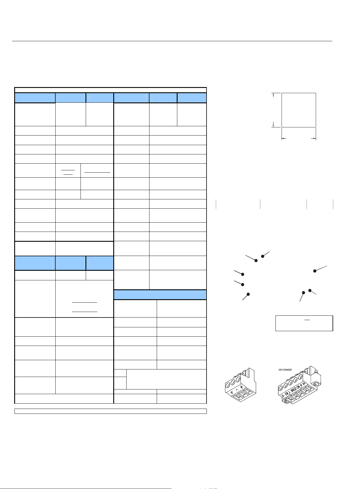
Specifications
Digital DC Inputs XLT103 XLT104
24 including
configurable
HSC inputs
1
35 VDC Max.
10 kΩ
Negative Logic
4
Inputs per Module
Commons per
Module
Input Voltage
Range
Absolute Max.
Voltage
Input Impedance
Input Current
12 including 4
configurable
HSC inputs
12 VDC / 24 VDC
Positive
Logic
Upper Threshold 0.8 mA -1.6 mA
Lower Threshold 0.3 mA -2.1 mA
Max Upper
Threshold
Min Lower
Threshold
OFF to ON
Response
ON to OFF
Response
HSC Max.
Switching Rate
Analog Inputs,
Medium
Resolution
Number of
Channels
Input Ranges
Safe input voltage
range
Input Impedance
(Clamped @ -0.5
VDC to 12 VDC)
10 kHz Totalizer/Pulse,Edges
5 kHz Frequency/Pulse,Width
8 VDC
3 VDC
1 ms
1 ms
2.5 kHz Quadrature
XLT103 XLT104
2 2
0 - 10 VDC
0 – 20 mA
4 – 20 mA
-0.5 V to +12V
Current Mode:
100 Ω
Voltage Mode:
500 k Ω
Nominal Resolution
%AI full scale
Max. Over-Current
Conversion Speed
Max. Error at 25°C
(excluding zero)
Additional error for
temperatures other
than 25°C
Filtering
All channels converted once
10 Bits
32,000 counts
35 mA
per ladder scan
4-20 mA 1.00%
0-20 mA 1.00%
0-10 VDC 0.50%
TBD
160 Hz hash (noise) filter
1-128 scan digital running
average filter
Digital DC
Outputs
Outputs per
Module
Commons per
Module
Output Type
Absolute Max.
Voltage
Output
Protection
Max. Output
Current per
point
Max. Total
Current
Max. Output
Supply Voltage
Minimum Output
Supply Voltage
Max. Voltage
Drop at Rated
Current
Max. Inrush
Current
Min. Load
OFF to ON
Response 1 ms
ON to OFF
Response 1 ms
Output
Characteristics
XLT103 XLT104
12 including
2
configurable
PWM
outputs
16 including
2
configurable
PWM
outputs
1
Sourcing / 10 K Pull-Down
28 VDC Max.
Short Circuit
0.5 A
4 A Continuous
30 VDC
10 VDC
0.25 VDC
650 mA per channel
None
Current Sourcing (Pos logic)
General Specifications
Required Power
(Steady State)
Required Power
(Inrush)
Primary Power
Range
Relative Humidity
Operating
Temperature
Terminal Type
CE
If you requ ire a Compliance Table:
1-888-556-6342
UL
130 mA @ 24 VDC
30 A for 1 ms @ 24 VDC
10 – 30 VDC
5 to 95% Non-
condensing
-10°C to +60°C
Screw Type,5 mm
Removable
Weight 12.5 oz. (354.36 g)
ycaruccA kcolC
+/- Seven
Minutes/Month at 20C
Note: Highest usable frequency for PWM output is 65 KHz
__________________________________________________________________________________________________________________________________________________________________
Page 1 of 4
2 Panel Cut-Out and Dimensions
Note: Max. panel thickness: 5 mm.
3.622 [92mm]
001XLE002
3 Ports / Connectors / Cables
Note: The case of the XLt is black, but for clarity, it is shown in a
lighter gray color.
Switch
MJ2
(RS-232 / RS-485)
MJ1
(RS-232 / RS-485)
J1
I/O
Jumper
To Remove Back Cover:
Unscrew 4 screws located on
the back of the unit and remove
back cover.
I/O Jumpers (Not Shown): I/O Jumpers (JP) are located
internally. To access, remove back cover of unit.
Wiring Connectors (J1 – J4), I/O Jumpers (JP1-3), and
External Jumpers (RS-485) are described in the Wiring and
Jumpers section of this document.
001ACC009
Power Connector
Power Up:
Connect to Earth Ground.
Apply 10 – 30 VDC.
Screen lights up.
Torque rating 4.5 - 7 Lb-In
(0.50 – 0.78 N-m)
Memory Slot
CAUTION: Do not over tighten
CAN Connector
Use the CAN Connector
when using CsCAN network.
Torque rating 4.5 – 7 Lb-In
(0.50 – 0.78 N-m)
Power
cover.
NET 1
(CsCAN)
001XLE029- R2
J2
Jumper
I/O
Page 4
Section 3 continued
DIPSW3:
FACTORY USE
Memory Slot:
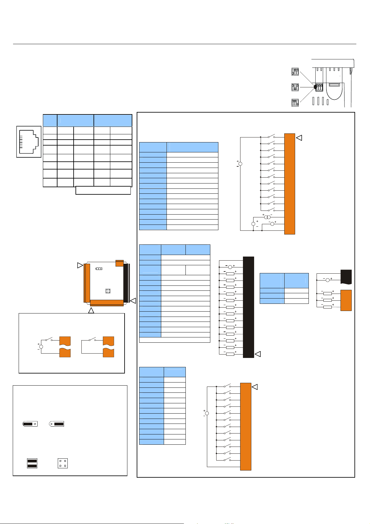
Wiring Specifications
H4
LOAD
LOAD
LOAD
XT104 J4 Orange
Note:
J3
JP1
J4
Uses Removable Memory for data logging, screen
captures, program loading and recipes.
Horner Part No.: HE-MC1
Serial Communications:
MJ1: (RS-232 / RS-485) Use for Cscape programming and
Application-Defined Communications.
MJ2: (RS-232 / RS-485) Use for Application-Defined
Communications.
Pin MJ1 Pins MJ2 Pins
TXD OUT TXD OUT
8
1
8
RXD IN RXD IN
7
0 V Ground 0 V Ground
6
+5
5*
60mA
4
3
RX- /
2
RX+ /
1
OUT
RTS OUT TX- OUT
CTS IN TX+ OUT
TX+
TX-
IN /
OUT
IN /
OUT
* +5Vdc 60mA Max
+5
60mA
RX- IN
RX+ IN
OUT
4 Wiring and Jumpers
•
Wire according to the type of inputs / outputs used and select
the appropriate jumper option. Use Copper Conductors
in Field Wiring Only,
•
For I/O wiring (discrete), use the
following wire type or equivalent:
Belden 9918, 18 AWG (0.8 mm2)
For shielded Analog I/O wiring,
•
use the following wire type or
following wire type or equivalent:
Belden 3084, 24 AWG (0.2 mm2)
or larger.
equivalent: Belden 8441, 18
AWG (0.8 mm
•
For CAN wiring, use the
or larger.
Positive Logic vs. Negative Logic Wiring
The XLt can be wired for Positive Logic inputs or
12-24VDC
6
0/75° C
Location of I/O jumpers (JP)
2
) or larger.
J1 J2
Negative Logic inputs.
I1
0V
and wiring connectors
(J1 – J4).
JP3
I1
0V
001XLE036
Positive Logic In Negative Logic In
4.1 I/O Jumpers Settings (JP1 – JP3)
Note: The Cscape Module Setup configuration must match
the selected I/O (JP) jumper settings.
JP1 Digital DC Inputs
Positive Logic
Default
CURRENT OR VOLTAGE INPUTS
20mA 10VDC
A1
A2
Negative Logic
JP3
A1
A2
11 22
33 44
001XLE043-R1
Note:
When using JP3 (A1-A2),
each channel can be
independently configured.
__________________________________________________________________________________________________________________________________________________________________
4.2 External DIP Switch Settings (or Jumpers Settings)
The External DIP Switches are used for termination of
the RS-485 ports. The XLt is shipped un-terminated.
To terminate, se lect one of the jumpers shipped with
the product and insert it based upon the option that is
desired or, select the switch (as shown in the
illustration) and configure based upon the option that
is desired.
4.3 Wiring Examples
Note: The wiring examples show
Positive Logic input wiring.
J1
Orange
XT103 / XT104
Name
As seen when looking at the top of the XLt unit:
ONLY (tiny bootloader firmware
downloading). NOT TO BE
USED FOR NORMAL OCS
OPERATION.
DIPSW2: MJ2 Termination
(default – none)
DIPSW1: MJ1 Termination
(default – none)
XT103 / 104 J1 Orange
Positive Logic
Digital In
I1 IN1
I2 IN2
I3 IN3
12-24VDC
I4 IN4
I5 IN5
I6 IN6
I7 IN7
I8 IN8
H1 HSC1 / IN9
H2 HSC2 / IN10
H3 HSC3 / IN11
001XLE005-R1
H4 HSC4 / IN12
A1 Analog IN1
A2 Analog IN2
0V Ground
J2
Black
XT103
XT104
0V Ground
V+ V+ *
NC
No
Connect
OUT13
Q12 OUT12
Q11 OUT11
Q10 OUT10
Q9 OUT9
Q8 OUT8
Q7 OUT7
Q6 OUT6
Q5 OUT5
Q4 OUT4
Q3 OUT3
Q2 OUT2 / PWM2
Q1 OUT1 / PWM1
V+* Supply for Sourcing Outputs
J3
Orange
XT104
I13 IN13
I14 IN14
I15 IN15
I16 IN16
I17 IN17
I18 IN18
I19 IN19
I20 IN20
12-24VDC
I21 IN21
I22 IN22
I23 IN23
I24 IN24
0V Ground
XT103 / 104 J2 Black
Positive Logic
Digital Out
10 - 30VDC
LOAD
LOAD
LOAD
LOAD
LOAD
LOAD
LOAD
LOAD
LOAD
LOAD
XT104 J3 Orange
Positive Logic
Digital In
LOOP
PWR
Q13
Q12
Q11
Q10
001XLE024
I13
I14
I15
I16
I17
I18
I19
I20
I21
I22
I23
I24
0V
001XLE047
20mA
0V
V+
Q9
Q8
Q7
Q6
Q5
Q4
Q3
Q2
Q1
0-10VDC
J4
Orange XT104
Q16 OUT16
Q15 OUT15
Q14 OUT14
Page 2 of 4
I1
I2
I3
I4
I5
I6
I7
I8
H1
H2
H3
A1
A2
0V
001XLE046
001XLE03 7-R1
Loop Power requirements
are determined by the
transmitter specification.
Positive Logic
Digital Out
J2
10 - 30VDC
LOAD
LOAD
LOAD
0V
V+
J4
Q16
Q15
Q14
Page 5
5 Filter
60201004080
20
Scans
0
%
C
o
mpl
e
t
e
[
]
Constant
1
8
1
8
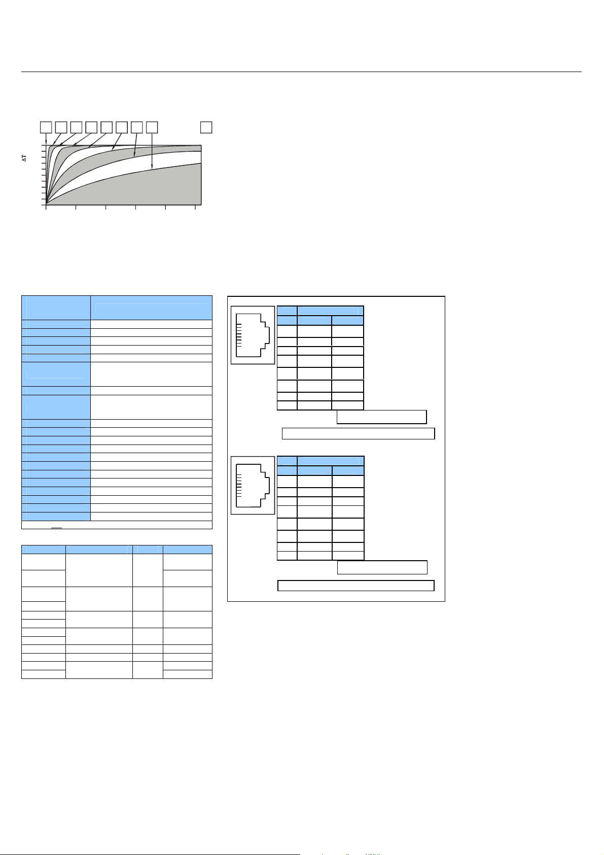
Filter Constant sets the level of digital filtering according to the
following chart.
Filter
100
1 2 3 4 5 60 7
90
80
70
60
50
40
30
10
0
Digital Filtering. The illustration above demonstrates the
effect of digital fil
Constant) on module response to a
temperature change.
g (set with Filter
terin
6 I/O Register Map
Registers Description
%I1 to %I24 Digital Inputs
%I32 Output Fault
%I25 to %I31 Reserved
%Q1 to %Q16 Digital outputs
%Q17 Clear HSC1 accumulator to 0
%Q18
Totalizer: Clear HSC2
Quadrature 1-2: Accumulator 1
Reset to max – 1
%Q19 Clear HSC3 Accumulator to 0
%Q20
Totalizer: Clear HSC4
Quadrature 3-4: Accumulator 3
Reset to max – 1
%Q21 to %Q32 Reserved
%AI1 to %AI4 Analog inputs
%AI5, %AI6 HSC1 Accumulator
%AI7, %AI8 HSC2 Accumulator
%AI9, %AI10 HSC3 Accumulator
%AI11, %AI12 HSC4 Accumulator
%AQ1, %AQ2 PWM1 Duty Cycle
%AQ3, %AQ4 PWM2 Duty Cycle
%AQ5, %AQ6 PWM Prescale
%AQ7, %AQ8 PWM Period
%AQ9 to %AQ14 Analog outputs
Note: Not all XLt units contain the I/O listed in this table.
Registers PWM HSC Stepper
%AQ1
%AQ2
%AQ3
%AQ4
%AQ5
%AQ6
%AQ7
%AQ8
PWM1 Duty
Cycle
(32 bit)
PWM2 Duty
Cycle
(32 bit)
PWM Prescale
(32 bit)
PWM Period
(32 bit)
HSC1
Preset
Value
HSC2
Preset
Value
Start
Frequency
Run
Frequency
Accel Count
(32 bit)
Run Count
(32 bit)
Decel Count
(32 bit)
%Q1 Run
%I30 Ready/Done
%I31
Error
7 MJ2 Pinouts in Full and Half Duplex Modes
Pin MJ2 Pins
Signal Direction
TXD OUT
8
RXD IN
7
0 V Ground
6
+5 60mA OUT
5*
TX- OUT
4
TX+ OUT
3
RX- IN
2
RX+ IN
1
* +5Vdc 60mA max
Full Duplex Mode
Pin MJ2 Pins
Signal Direction
TXD OUT
8
RXD IN
7
0 V Ground
6
+5 60mA OUT
5*
TX- OUT
4
TX+ OUT
3
TX-/RX- IN/OUT
2
TX+/RX+ IN/OUT
1
* +5Vdc 60mA Max
Half Duplex Mode
__________________________________________________________________________________________________________________________________________________________________
Page 3 of 4
Page 6

8 Safety
When found on the product, the following symbols specify:
Warning: Electrical
Shock Hazard.
This equipment is suitable for use in Class I, Division 2, Groups A, B, C and D or Non-hazardous locations only
WARNING – EXPLOSION HAZARD – Substitution of components may impair suitability for Class I, Division 2
AVERTISSEMENT - RISQUE D'EXPLOSION - LA SUBSTITUTION DE COMPOSANTS PEUT RENDRE CE MATERIAL INACCEPTABLE POUR LES EMPLACEMENTS DE
CLASSE 1, DIVISION 2
WARNING – EXPLOSION HAZARD – Do not disconnect equipment unless
AVERTISSEMENT - RISQUE D'EXPLOSION - AVANT DE DECONNECTOR L'EQUIPMENT, COUPER LE COURANT OU S'ASSURER QUE L'EMPLACEMENT EST DESIGNE
NON DANGEREUX.
WARNING: To avoid the risk of electric shock or burns, always connect the safety (or earth) ground before making any other connections.
WARNING: To reduce the risk of fire, electrical shock, or physical injury it is stro
source as possible.
WARNING: Replace fuse with the same type and rating to provide protection against risk of fire and shock hazards.
WARNING: In the event of repeated failure, do not
WARNING: Only qualified electrical personnel familiar with the construction and operation of this equipment and the hazards involved should install, adjust, operate, or service this
equipment. Read and understand this manual and other applicable manuals in their entirety before proceeding. Failure to observe this precaution could result in severe bodily injury
or loss of life.
This device complies with part 15 of the FCC Rules. Operation is subject to the following two conditions:
1. This device may not cause harmful interference.
2. This device must accept any interference received, including interference that may cause undesired operation.
All applicable codes and standards need to be followed in the installation of this product.
•
Adhere to the follo
•
Connect the safety (earth) ground on the power connector first before making any other connections.
•
When connecting to electric circuits or pulse-initiating equipment, open their related breakers.
•
make connections to live power lines.
Do not
•
Make connections to the module first; then connect to the circuit to be monitored.
•
Route power wires in a safe manner in accordance with good practice and local codes.
•
Wear proper personal protective equipment including safety glasses and insulated gloves when making connections to power circuits.
•
Ensure hands, shoes, and floor are dry before making any connection to a power line.
•
Make su
•
•
•
•
re
Make sure all circuits are de-energized before makin
Before each use, inspect all cables for breaks or cracks in the insulation. Replace immediately if defective.
Use Copper Conductors in Field Wiring Only, 60/75° C
wing safety preca
the unit is turned OFF before making connection to terminals.
Warning: Consult
user documentation.
ower has been switched off or the area is known to be non-hazardous.
p
ngly recommended to fuse the voltage measurement inputs. Be sure to locate fuses as close to the
replace the fuse again as a repeated failure indicates a defective condition that will not clear by replacing the fuse.
utions whenever any type of connection is made to the module:
g connections.
__________________________________________________________________________________________________________________________________________________________________
Page 4 of 4
Page 7

WARRANTY/DISCLAIMER
OMEGA ENGINEERING, INC. warrants this unit to be free of defects in materials and workmanship for a
period of 13 months from date of purchase. OMEGA’s WARRANTY adds an additional one (1) month
grace period to the normal one (1) year product warranty to cover handling and shipping time. This
ensures that OMEGA’s customers receive maximum coverage on each product.
If the unit malfunctions, it must be returned to the factory for evaluation. OMEGA’s Customer Service
Department will issue an Authorized Return (AR) number immediately upon phone or written request.
Upon examination by OMEGA, if the unit is found to be defective, it will be repaired or replaced at no
charge. OMEGA’s WARRANTY does not apply to defects resulting from any action of the purchaser,
including but not limited to mishandling, improper interfacing, operation outside of design limits,
improper repair, or unauthorized modification. This WARRANTY is VOID if the unit shows evidence of
having been tampered with or shows evidence of having been damaged as a result of excessive corrosion;
or current, heat, moisture or vibration; improper specification; misapplication; misuse or other operating
conditions outside of OMEGA’s control. Components in which wear is not warranted, include but are not
limited to contact points, fuses, and triacs.
OMEGA is pleased to offer suggestions on the use of its various products. However,
OMEGA neither assumes responsibility for any omissions or errors nor assumes liability for any
damages that result from the use of its products in accordance with information provided by
OMEGA, either verbal or written. OMEGA warrants only that the parts manufactured by it will be
as specified and free of defects. OMEGA MAKES NO OTHER WARRANTIES OR
REPRESENTATIONS OF ANY KIND WHATSOEVER, EXPRESS OR IMPLIED, EXCEPT THAT OF TITLE,
AND ALL IMPLIED WARRANTIES INCLUDING ANY WARRANTY OF MERCHANTABILITY AND
FITNESS FOR A PARTICULAR PURPOSE ARE HEREBY DISCLAIMED. LIMITATION OF
LIABILITY: The remedies of purchaser set forth herein are exclusive, and the total liability of
OMEGA with respect to this order, whether based on contract, warranty, negligence,
indemnification, strict liability or otherwise, shall not exceed the purchase price of the
component upon which liability is based. In no event shall OMEGA be liable for
consequential, incidental or special damages.
CONDITIONS: Equipment sold by OMEGA is not intended to be used, nor shall it be used: (1) as a “Basic
Component” under 10 CFR 21 (NRC), used in or with any nuclear installation or activity; or (2) in medical
applications or used on humans. Should any Product(s) be used in or with any nuclear installation or
activity, medical application, used on humans, or misused in any way, OMEGA assumes no responsibility
as set forth in our basic WARRANTY/ DISCLAIMER language, and, additionally, purchaser will indemnify
OMEGA and hold OMEGA harmless from any liability or damage whatsoever arising out of the use of the
Product(s) in such a manner.
RETURN REQUESTS/INQUIRIES
Direct all warranty and repair requests/inquiries to the OMEGA Customer Service Department. BEFORE
RETURNING ANY PRODUCT(S) TO OMEGA, PURCHASER MUST OBTAIN AN AUTHORIZED RETURN
(AR) NUMBER FROM OMEGA’S CUSTOMER SERVICE DEPARTMENT (IN ORDER TO AVOID
PROCESSING DELAYS). The assigned AR number should then be marked on the outside of the return
package and on any correspondence.
The purchaser is responsible for shipping charges, freight, insurance and proper packaging to prevent
breakage in transit.
FOR WARRANTY
RETURNS, please have the
following information available BEFORE
contacting OMEGA:
1. Purchase Order number under which the product
was PURCHASED,
2. Model and serial number of the product under
warranty, and
3. Repair instructions and/or specific problems
relative to the product.
FOR NON-WARRANTY REPAIRS,
consult OMEGA
for current repair charges. Have the following
information available BEFORE contacting OMEGA:
1. Purchase Order number to cover the COST
of the repair,
2. Model and serial number of the product, and
3. Repair instructions and/or specific problems
relative to the product.
OMEGA’s policy is to make running changes, not model changes, whenever an improvement is possible. This affords
our customers the latest in technology and engineering.
OMEGA is a registered trademark of OMEGA ENGINEERING, INC.
© Copyright 2009 OMEGA ENGINEERING, INC. All rights reserved. This document may not be copied, photocopied,
reproduced, translated, or reduced to any electronic medium or machine-readable form, in whole or in part, without the
prior written consent of OMEGA ENGINEERING, INC.
Page 8

M4758/0109
OME0872-04-EN
Where Do I Find Everything I Need for
Process Measurement and Control?
OMEGA…Of Course!
Shop online at omega.com
sm
TEMPERATURE
䡺⻬
Thermocouple, RTD & Thermistor Probes, Connectors, Panels & Assemblies
䡺⻬
Wire: Thermocouple, RTD & Thermistor
䡺⻬
Calibrators & Ice Point References
䡺⻬
Recorders, Controllers & Process Monitors
䡺⻬
Infrared Pyrometers
PRESSURE, STRAIN AND FORCE
䡺⻬
Transducers & Strain Gages
䡺⻬
Load Cells & Pressure Gages
䡺⻬
Displacement Transducers
䡺⻬
Instrumentation & Accessories
FLOW/LEVEL
䡺⻬
Rotameters, Gas Mass Flowmeters & Flow Computers
䡺⻬
Air Velocity Indicators
䡺⻬
Turbine/Paddlewheel Systems
䡺⻬
Totalizers & Batch Controllers
pH/CONDUCTIVITY
䡺⻬
pH Electrodes, Testers & Accessories
䡺⻬
Benchtop/Laboratory Meters
䡺⻬
Controllers, Calibrators, Simulators & Pumps
䡺⻬
Industrial pH & Conductivity Equipment
DATA ACQUISITION
䡺⻬
Data Acquisition & Engineering Software
䡺⻬
Communications-Based Acquisition Systems
䡺⻬
Plug-in Cards for Apple, IBM & Compatibles
䡺⻬
Data Logging Systems
䡺⻬
Recorders, Printers & Plotters
HEATERS
䡺⻬
Heating Cable
䡺⻬
Cartridge & Strip Heaters
䡺⻬
Immersion & Band Heaters
䡺⻬
Flexible Heaters
䡺⻬
Laboratory Heaters
ENVIRONMENTAL
MONITORING AND CONTROL
䡺⻬
Metering & Control Instrumentation
䡺⻬
Refractometers
䡺⻬
Pumps & Tubing
䡺⻬
Air, Soil & Water Monitors
䡺⻬
Industrial Water & Wastewater Treatment
䡺⻬
pH, Conductivity & Dissolved Oxygen Instruments
 Loading...