

Page 1
TM
Guida per
l'utente
Acquista
online su
omega.com
e-mail: [email protected]
Per i manuali più recenti
dei prodotti:
www.omegamanual.info
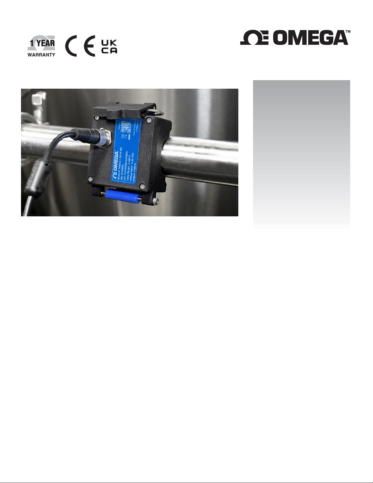
Sensore di temperatura a
morsetto HANI™
Sensore di temperatura a morsetto non
invasivo ad alta precisione
Page 2

omega.com [email protected]
Assistenza per il Nord America:
Omega Engineering, Inc.
800 Connecticut Ave. Suite 5N01, Norwalk, CT 06854
Numero verde: 1-800-826-6342 (solo USA e Canada)
Servizio clienti: 1-800-622-2378 (solo USA e Canada)
Assistenza tecnica: 1-800-872-9436 (solo per USA e
Stati Uniti
Sede centrale:
Tel: (203) 359-1660
e-mail: [email protected]
Fax: (203) 359-7700
Le informazioni contenute nel presente documento sono da ritenersi corrette; tuttavia OMEGA non si assume alcuna responsabilità per gli errori
eventualmente presenti e si riserva il diritto di modificare le specifiche senza preavviso.
Page 3

Sommario
Table of Contents ............................................................................................................................................................3
1) Introduction ............................................................................................................................................................4
1.1 HANI™ Clamp Temperature Sensor Mounting ...................................................................................................5
2) Wiring Diagram .......................................................................................................................................................6
2.1 M12 8-Pin Connector ........................................................................................................................................6
2.1.1 4-20 mA Process Signals ....................................................................................................................................... 6
3) 4-20 mA Plug and Play .............................................................................................................................................6
4) SYNC Configuration..................................................................................................................................................7
4.1 Configuring Inputs ............................................................................................................................................7
4.1.1 Calibration ............................................................................................................................................................ 9
4.1.2 Setting Alarms .................................................................................................................................................... 11
4.2 Configuring Device Settings ............................................................................................................................ 11
4.2.1 Transmit Interval ................................................................................................................................................ 12
4.2.2 Setting/Changing Passwords .............................................................................................................................. 12
4.3 Data Logging .................................................................................................................................................. 14
5) 4-20mA Loop-Powered Output............................................................................................................................... 15
5.1 Sensor Mapping ............................................................................................................................................. 15
5.1.1 4-20 mA Outputs Sensor Mapping ..................................................................................................................... 16
6) Specifications ........................................................................................................................................................ 17
7) Appendix: HANI™ Clamp Temperature Sensor Input Interface ................................................................................ 18
7.1 Register Base Addresses ................................................................................................................................. 18
7.2 HANI™ Clamp Temperature Sensor Temperature Input Interface ..................................................................... 18
7.2.1 Sensor Input Descriptor...................................................................................................................................... 18
7.2.2 Sensor Temperature Parameters ....................................................................................................................... 20
7.2.3 Sensor User Calibration Parameters .................................................................................................................. 21
7.2.4 Sensor IPSO Definition........................................................................................................................................ 21
7.3 DIO Interface.................................................................................................................................................. 23
7.3.1 DIO Descriptor .................................................................................................................................................... 23
7.3.2 DIO IPSO Definition ............................................................................................................................................ 25
7.4 Output Configuration Registers ...................................................................................................................... 26
7.4.1 Scaling Minimum / Maximum Values................................................................................................................. 26
7.4.2 Output Values ..................................................................................................................................................... 26
7.4.3 Output Names .................................................................................................................................................... 27
7.5 4-20 mA Output Configuration ........................................................................................................................ 27
7.5.1 High Range / Low Range ..................................................................................................................................... 28
7.5.2 System Error ....................................................................................................................................................... 28
7.5.3 Output Type........................................................................................................................................................ 28
7.5.4 Mapping Enabled ............................................................................................................................................... 28
7.5.5 Output Mapping ................................................................................................................................................. 28
7.5.6 Scaling Minimum/Maximum Values .................................................................................................................. 28
7.5.7 4-20 mA Loop Powered Error ............................................................................................................................. 28
7.6 Digital Output Configuration ........................................................................................................................... 29
7.6.1 Rate .................................................................................................................................................................... 29
7.6.2 Output Type........................................................................................................................................................ 30
7.6.3 Active State......................................................................................................................................................... 30
7.6.4 Mapping Enabled ............................................................................................................................................... 30
7.6.5 Output Mapping ................................................................................................................................................. 30
Page 4
1) Introduzione
L'innovativa tecnologia di Omega Engineering per il rilevamento non invasivo della temperatura offre i risultati di un
sensore a immersione senza costi di installazione, danni, sostituzione e calibrazione che si verificano con un sensore a
immersione. Il sensore di temperatura a morsetto HANI™ rende più semplice che mai la misurazione della temperatura di
un fluido che scorre attraverso un tubo. Non sono necessari tagli o saldature. È sufficiente fissare il sensore a morsetto
all'esterno del tubo e iniziare a misurare la temperatura del fluido all'interno del tubo. Il sensore di temperatura a morsetto
HANI™ offre una precisione e tempi di risposta equivalenti ai sensori di temperatura a immersione all'avanguardia. Questo
sensore è molto più facile da installare e gestire, con un costo totale inferiore.
Il sensore di temperatura a morsetto HANI™ è progettato per essere utilizzato in combinazione con un collegamento da 4-
20 mA per uscita analogica plug-and-play o con un'interfaccia Layer N Smart per utilizzare funzioni personalizzabili mediante
il software di configurazione SYNC di Omega attraverso un connettore M12 integrato.
Page 5
1.1 Montaggio del sensore di temperatura a morsetto HANI™
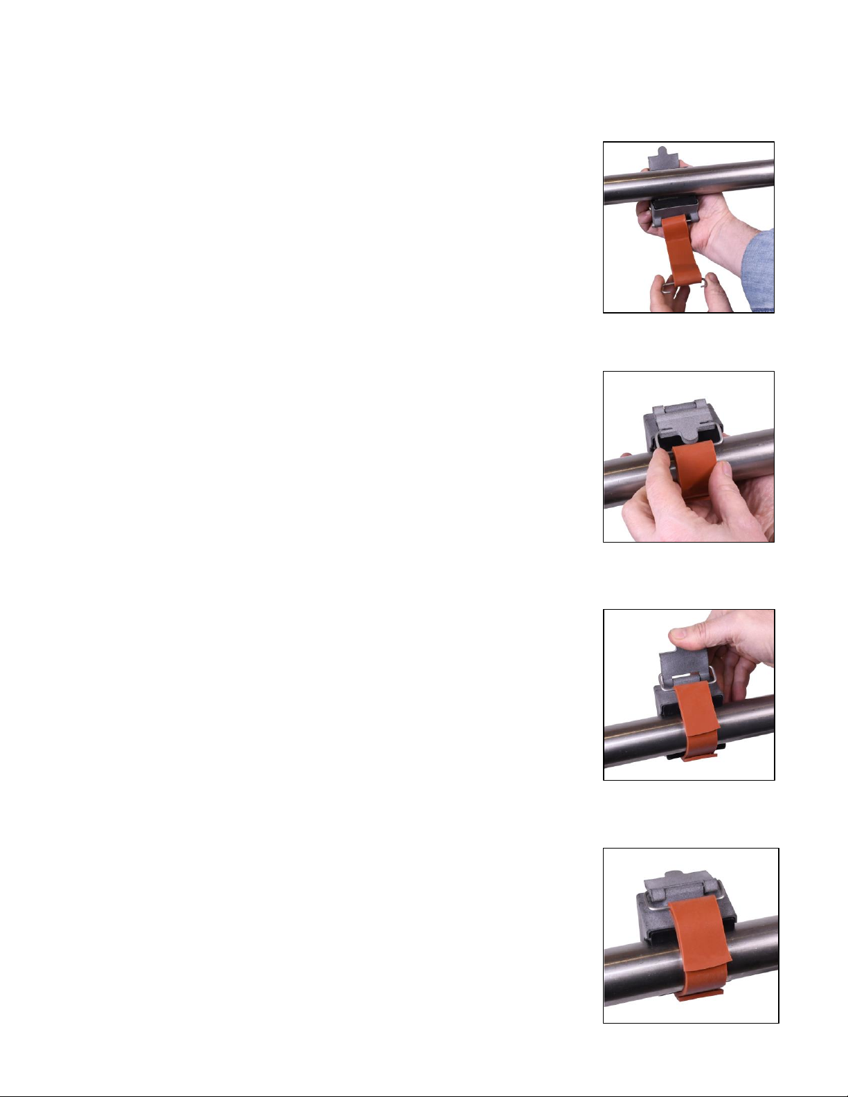
La configurazione sul campo del sensore di temperatura a morsetto HANI™ è rapida e semplice. Seguire le
istruzioni riportate di seguito:
Fase 1: montare l'alloggiamento del sensore di temperatura a morsetto
HANI™ sul tubo
per il quale si effettua la misurazione. Il dispositivo deve essere
montato sul lato o nella parte inferiore di un tubo orizzontale per
assicurarsi di rilevare un'area piena di liquido.
Fase 2: far scorrere l'estremità del morsetto nei canali laterali della leva a
camma.
Fase 3: tirare il meccanismo a camma per serrare saldamente il sensore di
temperatura a morsetto HANI™
sul tubo.
Una volta fissato il meccanismo a camma sul tubo, il processo di montaggio è
completo.
Page 6
2) Schema elettrico
2.1 Connettore M12 a 8 pin
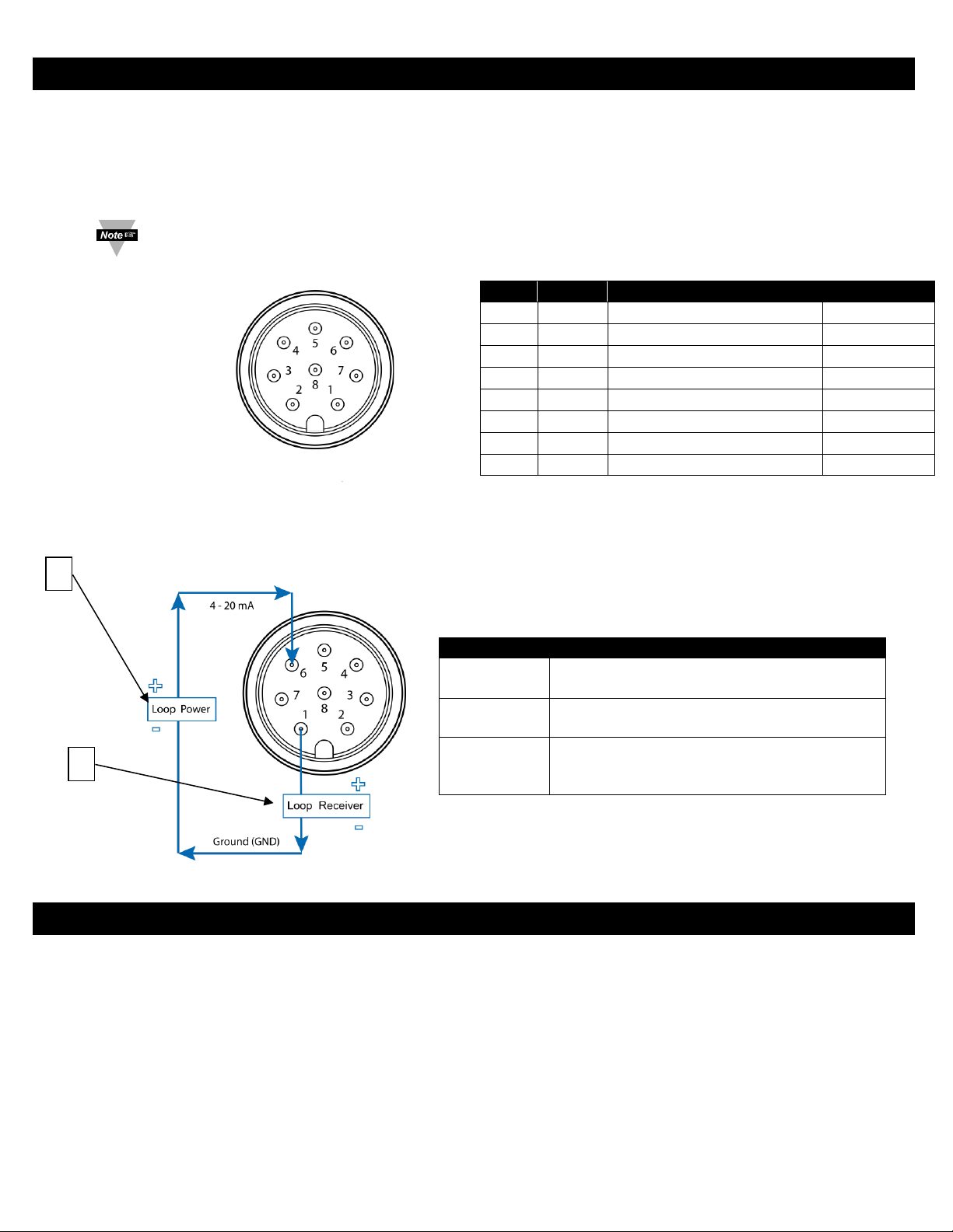
Il sensore di temperatura a morsetto HANI™ si collega a un collegamento da 4-20 mA o a un'interfaccia Layer N
Smart attraverso un connettore di accoppiamento femmina M12 a 8 pin. Il connettore supporta le linee di segnale
I2C + INTR richieste e i segnali di alimentazione della sonda Smart.
Nota: l'immagine riportata di seguito mostra l'estremità aperta del connettore di accoppiamento femmina
M12 a 8 pin e non il connettore maschio integrato sul sensore di temperatura a morsetto HANI™.
2.1.1 Segnali di processo 4-20 mA
Fare riferimento al seguente schema elettrico del sensore a morsetto HANI™ in questa sezione per
impostare i segnali di processo a 4-20 mA.
3) Plug and Play da 4-20 mA
Il sensore di temperatura a morsetto HANI™ può essere facilmente integrato nel sistema analogico esistente in pochi
passaggi. Per utilizzare immediatamente la funzione Plug and Play da 4-20 mA, procedere come indicato di seguito:
Fase 1: montare e fissare il sensore di temperatura a morsetto HANI ™ sul tubo per il quale si effettua la
misurazione.
Fase 2: collegare un connettore femmina M12 a 8 pin al cavo analogico da 4-20 mA (vedere lo schema elettrico
del sensore di temperatura a morsetto HANI™ in alto – sono necessari solo i pin 1 e 6).
Il sensore di temperatura a morsetto HANI™ inizierà immediatamente a riportare le letture della temperatura.
Nome
Funzione
Cablaggio
Pin 1
Loop -
Ritorno 4-20 mA
4-20 mA
Pin 2
INTR
Segnale di interruzione
Layer N
Pin 3
SCL
Segnale di clock I2C
Layer N
Pin 4
SDA
Segnale dati I2C
Layer N
Pin 5
Shield
Messa a terra schermatura
Layer N
Pin 6
Loop +
Sorgente 4-20 mA
4-20 mA
Pin 7
GND
Massa alimentazione
Layer N
Pin 8
VCC
Alimentazione
Layer N
Nome
Descrizione
Alimentazione
loop [1]
Fornisce una tensione di "eccitazione" al sensore,
in genere 12-24 VCC.
Sensore
Controlla la corrente che passa attraverso il
circuito in base al valore misurato.
Ricevitore
loop [2]
Converte il segnale da 4-20 mA e visualizza o
trasmette il valore misurato. Ciò include controller
PID e controller logici programmabili.
Connettore di
1
2
Page 7
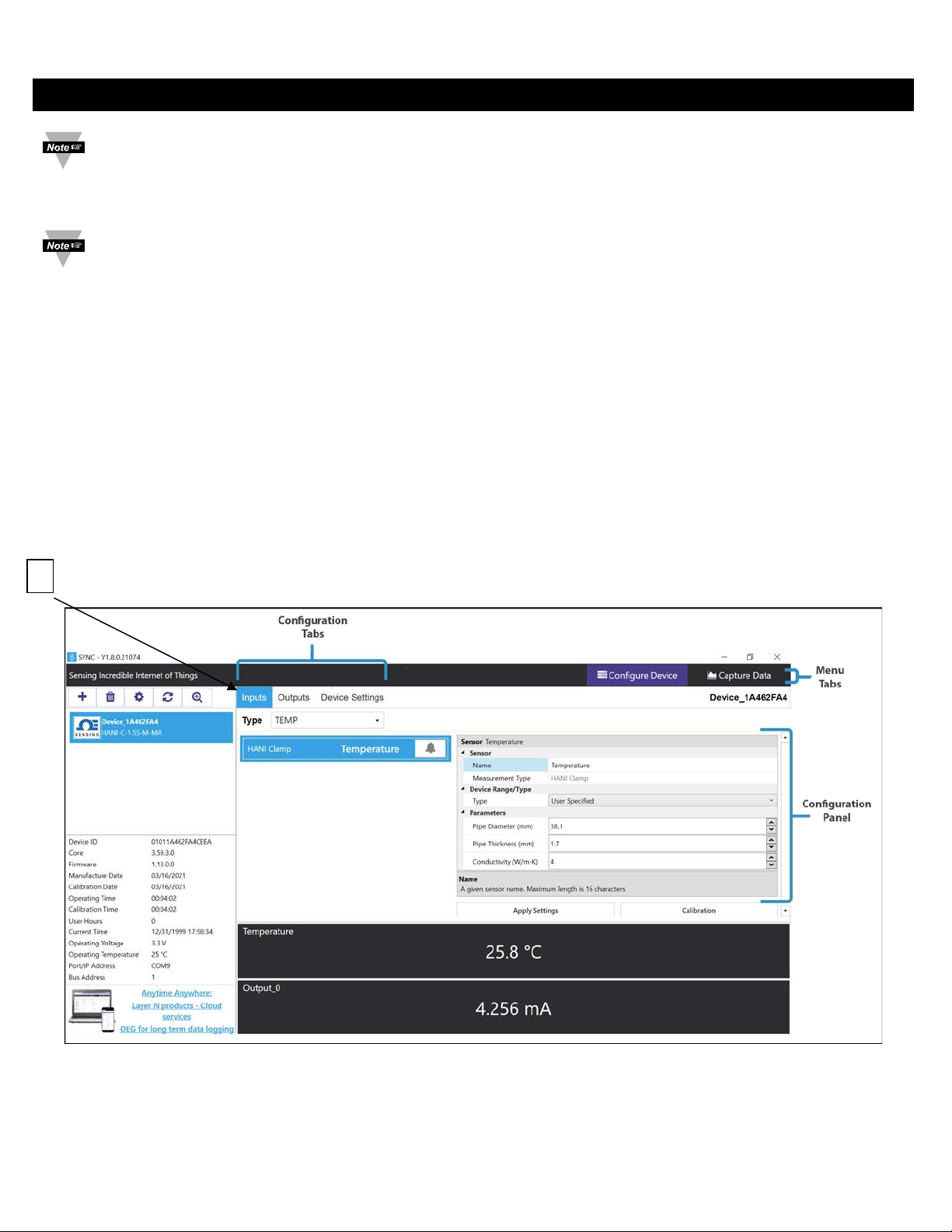
4) Configurazione SYNC
Importante: La configurazione SYNC è necessaria solo se si modificano il diametro del tubo, il tipo di materiale del
tubo, la conduttività del tubo o per scalare le letture dell'uscita. Prima di continuare, verificare che il software di
configurazione SYNC di Omega sia stato scaricato, configurato ed eseguito. Assicurarsi di disporre di un'interfaccia,
ad esempio IF-001 o IF-006, compatibile con il sensore di temperatura a morsetto HANI™.
Importante: se il sensore di temperatura a morsetto HANI™ è alimentato tramite un collegamento da 4-20 mA e
viene configurato utilizzando contemporaneamente SYNC, è necessario utilizzare un isolatore USB tra il PC utente e
il sensore di temperatura a morsetto HANI™ per evitare letture errate e potenziali danni all'unità.
Il sensore di temperatura a morsetto HANI™ può essere configurato utilizzando il software di configurazione SYNC di Omega
quando il sensore di temperatura a morsetto HANI™ è collegato tramite un'interfaccia Layer N Smart a un computer su cui è
in esecuzione SYNC. A seconda dell'interfaccia Layer N Smart utilizzata, il processo di collegamento può variare
leggermente. Fare riferimento alla documentazione per l'utente dell'interfaccia Layer N Smart in uso.
Una volta collegato il sensore di temperatura a morsetto HANI™ a SYNC, le letture vengono visualizzate immediatamente
sull'interfaccia SYNC.
4.1 Configurazione degli ingressi
Il software di configurazione SYNC di Omega può essere utilizzato per configurare il sensore di temperatura a
morsetto HANI™ in base ai parametri dell'applicazione. Per configurare un sensore di temperatura a morsetto
HANI™ collegato a un'interfaccia Layer N Smart tramite SYNC, accedere alla scheda di configurazione Inputs [3]
(Ingressi) dell'interfaccia SYNC.
3
Page 8
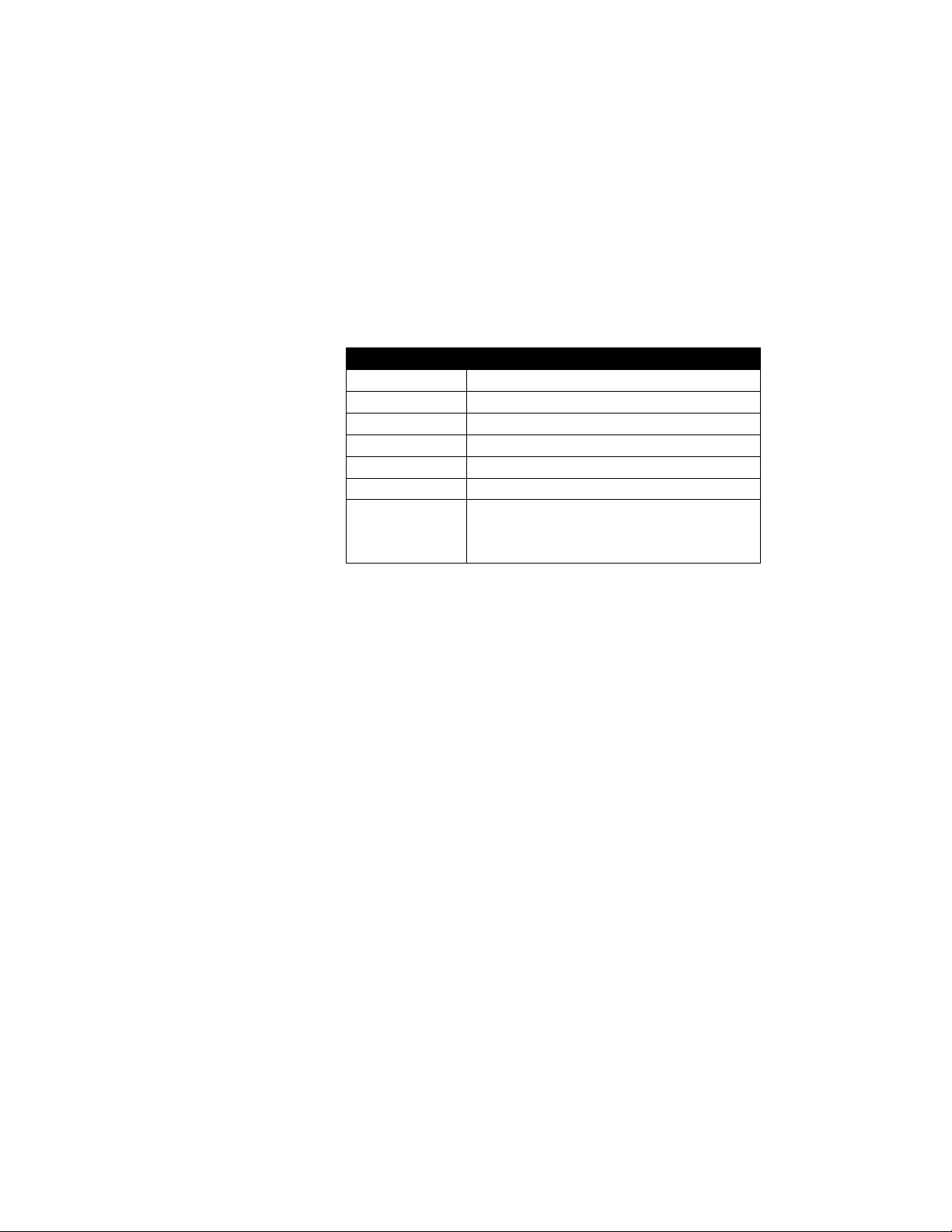
Nella scheda di configurazione Inputs [3] (Ingressi) verranno visualizzate tutte le opzioni di configurazione per gli
ingressi del sensore di temperatura a morsetto HANI™. I sensori di temperatura a morsetto HANI™ sono
preconfigurati per tubi in ACCIAIO INOX con parete di spessore standard. Lo spessore del tubo dei dispositivi
sanitari non deve essere modificato. I tubi dei dispositivi industriali vengono forniti preconfigurati con spessori
(standard) Schedule 40. Se il tubo è realizzato in un materiale diverso dall'acciaio inox e/o ha uno spessore non
standard, seguire le istruzioni di calibrazione riportate di seguito. Per accertarsi che il sensore di temperatura a
morsetto HANI™ fornisca misurazioni precise, il diametro e lo spessore del tubo devono essere impostati
correttamente.
Fase 1: per configurare il materiale del tubo, andare alla sezione Device Range/Type (Gamma/tipo dispositivo)
dell'interfaccia utente SYNC e
scegliere l'elenco a discesa Type (Tipo) per il materiale metallico appropriato del tubo in base alla
tabella seguente:
Tipo
Materiale
SS
Acciaio inox
CS
Acciaio al carbonio (1% C)
GS
Acciaio zincato
CU
Rame
BR
Ottone giallo (70% Cu/30% Zn)
AL
Alluminio
Specificato
dall'utente
Personalizzato: valore di conducibilità
termica scalabile dall'utente per tubi
personalizzati
Se il tipo di materiale del tubo non è incluso in questo elenco preimpostato, selezionare User Specified (Specificato
dall'utente) per visualizzare un campo aggiuntivo in corrispondenza di Conductivity (W/mK) (Conduttività W/mK).
Inserire la conduttività termica del tubo personalizzato in questo campo aggiuntivo. Per assistenza nella scelta del
valore appropriato, contattare Omega Engineering.
Fase 2: per configurare lo spessore di un tubo non standard, accedere alla sezione Parameters (Parametri) e
impostare Pipe
Thickness (mm) (Spessore tubo mm) allo spessore di parete appropriato, in millimetri.
Fase 3: l'opzione Pipe Diameter (mm) (Diametro tubo mm) deve essere preconfigurato al diametro esterno
effettivo del tubo, in base alla
SKU ordinata, ma questo valore può essere modificato se utilizzato su tubi di altri diametri.
Fase 4: una volta completata la configurazione degli ingressi del sensore di temperatura a morsetto HANI™,
fare clic su Apply
Settings (Applica impostazioni) finalizzare le modifiche.
Page 9
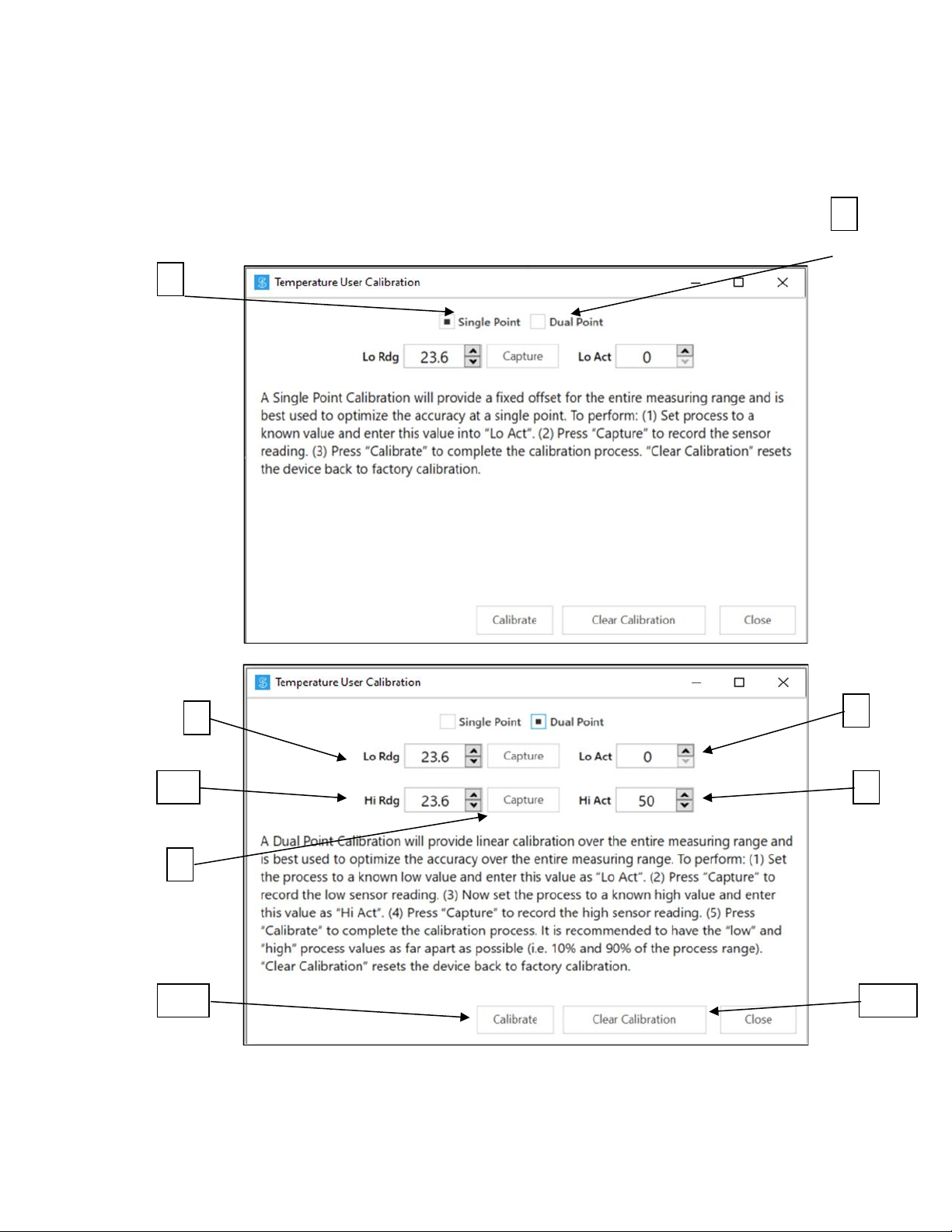
4.1.1 Calibrazione
Il sensore di temperatura a morsetto HANI™ è dotato di una calibrazione standard a 2 punti eseguita in
fabbrica, ma a volte, per ottimizzare la precisione nell'applicazione dell'utente è necessario effettuare una
User Calibration (Calibrazione dell'utente). È possibile eseguire una Single-Point [4] o Dual-Point [5] User
Calibration (Calibrazione utente a punto singolo [4] o a punto doppio [5]) tramite il software di
configurazione SYNC di Omega. Per eseguire una calibrazione corretta, la temperatura all'interno del tubo
deve essere nota o misurabile con un sensore a immersione. Questo valore di temperatura del sensore a
immersione verrà utilizzato per calibrare il sensore di temperatura a morsetto HANI™ in base a una delle due
procedure seguenti:
5 4 6 9 7
10 8 11
12
Page 10
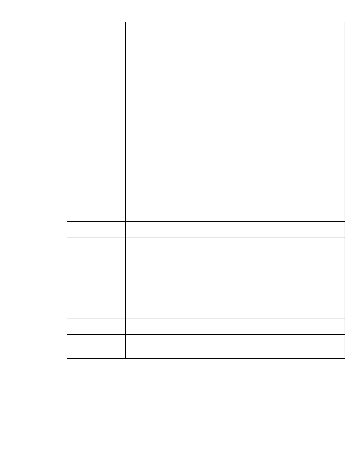
Single-Point User
Calibration
[4](Calibrazione
utente a punto
singolo):
Una calibrazione a punto singolo fornisce un offset fisso per l'intero intervallo di
misurazione e consente di ottimizzare la precisione in un singolo punto. Per
eseguire questa operazione, (1) impostare il processo su un valore noto e
inserire questo valore in Lo Act (Eff. basso). (2) Premere Capture (Acquisisci) per
registrare la lettura del sensore. (3) Premere Calibrate (Calibra) per completare
il processo di calibrazione. Clear Calibration (Cancella calibrazione) riporta il
dispositivo alla calibrazione di fabbrica.
Dual-Point User
Calibration [5]
(Calibrazione
utente a doppio
punto):
Una calibrazione a doppio punto fornisce una calibrazione lineare sull'intero
intervallo di misurazione e consente di ottimizzare la precisione nell'intero
intervallo di misurazione. Per eseguire: (1) impostare il processo su un valore
basso noto e inserire questo valore come Lo Act (Eff. basso). (2) Premere
Capture (Acquisisci) per registrare la lettura del sensore bassa. (3) Impostare il
processo su un valore alto noto e inserire questo valore come Hi Act (Eff.
alto). (4) Premere Capture (Acquisisci) per registrare la lettura alta del sensore.
(5) Premere Calibrate (Calibra) per completare il processo di calibrazione. È
opportuno che i valori di processo "basso" e "alto" siano più distanti possibile
tra loro (ad es. 10% e 90% dell'intervallo di processo). Clear Calibration
(Cancella calibrazione) riporta il dispositivo alla calibrazione di fabbrica.
Low Actual [6]
(Effettivo basso):
Il valore del processo effettivo a bassa temperatura, misurato dal sensore a
immersione di riferimento nella linea di processo. Per le Single-Point
Calibrations (Calibrazioni a punto singolo) è possibile scegliere qualsiasi
temperatura nell'intervallo di processo del sensore. Per le Dual-Point
Calibrations (Calibrazioni a doppio punto) si consiglia di scegliere una
temperatura all'estremità inferiore dell'intervallo di processo del sensore
(20 °C).
Low Reading [7]
(Lettura bassa):
Il valore di processo basso letto dal sensore di temperatura a morsetto HANI™.
Capture [8]
(Acquisisci):
Il pulsante Capture (Acquisisci) rileva una lettura in tempo reale dal sensore di
temperatura a morsetto HANI™ e inserisce il valore in Low Reading (Lettura
bassa) o High Reading (Lettura alta), come indicato.
High Actual [9]
(Effettivo alto):
Il valore del processo effettivo ad alta temperatura, misurato dal sensore a
immersione di riferimento nella linea di processo. Non applicabile per
calibrazioni a punto singolo. Per le calibrazioni a doppio punto si consiglia di
scegliere una temperatura all'estremità superiore dell'intervallo di processo del
sensore (80 °C).
High Reading [10]
(Lettura alta):
Il valore di processo alto letto dal sensore di temperatura a morsetto HANI™.
Calibrate [11]
(Calibra):
Il pulsante Calibrate (Calibra) calcola e calibra la nuova pendenza e il nuovo
offset in base alle letture e ai valori effettivi inseriti in precedenza.
Clear Calibration
[12] (Cancella
calibrazione):
Questo pulsante cancella i valori User Calibration (Calibrazione utente)
precedentemente inseriti e, di conseguenza, riporta il sensore di temperatura a
morsetto HANI™ alla calibrazione di fabbrica.
Page 11
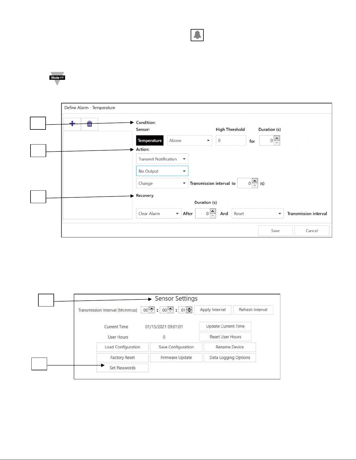
4.1.2 Impostazione degli allarmi
Gli allarmi vengono impostati facendo clic sull'icona in SYNC sul segnale di ingresso evidenziato nella
scheda di configurazione Inputs (Ingressi). Impostare la soglia e il tipo di allarme nella sezione Condition [13]
(Condizione), quindi selezionare l'uscita da attivare nella sezione Action [14] (Azione). L'allarme può essere
impostato in modo che sia bloccato o non bloccato nella sezione Recovery [15] (Recupero).
Nota: le uscite degli allarmi sono disponibili solo sui modelli con uscita digitale al momento; i prodotti
con uscite analogiche non supportano le uscite degli allarmi, ma sono comunque in grado di
trasmettere le notifiche al cloud Layer N.
4.2 Configurazione delle impostazioni del dispositivo
Il software di configurazione SYNC di Omega può essere utilizzato per configurare le impostazioni del dispositivo
del sensore di temperatura a morsetto HANI™. Per configurare le impostazioni del dispositivo, accedere alla
scheda di configurazione Device Settings [17] (Impostazioni dispositivo) dell'interfaccia SYNC.
13
14
15
16
18
Page 12
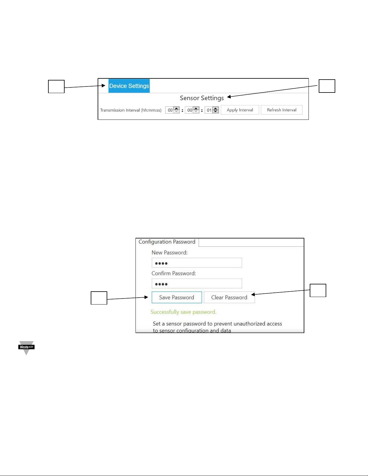
4.2.1 Intervallo di trasmissione
L'intervallo di trasmissione può essere regolato accedendo alla scheda Device Settings (Impostazioni
dispositivo) nell'interfaccia SYNC e verrà visualizzato sotto la sezione Sensor Settings [16] (Impostazioni
sensore). L'intervallo di trasmissione determina il tempo tra le letture del sensore di temperatura a morsetto
HANI™. L'intervallo di trasmissione verrà inoltre ripristinato all'intervallo minimo in base all'account cloud
Layer N non appena il dispositivo viene associato al cloud Layer N.
4.2.2 Impostazione/modifica delle password
I dati del sensore di temperatura a morsetto HANI™ possono essere protetti da password tramite SYNC. La
protezione tramite password del sensore di temperatura a morsetto HANI™ impedisce l'estrazione dei dati
del dispositivo senza autorizzazione. Se la sonda Smart è protetta da password, la password deve essere
memorizzata anche nell'interfaccia Layer N Smart in modo da poter trasmettere i dati al cloud Layer N. Per
assegnare una password al sensore di temperatura a morsetto HANI™, attenersi alle seguenti istruzioni:
Fase 1: accedere alla scheda Device Settings [17] (Impostazioni dispositivo) nell'interfaccia SYNC e fare
clic su Set Passwords [18] (Imposta password) nella sezione Sensor Settings [16] (Impostazioni sensore).
Fase 2: creare una password di configurazione. Dopo aver salvato la password, verrà richiesto di eseguire
l'aggiornamento
della password dell'interfaccia per garantire la trasmissione dei dati al cloud Layer N.
Importante: se la password dell'interfaccia non corrisponde alla password di configurazione, i dati delsensore di
temperatura a morsetto HANI™ non verranno inviati al cloud Layer N.
4.2.2.1 Save Password [19] (Salva password)
La password protegge le funzioni configurabili SYNC del sensore di temperatura a morsetto HANI™ e
salva la nuova password se questa viene inserita e confermata correttamente in entrambi i campi di
testo.
4.2.2.2 Clear Password [20] (Cancella password)
Il pulsante Clear Password (Cancella password) rimuove la protezione tramite password dalla sonda.
17
16
19
20
Page 13
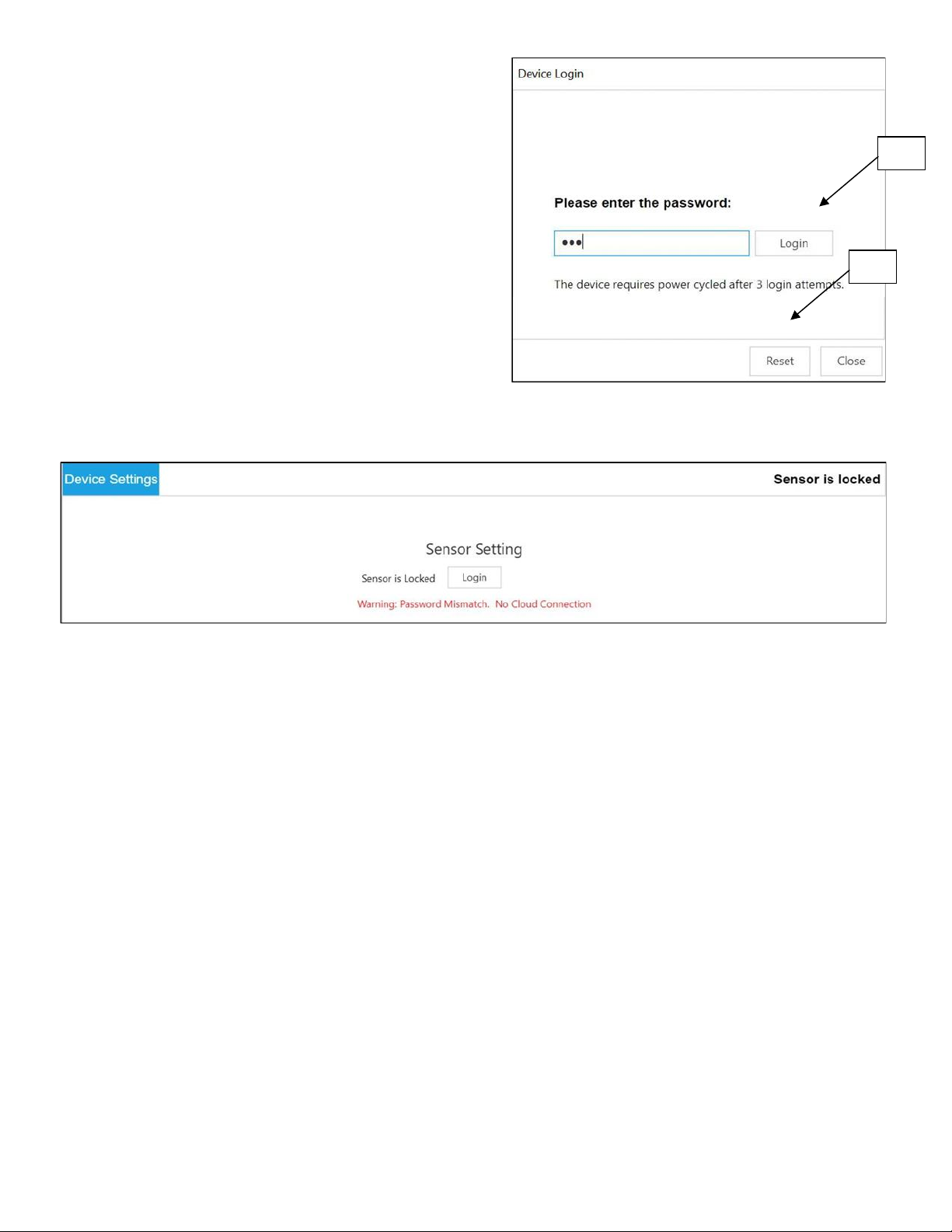
4.2.2.3 Login [21] (Accedi)
Fare clic sul pulsante Login (Accedi) dopo
aver inserito la password del dispositivo per
accedere alle funzioni configurabili.
4.2.2.4 Reset [22] (Ripristina)
Il pulsante Reset Password (Ripristina
password) elimina la password corrente sul
dispositivo. In questo modo tutti i dati
registrati saranno cancellati.
Dopo 3 tentativi di accesso non riusciti, è necessario spegnere e riaccendere il dispositivo prima di ripetere l'accesso.
21
22
Page 14
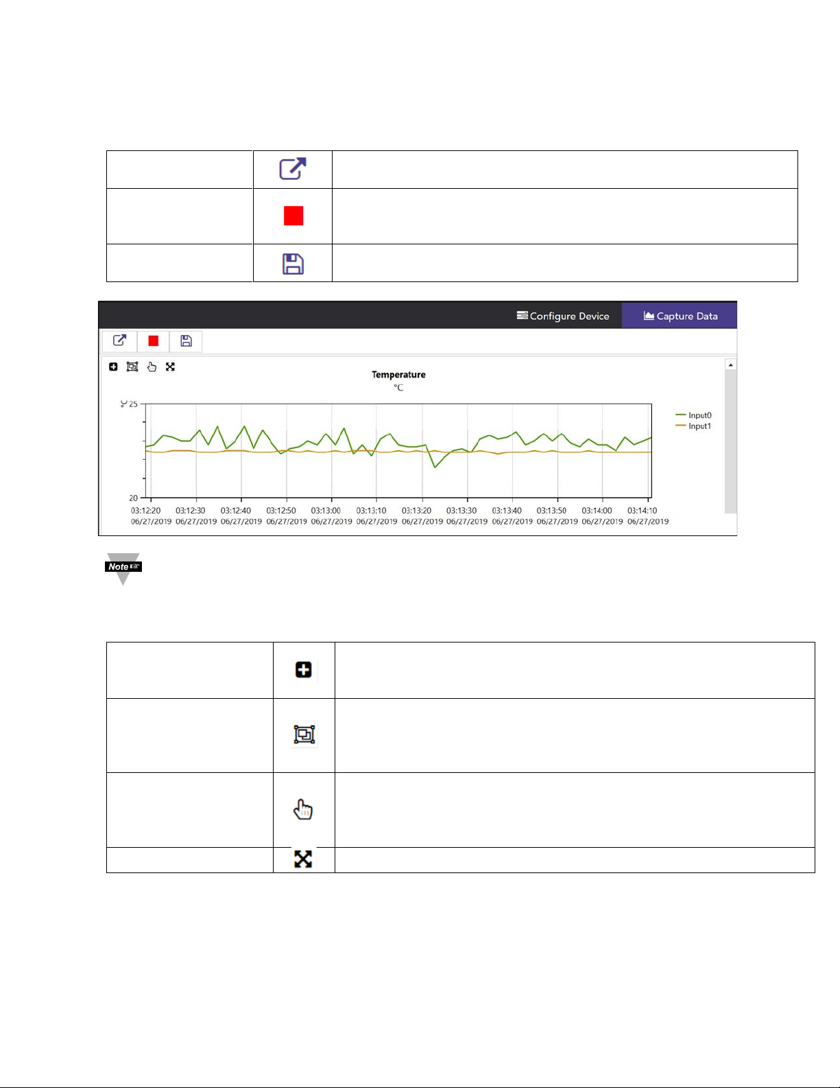
4.3 Registrazione dati
L'interfaccia Capture Data (Acquisizione dati) fornisce un grafico che visualizza i dati in tempo reale provenienti dai
sensori di temperatura a morsetto HANI™ collegati. L'interfaccia Capture Data (Acquisizione dati) contiene le
seguenti funzioni:
Extract Data (Estrai
dati)
Estrae i dati dal registratore di dati del dispositivo.
Start/Stop Recording
(Avvia/arresta
registrazione)
Attiva/disattiva la visualizzazione dei dati in tempo reale.
Export Data to CSV
(Esporta dati in CSV)
Raccoglie i dati registrati o estratti e li salva in un file CSV.
Nota: i dati verranno ripristinati se l'utente passa all'interfaccia Configure device (Configura dispositivo).
La funzione di acquisizione dati di SYNC consente la registrazione dei dati a breve termine.
SYNC offre quattro modi per spostarsi nell'interfaccia di acquisizione dati:
Zoom by Rectangle
(Zoom su rettangolo)
Consente all'utente di fare clic con il pulsante sinistro del mouse e
trascinare il mouse sui dati del grafico per creare un rettangolo da
ingrandire.
Zoom by Middle Mouse
Wheel (Zoom con
rotellina centrale del
mouse)
Consente all'utente di ingrandire e ridurre i dati del grafico utilizzando la
rotellina centrale del mouse. Questo vale solo per gli utenti che dispongono
di un mouse dotato di rotellina in grado di eseguire la funzione necessaria.
Pan by Left Mouse
Button (Panoramica con
il pulsante sinistro del
mouse)
Consente all'utente di fare clic con il pulsante sinistro del mouse e di
trascinare i dati del grafico nella direzione del mouse.
Reset (Ripristino)
Ripristina i dati del grafico nella posizione originale.
Page 15
5) Uscita con alimentazione loop da 4-20 mA
I dispositivi configurati per l'alimentazione loop da 4-20 mA disattivano gli ingressi DIO e le uscite digitali.
Le uscite da 4-20 mA sono ampiamente utilizzate grazie ai numerosi vantaggi delle uscite di sovratensione:
• Maggiore immunità ai disturbi
• Capacità di alimentare il dispositivo di rilevamento utilizzando la corrente di misurazione: la potenza totale fornita è
inferiore a ~ 3,5 mA * di tensione di loop minima
• Rilevamento automatico interruzione fili: se i fili del segnale sono in cortocircuito, la corrente supera il sistema di
controllo per rilevare il guasto
• Rilevamento automatico fili in cortocircuito: se i fili del segnale sono in cortocircuito, la corrente supera il valore di
20 mA specificato, consentendo al sistema di controllo di rilevare il guasto.
Il dispositivo con alimentazione loop da 4-20 mA del sensore di temperatura a morsetto HANI™ richiede una tensione di
loop minima di 8,0 volt, consentendo l'alimentazione del dispositivo mediante segnali di controllo convenzionali da 420 mA. La configurazione predefinita di fabbrica collega la temperatura misurata al segnale di uscita da 4-20 mA.
5.1 Mappatura del sensore
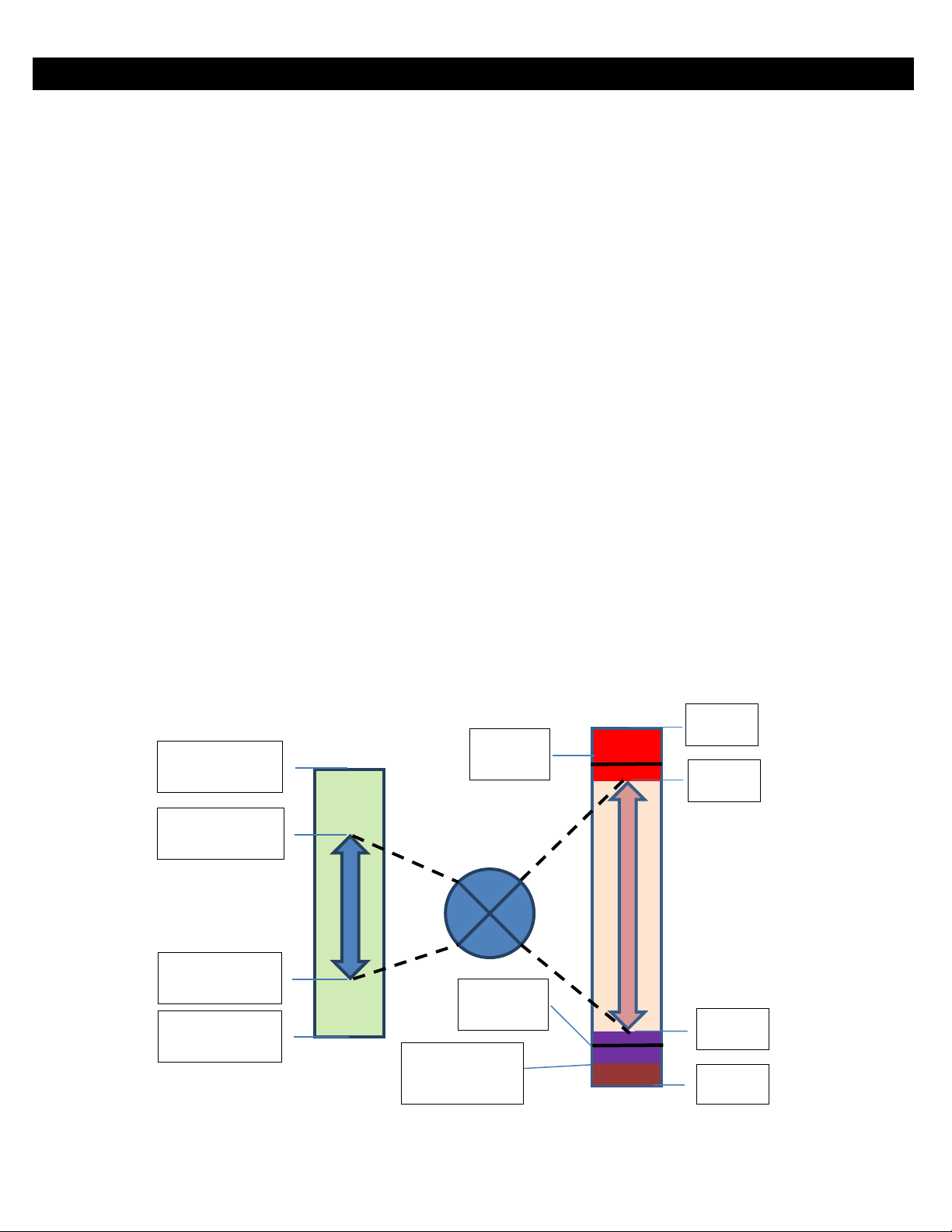
Il sensore di temperatura a morsetto HANI™ per impostazione predefinita esegue la mappatura della temperatura
misurata all'uscita di 4-20 mA. Due valori definiti dall'utente (scala minima, scala massima) definiscono l'intervallo
di temperatura mappato a 4-20 mA. Un valore misurato al di fuori dell'intervallo specificato determina una
condizione di Over-Range (Oltre l'intervallo) o Under-Range (Sotto l'intervallo). Un ripristino di fabbrica imposta la
scala minima a 0 °C e la scala massima a 100 °C.
Se il valore misurato supera la scala massima definita dall'utente, l'intervallo viene superato e l'uscita da 4-20 mA
può essere configurata per generare una corrente Fault High (Errata alta) (21,5 mA) o una corrente Fault Low
(Errata bassa) (3,8 mA). L'impostazione predefinita genera una corrente errata alta (21,5 mA).
Allo stesso modo, se il valore misurato è inferiore al valore di scala minimo definito dall'utente, il valore si trova
sotto l'intervallo e l'uscita può essere configurata per generare un'uscita errata alta o errata bassa. L'impostazione
predefinita genera una corrente errata bassa (3,8 mA).
Un errore di loop si verifica se la tensione applicata del loop da 4-20 mA scende al di sotto della tensione minima
del loop specificata e l'uscita viene portata a un livello di errore basso pari a ~ 3,38 mA.
Scala massima
(75 oC)
Scala minima
(25 oC)
Valore massimo
(100 oC)
24 mA
20 mA
4 mA
0 mA
Errata alta
(21,5 mA)
Errata bassa
(3,8 mA)
Corrente
d'esercizio minima
(3,38 mA)
Valore minimo
(100 oC)
Page 16
5.1.1 Mappatura del sensore con uscite da 4-20 mA
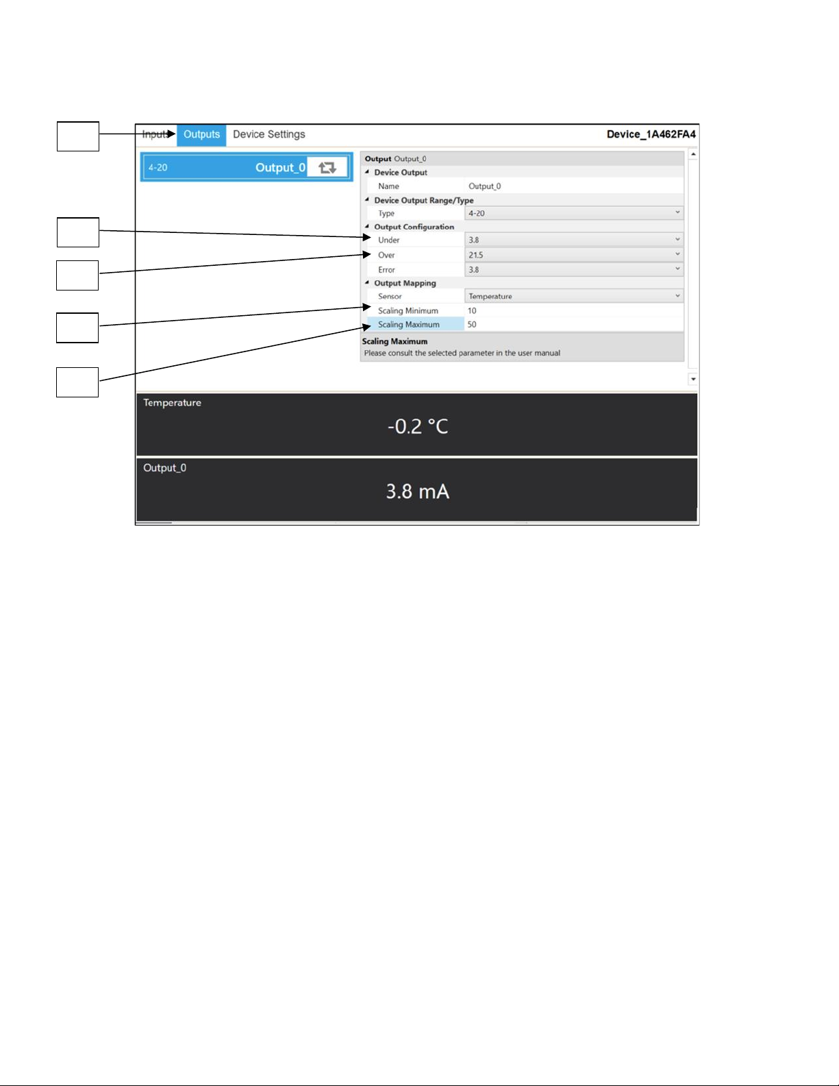
Il sensore di temperatura a morsetto HANI™ offre una mappatura del sensore di uscita a 4-20 mA. Accedere
alla scheda di configurazione Outputs [23] (Uscite) in SYNC.
Nella sezione Output Configuration (Configurazione uscita) è possibile impostare le condizioni sotto/sopra
ed errore per l'uscita analogica da 4-20 mA.
Under [24]
(Sotto):
Qualsiasi valore di temperatura inferiore al valore minimo della scala genera un errore di
valore basso.
Over [25]
(Sopra):
Qualsiasi valore di temperatura superiore al valore massimo della scala genera un errore di
valore alto.
Nella sezione Output Mapping (Mappatura uscite), è possibile impostare l'intervallo della scala dell'uscita
analogica a 4-20 mA desiderato. Il sensore di temperatura a morsetto HANI viene fornito con un intervallo di
scala delle temperature compreso tra 0 e 100 °C.
Scaling Minimum [26] (Scala
minima):
Impostare il valore della temperatura minima della scala che determinerà
un'uscita di 4 mA. In questo esempio, una temperatura di 10 °C determinerà
un'uscita analogica di 4 mA.
Scaling Maximum [27] (Scala
massima):
Impostare il valore della temperatura massima della scala che determinerà
un'uscita di 20 mA. In questo esempio, una temperatura di 50 °C determinerà
un'uscita analogica di 20 mA.
23
24
25
26
27
Page 17

6) Specifiche
POTENZA IN INGRESSO
Tensione: 8 VCC – 28 V
USCITA ANALOGICA
Corrente: 4-20 mA
PARAMETRI DI PROCESSO
Fluido di processo: acqua, liquidi a base d'acqua (altri su richiesta)
Materiali dei tubi: tubi in metallo (altro su richiesta)
Diametri esterni dei tubi:
Sanitari: 1,5", 2", 2,5”, 3”, 4”
Industriali: 1", 2", 2,5”, 3”, 4” nominali
(Altri su richiesta)
Intervallo delle temperature di processo: liquido da 0 a 100 °C, uscita analogica scalabile dall'utente
PRESTAZIONI
Precisione con fluido in scorrimento:
Tubi sanitari in metallo: ±0,5 °C
Tubi in metallo industriali: ±1,0 °C dalla fabbrica e maggiore precisione ±0,5 °C possibile con calibrazione a 1 o 2
punti in base alla situazione
(alimentazione loop)
CC
Tempo di risposta (t63): 5 secondi
Tempo di risposta (t90): 10 secondi
AMBIENTE
Temperatura ambiente di esercizio: da 0 a 40 °C (da 32 a 104 °F)
Grado di protezione: IP65 quando accoppiato
DATI MECCANICI
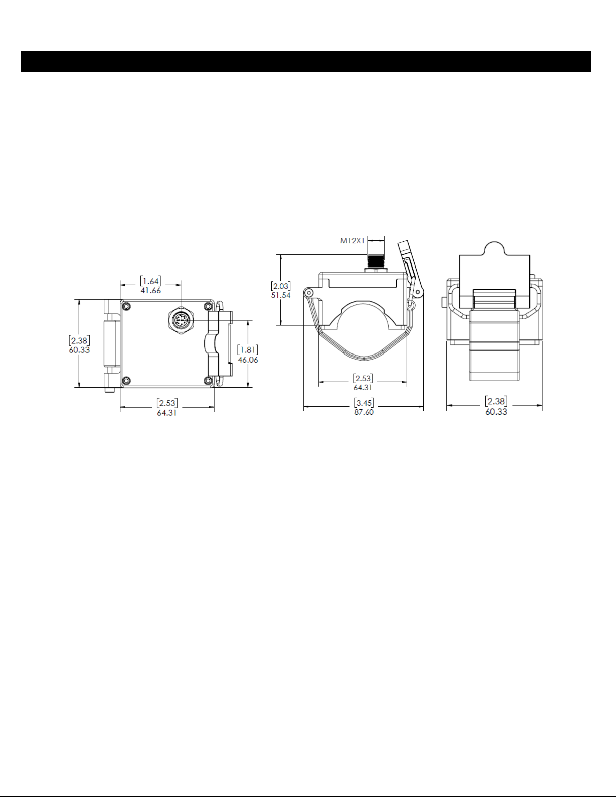
Dimensioni: 60,3 mm P x 64,31 mm L x 51,54 mm H (2,38” P x 2,53” L x 2,03” H)
Materiali: PA12, gomma siliconica, ottone nichelato, acciaio inossidabile
GENERALE
Approvazioni: CE UKCA
Page 18
7) Appendice: interfaccia di ingresso del sensore di temperatura a morsetto HANI™
7.1 Indirizzi dei registri
I dispositivi Smart Probe condividono un'architettura comune della piattaforma che offre funzionalità complete di
monitoraggio e controllo attraverso una serie di registri generici della piattaforma. È possibile accedere a questi
registri utilizzando comandi basati su I2C direttamente sui dispositivi Smart Probe o tramite una serie di registri
basati su Modbus quando si utilizzano dispositivi di interfaccia Omega. Per ulteriori informazioni, fare riferimento
al manuale dell'Interfaccia del dispositivo Smart Sensor.
All'accensione o dopo il ripristino di un dispositivo, ciascun dispositivo basato su Smart Sensor enumererà 1 o più
istanze del sensore descritte dai descrittori del sensore specifici del dispositivo, che includono opzioni di
configurazione, tipo di misurazione e unità di misura per i valori del sensore corrispondenti. Ulteriori informazioni
sul sensore sono fornite nelle descrizioni degli oggetti IPSO specifiche del sensore, che includono tipo di
misurazione esteso, precisione e tracciamento delle letture minime/massime.
Ogni sensore enumerato dispone di una posizione dell'indirizzo base del descrittore e di una posizione
dell'indirizzo della struttura IPSO/configurazione del sensore in base alla combinazione di sensori selezionata.
Sensor
e
Base descrittore
IPSO/Configurazion
e
Combinazione sensore
enumerato
Uscita digitale
4-20 mA
0
0x0060 (0xf030)
0x08a8 (0xf454)
Temperatura clamp-on
1
0x0068 (0xf034)
0x09a8 (0xf4d4)
DIO
2
0x0070 (0xf038)
0x0aa8 (0xf554)
3
0x0078 (0xf03c)
0x0ba8 (0xf5d4)
7.2 Interfaccia di ingresso del sensore di temperatura a morsetto HANI™
L'interfaccia di ingresso del sensore di temperatura a morsetto HANI™ fornisce una lettura della temperatura
calcolata in base al flusso termico misurato e ai valori di temperatura.
Nota: I sensori di temperatura a morsetto HANI™ utilizzeranno una configurazione predefinita, ma
richiederanno alcune personalizzazioni in base all'installazione specifica. Le opzioni di configurazione
saranno rese disponibili all'utente finale.
7.2.1 Descrittore ingresso sensore
Offset
Nome
Valore
Descrizione
0x00
Tipo di
misurazione
0x37
Temperatura (°C)
0x01
Tipo/formato dati
0x06
Mobile
0x02
Configurazione
0x4?
Determina il tipo di materiale
0x03
Dispositivo
sensore
0x??
Determina il tipo di connessione
0x04..0x08
UOMR
“°C”
Unità di misura
7.2.1.1 Tipo di misurazione del sensore
L'interfaccia della temperatura consente di misurare la temperatura in °C.
Tipo di
sensore
Unità
derivate SI
Misurazione
0x37
°C
Temperatura
Page 19
7.2.1.2 Tipo/formato dati ingresso sensore
Il sensore di temperatura a morsetto HANI™ supporta una configurazione estesa e fornisce la
calibrazione di fabbrica. Tutti i valori dei dati vengono restituiti come valori a virgola mobile a 32 bit.
Tipo/formato dati in ingresso del sensore di temperatura a morsetto HANI™
7 6 5 4 3 2 1
0
Sensori
smart
Scrivibile
Calibrazione
di fabbrica
Riservato
Tipo di dati
0 0 0
0
0x06 == FLOAT
7.2.1.2.1 Tipo di dati
Il campo 4-bit Data Type (Tipo dati a 4 bit) determina il tipo di dati del sensore specifico.
7.2.1.2.2 Calibrazione di fabbrica
È disponibile la calibrazione di fabbrica per gli ingressi del processo del sensore di temperatura a
morsetto HANI™. L'eliminazione di questo bit disattiva i valori di calibrazione di fabbrica.
7.2.1.2.3 Scrivibile
Il bit scrivibile viene cancellato, indicando che i valori del sensore potrebbero non essere
sovrascritti.
7.2.1.3 Byte di configurazione del sensore
Byte di configurazione del sensore di temperatura a morsetto HANI™
7 6 5 4 3 2 1
0
Disponibile
Assegnato
Applicare
la scala
Blocco
Intervallo/tipo sensore
0 * ?
?
Materiale (vedere sotto)
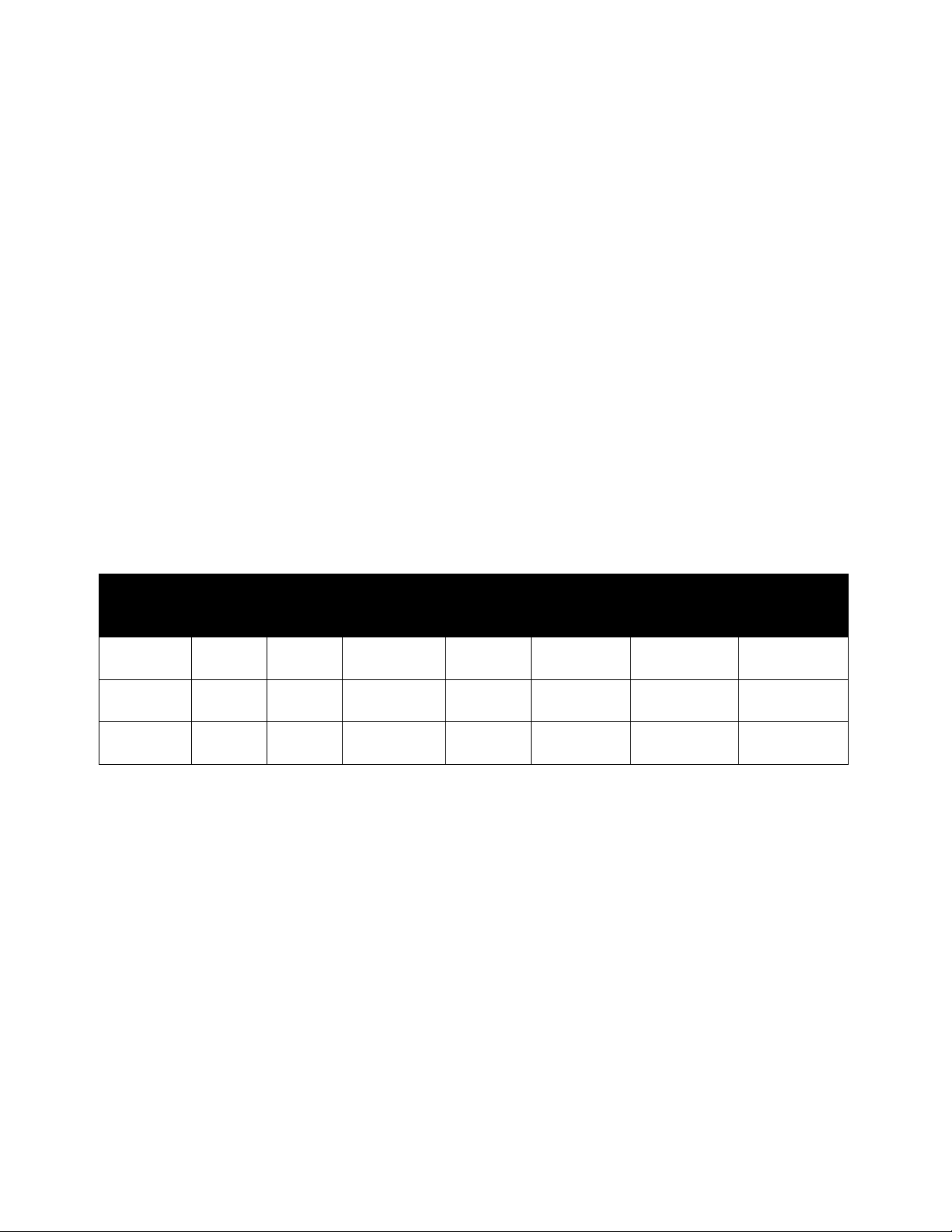
7.2.1.3.1 Intervallo/tipo sensore
Il campo Range/Type (Intervallo/Tipo) determina il tipo di materiale del tubo, che determina la
conduttività termica.
Se si seleziona User Specified (Specificato dall'utente), la conduttività può essere selezionata come
parametro del sensore (vedere di seguito).
Intervallo/Tipo
Materiale
DESCRIZIONE
Conduttività
(W/m-K)
0x00
Specificato
dall'utente
--
4,0
0x01
SS
Acciaio inox
13
0x02
CS
Acciaio al carbonio
40
0x03
GS
Acciaio zincato
40
0x04
CU
Rame
401
0x05
BR
Ottone
111
0x06
AL
Alluminio
236
0x07
0x08
0x09
0x0a
0x0b
0x0c
0x0d
0x0e
0x0f
Page 20
7.2.1.3.2 Blocco
Se impostato, verrà utilizzata la stringa di unità di misura specificata dall'utente (massimo 4
caratteri) al posto delle unità di misura predefinite.
7.2.1.3.3 Applicare la scala
Se impostato, i valori di offset e guadagno definiti dall'utente verranno utilizzati per regolare la
lettura del sensore:
Risultato = (lettura non elaborata * guadagno) + Offset
7.2.1.3.4 Assegnato
Il bit Assigned (Assegnato) sarà sempre uguale a 0. Per ulteriori informazioni, fare riferimento al
manuale dell'Interfaccia del dispositivo Smart Sensor.
7.2.1.3.5 Disponibile
Il bit Available (Disponibile) sarà sempre uguale a 0. Per ulteriori informazioni, fare riferimento al
manuale dell'Interfaccia del dispositivo Smart Sensor.
7.2.1.4 Byte dispositivo sensore
Il byte del dispositivo sensore di temperatura a morsetto HANI™ non viene utilizzato.
7.2.2 Parametri di temperatura del sensore
Il sensore di temperatura a morsetto HANI™ fornisce 3 parametri del sensore che possono essere aggiornati
in base all'installazione specifica.
I parametri del sensore di temperatura a morsetto HANI™ sono accessibili quando il dispositivo si trova in
modalità di funzionamento normale (vedere funzione di attivazione IPSO).
Parametro
Registro
I2C
Registro
Modbus
Nome
Intervallo
Incremento
Ripristino
impostazioni
di fabbrica
Descrizione
0
0x08c0
0xf460
Diametro
25,4 -
76,2
0,1
38,1
Diametro in
mm
1
0x08d0
0xf468
Spessore
1,0 - 10,0
0,1
1,7
Spessore in
mm
2
0x08e0
0xf470
Conduttività
0,01-500
0,01
4
Conduttività
in W/m-K
7.2.2.1 Diametro
Il diametro viene utilizzato nel calcolo della temperatura ed è un fattore specifico dell'installazione.
7.2.2.2 Spessore
Lo spessore viene utilizzato nel calcolo della temperatura ed è un fattore specifico dell'installazione.
7.2.2.3 Conduttività
La conduttività viene fornita in W/m-K e viene utilizzata nel calcolo della temperatura. Il parametro
Conductivity (Conduttività) è visibile solo se la selezione del materiale è User Specified (Specificata
dall'utente).
Page 21
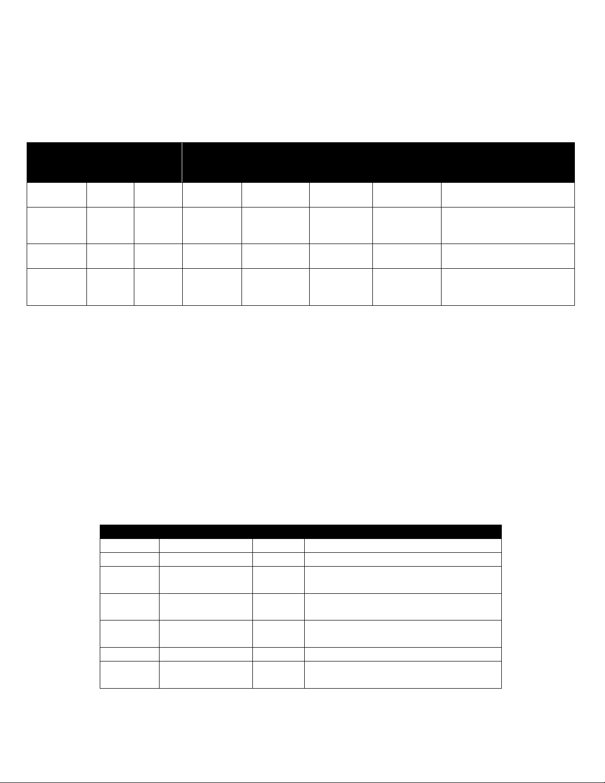
7.2.3 Parametri di calibrazione del sensore definiti dall'utente
Il sensore di temperatura a morsetto HANI™ consente all'utente di eseguire una calibrazione a singolo o
doppio punto.
I parametri del sensore di temperatura a morsetto HANI™ sono accessibili quando il dispositivo si trova in
modalità Calibration (Calibrazione) (vedere funzione di attivazione IPSO). Il valore di calibrazione viene
calcolato internamente durante la sequenza di calibrazione utente e non è accessibile dall'esterno.
Parametro
Registro
I2C
Registro
Modbus
Nome
Intervallo
Incremento
Ripristino
impostazioni
di fabbrica
Descrizione
0
0x08c0
0xf460
Lettura
bassa
0,0 - 100,0
0,1
0,0
Valore letto dal sensore
HANI™
1
0x08d0
0xf468
Low Actual
(Effettivo
basso)
0,0 - 100,0
0,1
0,0
Valore effettivo misurato.
2
0x08e0
0xf470
Lettura alta
0,0 - 100,0
0,1
100,0
Valore letto dal sensore
HANI™
3
0x08f0
0xf478
High Actual
(Effettivo
alto)
0,0 - 100,0
0,1
100,0
Valore effettivo misurato.
7.2.3.1 Lettura bassa
Il valore della temperatura viene letto dal sensore HANI.
7.2.3.2 Low Actual (Effettivo basso)
La temperatura bassa effettiva misurata da un sensore esterno indipendente.
7.2.3.3 Lettura alta
Il valore della temperatura viene letto dal sensore HANI.
7.2.3.4 High Actual (Effettivo alto)
La temperatura alta effettiva misurata da un sensore esterno indipendente.
7.2.4 Definizione IPSO del sensore
La definizione IPSO del sensore di temperatura a morsetto HANI™ fornisce informazioni relative a intervallo
del segnale, valori min/max misurati e tipo di oggetto IPSO. Le informazioni sull'intervallo dipendono dal tipo
di temperatura.
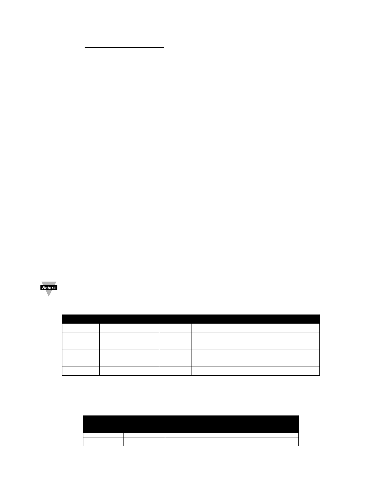
Offset
Nome
Valore
Descrizione
0xa8
Tipo di sensore
3303
Temperatura (°C)
0xaa
Precisione
1
Fornisce la lettura di xxx.x
0xac
Attivazione del
sensore
??
(vedere di seguito)
0xb0
Valore min.
misurato
??
Valore minimo dall'ultimo ripristino
0xb4
Valore massimo
misurato
??
Valore massimo dall'ultimo azzeramento
0xb8
Intervallo minimo
0
Temperatura minima
0xbc
Intervallo
massima
100
Temperatura massima
7.2.4.1 Precisione
Il valore della temperatura misurata viene arrotondato per fornire una risoluzione di ±0,1 gradi.
Page 22
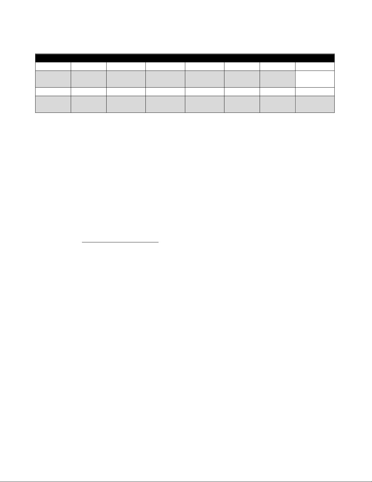
7.2.4.2 Attivazione del sensore
La funzione di attivazione del sensore viene utilizzata per ripristinare i valori min/max IPSO e per
controllare il processo di calibrazione.
Attivazione del sensore
7 6 5 4 3 2 1
0
0 0 0 0 0 0 0
Ripristino
min/max
15
14
13
12
11
10 9 8
0 0 Reset
calibrazione
Stato
calibrazione
Modalità di
calibrazione
Acquis.
alto
Acquis.
basso
Avvio
calibrazione
Impostando il bit di ripristino min/max su 1, verranno ripristinati i valori min/max registrati dal processo
IPSO.
7.2.4.2.1 Sequenza di calibrazione utente
User Calibration (Calibrazione utente) consente all'utente di regolare i piccoli errori fornendo un
offset (calibrazione a punto singolo) o un offset e un guadagno (calibrazione a doppio punto)
rispetto al valore di temperatura misurato. Per impostare il valore di correzione è possibile
utilizzare la sequenza seguente:
1. Scrivere 0x0800 nel registro delle funzioni di attivazione (set di bit della modalità di
calibrazione). In questo modo, il dispositivo viene impostato in modalità di calibrazione e
l'accesso al registro dei parametri del sensore viene sostituito dall'accesso al registro di
calibrazione del sensore.
Calibrazione a doppio punto
2. Applicare una temperatura di fluido nota vicino all'estremità inferiore dell'intervallo di
temperatura previsto e inserirla nel registro Low Actual (Effettivo basso) (0x08c4/0xf462).
3. Registrare il valore misurato dal sensore HANI e inserirlo nel registro di lettura inferiore
(0x08c0/0xf460). Questo processo può essere semplificato scrivendo un valore di 0x0a00 nel
registro della funzione di attivazione, in modo che il sensore HANI acquisisca la lettura
corrente e la salvi come valore di lettura basso.
4. Applicare una temperatura di fluido nota vicino all'estremità superiore dell'intervallo di
temperatura previsto e inserirla nel registro High Actual (Effettivo alto) (0x08cc/0xf466).
5. Registrare il valore misurato dal sensore HANI e inserirlo nel registro di lettura superiore
(0x08c8/0xf464). Questo processo può essere semplificato scrivendo un valore di 0x0c00 nel
registro della funzione di attivazione, in modo che il sensore HANI acquisisca la lettura
corrente e la salvi come valore di lettura alto.
6. Scrivere 0x0900 nel registro delle funzioni di attivazione (modalità calibrazione e avvio
calibrazione). All'interno, il dispositivo imposta il bit Calibration Status (Stato calibrazione) e
calcola i valori di linearizzazione Gain (Guadagno) e Offset. Una volta completato il calcolo
della calibrazione, il bit dello stato di calibrazione viene cancellato.
7. Scrivere 0x0000 nel registro delle funzioni di attivazione per riportare il dispositivo alla
modalità di funzionamento normale.
Page 23
Calibrazione a punto singolo
8. Applicare una temperatura di fluido nota vicino al centro dell'intervallo di temperatura
previsto e inserirla nel registro Low Actual (Effettivo basso) (0x08c4/0xf462).
9. Registrare il valore misurato dal sensore HANI e inserirlo nel registro di lettura inferiore
(0x08c0/0xf460). Questo processo può essere semplificato scrivendo un valore di 0x0a00 nel
registro della funzione di attivazione, in modo che il sensore HANI acquisisca la lettura
corrente e la salvi come valore di lettura basso.
10. Scrivere lo stesso valore del punto 8 nel registro High Actual (Effettivo alto) (0x08cc/0xf466).
11. Scrivere 0x0900 nel registro delle funzioni di attivazione (modalità calibrazione e avvio
calibrazione). All'interno, il dispositivo imposta il bit Calibration Status (Stato calibrazione) e
calcola il valore di offset. Una volta completato il calcolo della calibrazione, il bit dello stato di
calibrazione viene cancellato.
Scrivere 0x0000 nel registro delle funzioni di attivazione per riportare il dispositivo alla modalità
di funzionamento normale.
Il valore di correzione può essere azzerato scrivendo 0x2800 (reset calibrazione e modalità
calibrazione) nel registro delle funzioni di attivazione.
7.3 Interfaccia DIO
L'opzione Digital output (Uscita digitale) supporta un'interfaccia DIO che fornisce 2 ingressi digitali cablati alle
uscite digitali. Questi possono essere utilizzati per rilevare lo stato degli interruttori esterni (uscita disattivata) o
per monitorare lo stato delle uscite.
Nota: l'interfaccia DIO non è disponibile per le unità configurate con uscite da 4-20 mA.
7.3.1 Descrittore DIO
Offset
Nome
Valore
Descrizione
0x00
Tipo di sensore
0x18
Tipo digitale (mappatura bit)
0x01
Tipo/formato dati
0x46
Configurabile, tipo mobile
0x02
Configurazione
0x23
Scala applicata, bit 0 e 1 attivati
0x03
Dispositivo
sensore
0x0f
Bit DIN abilitati/invertiti
0x04
UOMR
"DIN"
Unità di misura
7.3.1.1 Tipo di sensore DIO
L'interfaccia fornisce un ingresso con mappatura bit delle 2 linee di segnale digitale.
Tipo di
sensore
Unità
derivate SI
Misurazione
0x18
DIN
Ingressi digitali con mappatura bit
Page 24
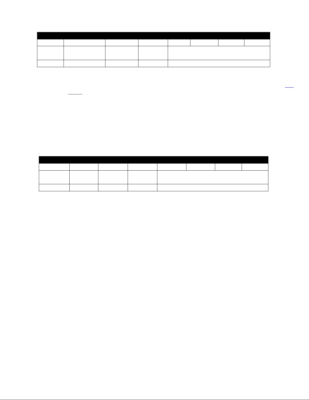
7.3.1.2 Tipo/formato dati DIO
Tipo/formato dati DIO
7 6 5 4 3 2 1
0
Sensori
smart
Scrivibile
Calibrazione
di fabbrica
riservato
Tipo di dati
0 0 0
0
6 == virgola mobile
7.3.1.2.1 Tipo di dati
Il campo 4-bit Data Type (Tipo dati a 4 bit) determina il tipo di dati del sensore specifico (vedere Tipi
di dati).
7.3.1.2.2 Calibrazione di fabbrica
Il bit di calibrazione di fabbrica non viene utilizzato per i tipi DIO.
7.3.1.2.3 Scrivibile
Indica che il valore del sensore può essere sovrascritto. Non utilizzato su ingressi DIO.
7.3.1.2.4 Sensori smart
Fare riferimento alla documentazione dell'Interfaccia del dispositivo Smart Sensor.
7.3.1.3 Configurazione ingresso DIO
Configurazione ingresso DIO
7 6 5 4 3 2 1
0
Disponibile
Assegnato
Applicare
la scala
Blocco
Selezione sottocanale
0 0 1
?
0x03 == bit 0 e 1
7.3.1.3.1 Blocco
Se impostato, verrà utilizzata la stringa di unità di misura specificata dall'utente (massimo 4
caratteri) al posto del DIN predefinito.
7.3.1.3.2 Applicare la scala
Se impostato, i valori di offset e guadagno definiti dall'utente verranno utilizzati per regolare la
lettura del sensore:
Risultato = (lettura non elaborata * guadagno) + Offset
7.3.1.3.3 Assegnato
Il bit Assigned (Assegnato) sarà sempre uguale a 0. Per ulteriori informazioni, fare riferimento al
manuale dell'Interfaccia del dispositivo Smart Sensor.
7.3.1.3.4 Disponibile
Il bit Available (Disponibile) sarà sempre uguale a 0. Per ulteriori informazioni, fare riferimento al
manuale dell'Interfaccia del dispositivo Smart Sensor.
Page 25
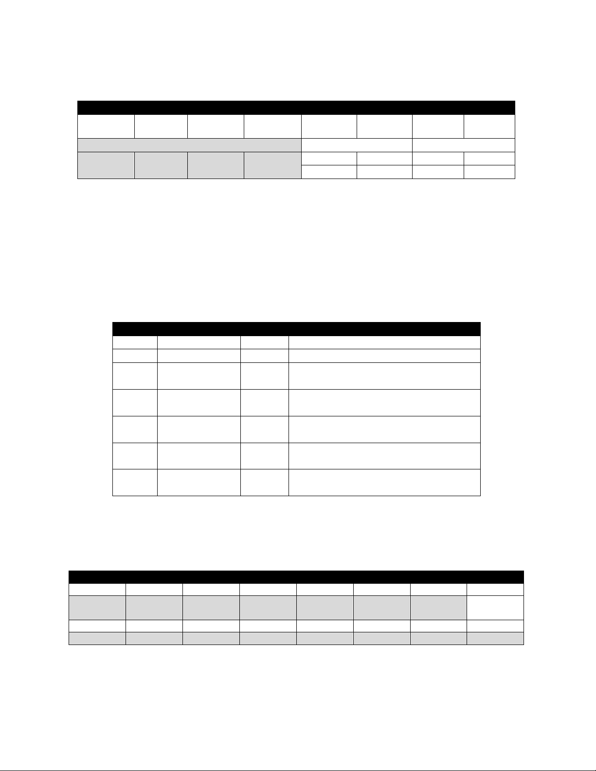
7.3.1.4 Configurazione del dispositivo DIO
La configurazione del dispositivo DIO consente di abilitare ciascuno dei 2 bit di ingresso e di selezionare
se l'ingresso è attivo ALTO (valore 1 quando l'ingresso non è collegato a massa) o attivo BASSO (valore 1
quando l'ingresso è collegato a massa).
Configurazione del dispositivo DIO
7 6 5 4 3 2 1
0
Riservato
DIN 1
DIN 0
0 0 0
0
ABIL.
INVERT.
ABIL.
INVERT.
1 1 1
1
7.3.1.4.1 Inversione
Se è impostato il bit di inversione, l'ingresso è attivo BASSO.
7.3.1.4.2 Abilitazione
Se è impostato il bit di abilitazione, l'ingresso è abilitato.
7.3.2 Definizione IPSO di DIO
La definizione IPSO dell'ingresso DIO fornisce informazioni relative a intervallo del segnale, valori min/max
misurati e tipo di oggetto IPSO.
Offset
Nome
Valore
Descrizione
0xa8
Tipo di sensore
3349
Mappatura bit digitale
0xaa
Precisione
0
Fornisce la lettura di xxx
0xac
Attivazione del
sensore
??
Scrivendo 0x0001 si forza il ripristino di
min/max
0xb0
Valore min.
misurato
??
Valore minimo dall'ultimo ripristino
0xb4
Valore massimo
misurato
??
Valore massimo dall'ultimo azzeramento
0xb8
Intervallo
minimo
0
Lettura minima
0xbc
Intervallo
massima
3
Lettura massima
7.3.2.1 Funzione di attivazione del sensore
La funzione di attivazione del sensore viene utilizzata per ripristinare i valori min/max IPSO e per
controllare il processo di calibrazione.
Funzione di attivazione del sensore
7 6 5 4 3 2 1
0
0 0 0 0 0 0 0
Ripristino
min/max
15
14
13
12
11
10 9 8 0 0 0 0 0 0 0 0
Impostando il bit di ripristino min/max su 1, verranno ripristinati i valori min/max registrati dal processo
IPSO.
Gli ingressi DIO non supportano il processo di calibrazione dell'utente e tutti i bit di configurazione
devono essere scritti come 0.
Page 26
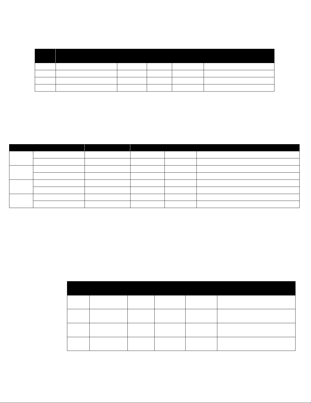
7.4 Registri di configurazione delle uscite
Le uscite condividono una struttura comune costituita da 3 campi mappati a un numero intero non firmato a
16 bit, accessibile nella mappa del registro del sensore Smart.
Uscita
Nome
Indirizzo
Modbus
Indirizzo
I2C
Dimensioni
Descrizione tipica
0
Descrittore uscita 0
0xf09a
0x0134
uint16
PWM 0 o 4-20 mA
1
Descrittore uscita 1
0xf09b
0x0136
uint16
PWM 1 (vedere di seguito)
2
Descrittore uscita 2
0xf09c
0x0138
uint16
Phantom (non configurabile)
3
Descrittore uscita 3
0xf09d
0x013a
uint16
Phantom (non configurabile)
Per ulteriori informazioni, fare riferimento al tipo di uscita specifico.
7.4.1 Scala valori minimo/massimo
Quando si utilizza la mappatura del sensore, l'utente può specificare l'intervallo del segnale di ingresso
attraverso i parametri di scala minima e scala massima. È presente una coppia di registri per ciascuna delle 4
uscite possibili.
Sensore
Nome
Indirizzo Modbus
Indirizzo I2C
Dimensioni
Descrizione
0
Scala bassa uscita 0
0xf1f0
0x03e0
mobile
Imposta un intervallo di ingresso inferiore
Scala alta uscita 0
0xf1f2
0x03e4
mobile
Imposta un intervallo di ingresso superiore
1
Scala bassa uscita 1
0xf1f4
0x03e8
mobile
Imposta un intervallo di ingresso inferiore
Scala alta uscita 1
0xf1f6
0x03ec
mobile
Imposta un intervallo di ingresso superiore
2
Scala bassa uscita 2
0xf1f8
0x03f0
mobile
Imposta un intervallo di ingresso inferiore
Scala alta uscita 2
0xf1fa
0x03f4
mobile
Imposta un intervallo di ingresso superiore
3
Scala bassa uscita 3
0xf1fc
0x03f8
mobile
Imposta un intervallo di ingresso inferiore
Scala alta uscita 3
0xf1f2e
0x03fc
mobile
Imposta un intervallo di ingresso superiore
Quando cambia il valore della scala bassa o della scala alta, viene eseguito un calcolo interno per calcolare la
trasformazione lineare da applicare alla lettura del sensore.
7.4.2 Valori di uscita
Le uscite utilizzano valori mobili che rappresentano la percentuale di fondo scala. Se l'uscita non è mappata,
il valore scritto (0 – 100%) è identico al valore restituito.
Se l'uscita è mappata, i valori di scala vengono utilizzati per trasformare il valore di ingresso minimo in 0% e il
valore di ingresso massimo in 100% (vedere Scala del sensore).
Uscita
Nome
Indirizzo
Modbus
Indirizzo
I2C
Dimensioni
Descrizione
0
Valore uscita
0
0xf078
0x00f0
mobile
Percentuale del valore di fondo
scala (0-100%)
1
Valore uscita
1
0xf07a
0x00f4
mobile
Percentuale del valore di fondo
scala (0-100%)
2
Valore uscita
2
0xf07c
0x00f8
mobile
Percentuale del valore di fondo
scala (0-100%)
3
Valore uscita
3
0xf07e
0x00fc
mobile
Percentuale del valore di fondo
scala (0-100%)
Page 27
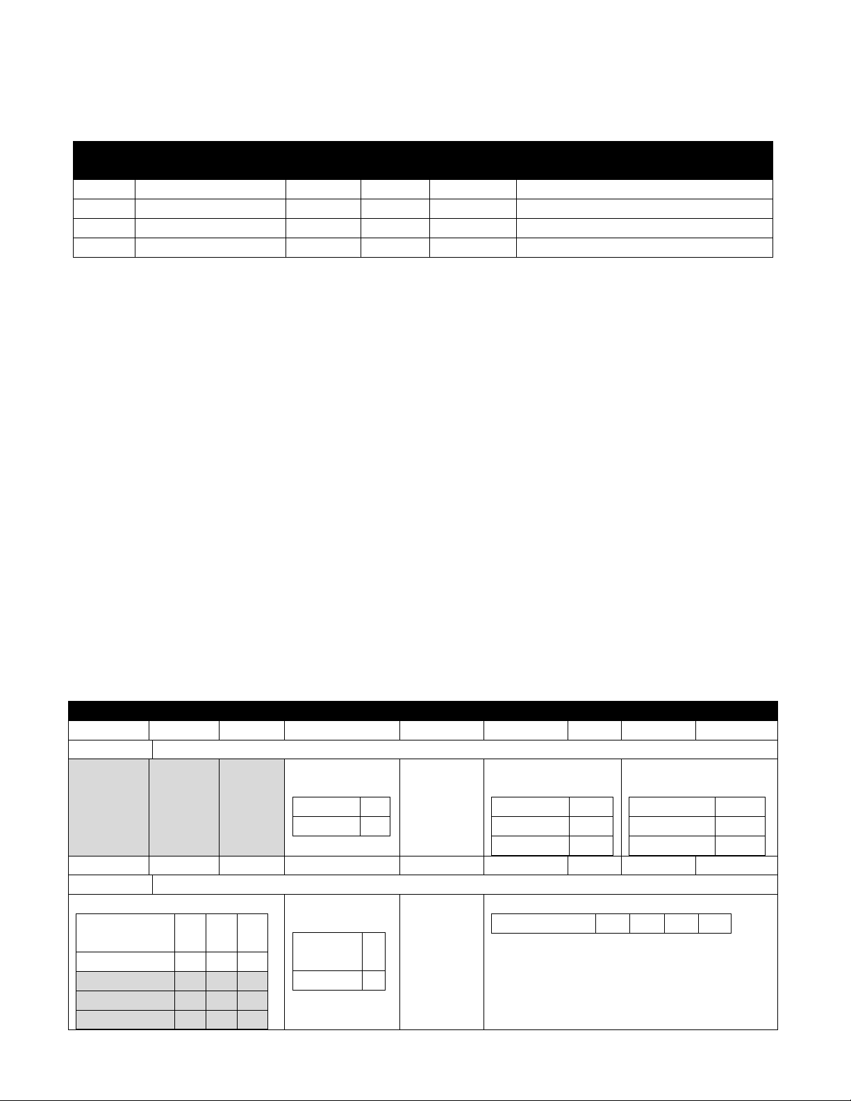
7.4.3 Nomi delle uscite
Ogni uscita ha un nome. I nomi predefiniti per le uscite sono compresi tra Output_0 e Output_3. I nomi
predefiniti possono essere sovrascritti, ad esempio “Stack_Lite” (Torretta luminosa) o ‘Control_Valve'
(Valvola di controllo). I nomi sono limitati a 16 caratteri.
Uscita
Nome
Indirizzo
Modbus
Indirizzo
I2C
Dimensioni
Descrizione
0
Nome uscita 0
0xf078
0xf720
caratt.[16]
L'impostazione predefinita è Output_0
1
Nome uscita 1
0xf07a
0xf728
caratt.[16]
L'impostazione predefinita è Output_1
2
Nome uscita 2
0xf07c
0xf730
caratt.[16]
L'impostazione predefinita è Output_2
3
Nome uscita 3
0xf07e
0xf738
caratt.[16]
L'impostazione predefinita è Output_3
I nomi delle uscite vengono conservati fino al ripristino delle impostazioni di fabbrica.
Tenere ben presente quanto segue:
1. Gli spazi all'interno del nome devono essere sostituiti dal carattere “_”.
2. Tutti i nomi delle uscite su un particolare dispositivo sono univoci: se sono supportate funzioni
duplicate, aggiungere una stringa ‘_x', dove x rappresenta l'istanza. Ad esempio, utilizzare Stack_Lite_1
e Stack_Lite_2 se vengono collegate 2 torrette luminose.
7.5 Configurazione dell'uscita da 4-20 mA
Le uscite da 4-20 mA sono ampiamente utilizzate grazie ai numerosi vantaggi delle uscite di sovratensione:
1. Maggiore immunità ai disturbi
2. Capacità di alimentare il dispositivo di rilevamento utilizzando la corrente di misurazione: la potenza totale
fornita è inferiore a ~3,5 mA X tensione di loop minima.
3. Rilevamento automatico interruzione fili: se i fili del segnale vengono interrotti, la corrente scende a 0 mA,
consentendo al sistema di controllo di rilevare il guasto.
4. Rilevamento automatico fili in cortocircuito: se i fili del segnale sono in cortocircuito, la corrente supera il
valore di 20 mA specificato, consentendo al sistema di controllo di rilevare il guasto.
Il dispositivo con alimentazione loop da 4-20 mA del sensore di temperatura a morsetto HANI™ richiede una
tensione di loop minima di 8,0 volt, consentendo l'alimentazione del dispositivo mediante segnali di controllo
convenzionali da 4-20 mA. La configurazione predefinita di fabbrica collega la temperatura misurata al segnale di
uscita da 4-20 mA.
Configurazione dell'uscita da 4-20 mA
7 6 5 4 3 2 1 0
Configurazione uscita
0 0 0
Errore di
sistema
3,8 mA
0
21,5 mA
1
Errore intervallo
alto
3,8 mA
0
21,5 mA
1
Pass-thru
2 (3)
Errore intervallo
basso
3,8 mA
0
21,5 mA
1
Pass-thru
2 (3) 15
14
13
12
11
10 9 8
Tipo di uscita
Mappatura del sensore
Nessuna
mappatura
0 - -
Sensore 0
1 0 0
Sensore 1
1 0 1
Sensore 2
1 1 0
Sensore 3
1 1 1
Mappatura
abilitata
Non
abilitata
0
Abilitata
1
Tipo di uscita
4-20 mA
0 1 0
0
Page 28
7.5.1 Intervallo alto/intervallo basso
I valori di configurazione intervallo alto e intervallo basso determinano quale segnale da 4-20 mA viene
generato se il segnale è superiore o inferiore all'intervallo di ingresso specificato. L'opzione pass-thru indica
che il segnale di uscita non è bloccato.
Se il valore misurato supera il valore massimo dell'ingresso definito dall'utente, si verifica una condizione di
Over-Range (Oltre l'intervallo). L'uscita da 4-20 mA può essere configurata per generare una corrente errata
alta (21,5 mA) o una corrente di errata bassa (3,8 mA) quando si verifica una condizione che supera
l'intervallo.
Allo stesso modo, se il valore misurato è inferiore al valore minimo definito dall'utente, si verifica una
condizione Under-Range (Sotto l'intervallo) e l'uscita può essere configurata per generare un'uscita errata
alta o errata bassa.
Un errore di loop si verifica se la tensione applicata del loop da 4-20 mA scende al di sotto della tensione
minima del loop specificata e l'uscita viene portata a un livello di errore basso pari a ~3,5 mA.
7.5.2 Errore di sistema
L'impostazione di System Error (Errore di sistema) definisce se l'uscita viene portata a una corrente bassa o
alta nel caso in cui si verifichi un errore di sistema interno.
7.5.3 Tipo di uscita
Il tipo di uscita è impostato all'uscita di 4-20 mA.
7.5.4 Mappatura abilitata
Se impostata, il bit Mapping Enabled (Mappatura abilitata) di sola lettura indica che l'uscita può essere
facoltativamente mappata direttamente su un ingresso del sensore. Se il bit con mappatura abilitata è vuoto,
significa che non è supportata alcuna mappatura e il campo Sensor Mapping (Mappatura sensore) viene
ignorato.
7.5.5 Mappatura delle uscite
Il valore Output Mapping (Mappatura uscite) può essere impostato a “no mapping” (nessuna mappatura) o
“Sensor 0 through 3” (Sensore da 0 a 3). Se non viene selezionata alcuna mappatura, l'uscita da 4-20 mA può
essere controllata direttamente scrivendo un valore compreso tra 0 e 100% (da 0 mA a 24 mA) in
corrispondenza del valore di uscita interno. Se si seleziona un sensore, l'uscita da 4-20 mA verrà scalata per
tenere traccia del valore del sensore misurato tra l'intervallo di scala bassa e scala alta.
Se non è presente alcuna mappatura del sensore, il valore dell'uscita uscita viene determinato dalla
percentuale di attivazione applicata (0–100%). Ad esempio, un'eccitazione al 50% genera una corrente di
uscita di 12 mA, mentre un'attivazione al 75% genera un'uscita di (75/100) * 24 mA == 18 mA.
7.5.6 Scala valori minimi/massimi
Quando si utilizza la mappatura del sensore con l'uscita da 4-20 mA, l'utente può specificare l'intervallo del
segnale di ingresso attraverso i parametri di scala minima e scala massima.
Nome
Indirizzo Modbus
Indirizzo I2C
Dimensioni
Descrizione
Scala minima
0xf1f0
0x03e0
mobile
Imposta un intervallo di ingresso inferiore
Scala massima
0xf1f2
0x03e4
mobile
Imposta un intervallo di ingresso superiore
Nota: a causa dei requisiti di alimentazione loop che specificano un'uscita, un valore inferiore al 15%
(3,5 mA) viene generalmente fissato a 3,6 mA.
7.5.7 Errore alimentazione loop di 4-20 mA
Un errore di loop si verifica se la tensione applicata del loop da 4-20 mA scende al di sotto della tensione
minima del loop specificata e l'uscita viene portata a un livello di errore basso pari a ~3,5 mA.
Page 29
7.6 Configurazione dell'uscita digitale
L'opzione Digital output (Uscita digitale) fornisce due segnali di uscita che possono essere configurati per le uscite
ON/OFF, PWM o SERVO tramite i registri di configurazione delle uscite. Le uscite rimanenti vengono assegnate
come dispositivi phantom non configurabili.
Le voci evidenziate mostrano le configurazioni predefinite tipiche.
Configurazione dell'uscita digitale
7 6 5
4
3 2 1 0
Configurazione uscita
Intervallo
servo
1,0 - 2,0
0
0,5 - 2,5
1
Stato attivo
BASSO
0
ALTO
1
Frequenza
100 Hz
0 0 0
10 Hz
0 0 1
1 Hz
0 1 0
0,1 Hz
0 1 1
50 Hz
1 0 0
33 Hz
1 0 1
25 Hz
1 1 0
20 Hz
1 1 1
15
14
13
12
11 10 9 8
Tipo di uscita
Mappatura del sensore
Nessuna
mappatura
0 - -
Sensore 0
1 0 0
Sensore 1
1 0 1
Sensore 2
1 1 0
Sensore 3
1 1 1
Mappatura
abilitata
Non
abilitata
0
Abilitata
1
Tipo di uscita
Nullo
0 0 0 0 ON/OFF
0 0 0 1 PWM
0 0 1 0 Servo
0 0 1
1
7.6.1 Frequenza
La velocità determina la velocità di ripetizione o la velocità dell'uscita digitale. Per le uscite On/Off, il campo
della velocità viene ignorato.
7.6.1.1 Velocità PWM
L'uscita digitale supporta le seguenti frequenze PWM:
Velocità
PWM
Nome
Descrizione
0
100 Hz
Il segnale PWM ha una frequenza costante di 100 Hertz (velocità di
ripetizione 10 msec) con un ciclo di lavoro compreso tra 0 e 100%
1
10 Hz
Il segnale PWM ha una frequenza costante di 10 Hertz (velocità di
ripetizione 100 msec) con un ciclo di lavoro compreso tra 0 e 100%
2
1 Hz
Il segnale PWM ha una frequenza costante di 1 Hertz (velocità di
ripetizione 1 sec) con un ciclo di lavoro compreso tra 0 e 100%
3
0,1 Hz
Il segnale PWM ha una frequenza costante di 0,1 Hertz (velocità di
ripetizione 10 sec) con un ciclo di lavoro compreso tra 0 e 100%
Page 30
7.6.1.2 Frequenza SERVO
Le sonde Smart Sensor supportano le seguenti frequenze SERVO:
Velocità
PWM
Nome
Descrizione
0
100 Hz
Il segnale PWM ha una frequenza costante di 100 Hertz (velocità di
ripetizione 10 msec) con un ciclo di lavoro compreso tra 0 e 100%
4
50 Hz
Il segnale PWM ha una frequenza costante di 50 Hertz (velocità di
ripetizione 20 msec) con un ciclo di lavoro compreso tra 0 e 100%
7.6.2 Tipo di uscita
Le sonde Smart Sensor supportano le uscite NULL (0), ON/OFF (1), PWM (2) e SERVO (3). Se impostato su
NULL, il segnale di uscita rimane in uno stato di impedenza elevata. Se impostati su ON/OFF, i comandi della
frequenza e dell'intervallo servo non hanno alcun effetto. Quando si seleziona il tipo SERVO, il ciclo di lavoro
è limitato quindi il segnale di uscita corrisponde a
0,5-2,5 msec o 1,0-2,0 msec in base al bit dell'intervallo servo.
7.6.3 Stato attivo
Le uscite digitali del sensore Smart possono essere configurate come attive ALTE o attive BASSE. Quando è
impostata su 1 (attivo alto), l'uscita sarà ad alta impedenza quando è attiva. Quando è impostata su 0 (attivo
basso), l'uscita sarà a bassa impedenza (~0,0 volt) quando è attiva. Il valore di ripristino delle impostazioni di
fabbrica è 0 (basso).
7.6.4 Mappatura abilitata
Il bit Mapping Enabled (Mappatura abilitata) di sola lettura indica che l'uscita può essere facoltativamente
mappata direttamente su un ingresso del sensore in base al campo Sensor Mapping (Mappatura sensore). Se
il bit con mappatura abilitata è vuoto, significa che non è supportata alcuna mappatura e il campo Sensor
Mapping (Mappatura sensore) viene ignorato.
7.6.5 Mappatura delle uscite
Il valore Output Mapping (Mappatura uscite) può essere impostato a “no mapping” (nessuna mappatura) o
“Sensor 0..3” (Sensore da 0 a 3). Se non viene selezionata alcuna mappatura, l'uscita può essere controllata
direttamente scrivendo un valore compreso tra 0 e 100% in corrispondenza del valore di uscita interno. Se
viene selezionato un sensore e l'hardware supporta la mappatura, l'uscita tiene traccia del valore del sensore
selezionato, scalato in base ai valori minimo e massimo dell'uscita.
Se la mappatura dell'uscita è abilitata per le uscite PWM, vengono utilizzati i valori di scala in modo che un
ingresso del segnale in corrispondenza o al di sotto del valore di scala basso generi un'uscita pari a 0% e un
ingresso del segnale in corrispondenza o al di sopra del valore di scala alto generi un ciclo di lavoro PWM pari
a 100%.
Se la mappatura dell'uscita è abilitata per le uscite SERVO, vengono utilizzati i valori di scala in modo che un
ingresso del segnale in corrispondenza o al di sotto del valore di scala basso generi un'ampiezza di impulso
minima (0,5 o 1,0 msec) e un ingresso del segnale in corrispondenza o al di sopra del valore di scala alto
generi un'ampiezza di impulso massima (2,0 o 2,5 msec).
Page 31

GARANZIA/ESCLUSIONE DI
OMEGA ENGINEERING, INC. garantisce che l'unità è priva di difetti di materiale e lavorazione per un periodo di 13
mesi dalla data dell'acquisto. La GARANZIA di OMEGA prevede un (1) mese aggiuntivo rispetto alla normale garanzia
di un (1) anno del prodotto a copertura dei tempi di gestione e spedizione, in modo da garantire ai clienti OMEGA la
copertura massima su ciascun prodotto.
L'unità, in caso di malfunzionamento, deve essere restituita alla fabbrica per la valutazione. Il reparto Servizio clienti
di OMEGA rilascerà un numero AR (Authorized Return, Restituzione autorizzata) al momento della richiesta
effettuata telefonicamente o per via scritta. Al momento dell'esame da parte di OMEGA, se l'unità risulta difettosa
sarà riparata o sostituita gratuitamente. La GARANZIA di OMEGA non è valida in caso di difetti riconducibili ad azioni
dell'acquirente, inclusi, in via esemplificativa, uso e interfacciamento impropri, funzionamento al di fuori dei limiti di
progettazione, riparazione non adeguata o modifiche non autorizzate. La GARANZIA viene INVALIDATA se l'unità
mostra segni di manomissione o danni conseguenti a corrosione eccessiva, o a corrente, calore, umidità o vibrazione,
specifiche errate, uso errato, uso improprio o altre condizioni operative che non dipendano da OMEGA. Punti di
contatto, fusibili e triac rientrano, in via non esaustiva, tra i componenti non coperti da garanzia in caso di usura.
OMEGA sarà lieta di fornire suggerimenti sull'uso dei diversi prodotti. Tuttavia, OMEGA non si assume la responsabilità
per eventuali omissioni o errori, né risponde di danni risultanti dall'uso dei prodotti secondo le informazioni fornite da
OMEGA in formato sia scritto che orale. OMEGA garantisce unicamente che le parti fabbricate dall'azienda sono prive
di difetti e corrispondenti a quanto specificato. OMEGA NON FORNISCE ALCUNA ALTRA GARANZIA O DICHIARAZIONE
DI ALCUN GENERE, ESPLICITA O IMPLICITA, ESCLUSE QUELLE AD ESSA INTITOLATE; TUTTE LE GARANZIE IMPLICITE,
INCLUSE LE GARANZIE DI COMMERCIABILITÀ E IDONEITÀ PER UN PARTICOLARE SCOPO, SONO CON LA PRESENTE
ESCLUSE. LIMITAZIONE DI
RESPONSABILITÀ: le risoluzioni dell'acquirente qui stabilite sono esclusive e la responsabilità totale di OMEGA
relativamente a questo ordine, sia esso basato su contratto, garanzia, negligenza, indennizzo, responsabilità oggettiva
o altro, non deve superare il prezzo di acquisto del componente su cui si basa la responsabilità. OMEGA non potrà essere
ritenuta in alcun caso responsabile per eventuali danni consequenziali, accidentali o speciali.
CONDIZIONI: l'apparecchiatura venduta da OMEGA non è destinata ai seguenti impieghi e non deve essere utilizzata:
(1) come "Componente di base" secondo la norma 10 CFR 21 (NRC) all'interno di impianti o attività nucleari o
unitamente a questi; oppure (2) in applicazioni mediche o su esseri umani. In caso di utilizzo del prodotto in impianti
o attività nucleari o unitamente a questi, in applicazioni mediche, su esseri umani o in caso di altri usi impropri,
OMEGA non si assume alcuna responsabilità, come specificato nella dichiarazione di GARANZIA/ESCLUSIONE DI
RESPONSABILITÀ di base e, in aggiunta, l'acquirente risarcirà OMEGA e riterrà OMEGA indenne da eventuali
responsabilità o danni conseguenti a tale utilizzo del prodotto.
DOMANDE/RICHIESTE DI RESTITUZIONE
Inoltrare tutte le domande/richieste di garanzia e riparazione al reparto Servizio clienti di OMEGA. PRIMA DI
RESTITUIRE IL PRODOTTO A OMEGA, L'ACQUIRENTE DEVE RICEVERE UN NUMERO AR (AUTHORIZED RETURN,
RESTITUZIONE AUTORIZZATA) DA PARTE DEL REPARTO SERVIZIO CLIENTI DI OMEGA (AL FINE DI EVITARE RITARDI DI
LAVORAZIONE). Il numero AR assegnato deve essere riportato all'esterno del pacco in restituzione e sulle eventuali
comunicazioni.
Spese di spedizione, trasporto, assicurazione e imballaggio adeguato, che prevenga eventuali danni durante il
trasporto, sono a carico dell'acquirente.
PER LE RESTITUZIONI IN GARANZIA, premunirsi delle
seguenti informazioni PRIMA di contattare OMEGA:
PER LE RIPARAZIONI NON IN GARANZIA, consultare
OMEGA per le spese di riparazione correnti.
Premunirsi delle seguenti informazioni PRIMA di
contattare OMEGA:
1. Numero dell'ordine di acquisto per la
copertura del COSTO di riparazione;
2. Modello e numero di serie del prodotto;
3. Istruzioni di riparazione e/o problemi specifici
relativi al prodotto.
1.
Numero dell'ordine di acquisto con il quale il
prodotto è stato ACQUISTATO;
Modello e numero di serie del prodotto in garanzia;
Istruzioni di riparazione e/o problemi specifici
relativi al prodotto.
2.
3.
La politica di OMEGA prevede cambiamenti in corso d'opera e non di modello, laddove sia possibile un miglioramento, per offrire ai clienti la
tecnologia e la progettazione più moderne.
OMEGA è un marchio di OMEGA ENGINEERING, INC.
© Copyright 2019 OMEGA ENGINEERING, INC. Tutti i diritti riservati. È vietato copiare, fotocopiare, riprodurre, tradurre o convertire in formato
elettronico o in forma atta alla lettura automatica il presente documento, integralmente o parzialmente, senza previo consenso scritto di
OMEGA ENGINEERING, INC.
Page 32

1 | Pagina
UNRESTRICTED UNRESTRICTED
Dove posso trovare tutto ciò di cui ho
bisogno per la misurazione e il
controllo dei processi?
OMEGA ovviamente!
Acquista online su omega.com
TEMPERATURA
✓ Termocoppia, RTD e sonde a termistore, connettori, pannelli e gruppi
✓ Filo: termocoppia, RTD e termistore
✓ Calibratori e riferimenti dei punti di congelamento
✓ Registratori, controller e monitor di processo
✓ Pirometri a infrarossi
PRESSIONE, DEFORMAZIONE E FORZA
✓
Trasduttori ed estensimetri
✓
Celle di carico e pressostati
✓ Trasduttori di spostamento
✓ Strumentazione e accessori
FLUSSO/LIVELLO
✓ Rotametri, flussimetri di massa del gas e computer di flusso
✓ Indicatori di velocità dell'aria
✓ Sistemi a turbina/ruota a pale
✓ Totalizzatori e controller batch
pH/CONDUCIBILITÀ
✓ Elettrodi per pH, tester e accessori
✓ Misuratori da banco/laboratorio
✓ Controller, calibratori, simulatori e pompe
✓ Apparecchiature industriali per pH e conducibilità
ACQUISIZIONE DEI DATI
✓ Sistemi di acquisizione basati sulle comunicazioni
✓ Sistemi di registrazione dati
✓ Sensori wireless, trasmettitori e ricevitori
✓ Condizionatori di segnale
✓ Software di acquisizione dati
RISCALDATORI
✓ Cavo di riscaldamento
✓ Riscaldatori a cartuccia e a striscia
✓ Riscaldatori a immersione e a fascia
✓ Riscaldatori flessibili
✓ Riscaldatori da laboratorio
MONITORAGGIO E CONTROLLO
AMBIENTALE
✓ Strumentazione di misurazione e controllo
✓ Rifrattometri
✓ Pompe e tubi
✓ Dispositivi di monitoraggio dell'aria, del suolo e dell'acqua
✓ Acque industriali e trattamento delle acque reflue
✓ Strumenti per pH, conducibilità e ossigeno disciolto
M5781/0521
 Loading...