

Page 1
Page 2

OMEGAnet®Online Service Internet e-mail
omega.com [email protected]
Servicing North America:
U.S.A.: Omega Engineering, Inc., One Omega Drive, P.O. Box 4047
ISO 9001 Certified Stamford, CT 06907-0047 USA
Canada: 976 Bergar
Laval (Quebec), Canada H7L 5A1
Toll-Free: 1-800-826-6342 TEL: (514) 856-6928
FAX: (514) 856-6886 e-mail: [email protected]
For immediate technical or application assistance:
U.S.A. and Canada: Sales Service: 1-800-826-6342/1-800-TC-OMEGA
Customer Service: 1-800-622-2378/1-800-622-BEST
Engineering Service: 1-800-872-9436/1-800-USA-WHEN
Mexico: En Español: 001 (203) 359-7803 FAX: (001) 203-359-7807
®
®
®
Servicing Europe:
Benelux: Managed by the United Kingdom Office
Czech Republic: Frystatska 184
733 01 Karviná, Czech Republic
Toll-Free: 0800-1-66342 TEL: +420-59-6311899
FAX: +420-59-6311114 e-mail: [email protected]
France: Managed by the United Kingdom Office
Toll-Free: 0800 466 342 TEL: +33 (0) 161 37 29 00
FAX: +33 (0) 130 57 54 27 e-mail: [email protected]
Germany/Austria: Daimlerstrasse 26
D-75392 Deckenpfronn, Germany
Toll-Free: 0 800 6397678 TEL: +49 (0) 7059 9398-0
FAX: +49 (0) 7056 9398-29 e-mail: [email protected]
United Kingdom: OMEGA Engineering Ltd.
ISO 9001 Certified One Omega Drive, River Bend Technology Centre, Northbank
Irlam, Manchester M44 5BD England
Toll-Free: 0800-488-488 TEL: +44 (0)161 777-6611
FAX: +44 (0)161 777-6622 e-mail: [email protected]
It is the policy of OMEGA Engineering, Inc. to comply with all worldwide safety and EMC/EMI
regulations that apply. OMEGA is constantly pursuing certification of its products to the European New
Approach Directives. OMEGA will add the CE mark to every appropriate device upon certification.
The information contained in this document is believed to be correct, but OMEGA accepts no liability for any
errors it contains, and reserves the right to alter specifications without notice.
WARNING: These products are not designed for use in, and should not be used for, human applications.
Page 3

WARRANTY/DISCLAIMER
OMEGA ENGINEERING, INC. warrants this unit to be free of defects in materials and workmanship for a
period of 13 months from date of purchase. OMEGA’s WARRANTY adds an additional one (1) month
grace period to the normal one (1) year product warranty to cover handling and shipping time. This
ensures that OMEGA’s customers receive maximum coverage on each product.
If the unit malfunctions, it must be returned to the factory for evaluation. OMEGA’s Customer Service
Department will issue an Authorized Return (AR) number immediately upon phone or written request.
Upon examination by OMEGA, if the unit is found to be defective, it will be repaired or replaced at no
charge. OMEGA’s WARRANTY does not apply to defects resulting from any action of the purchaser,
including but not limited to mishandling, improper interfacing, operation outside of design limits,
improper repair, or unauthorized modification. This WARRANTY is VOID if the unit shows evidence of
having been tampered with or shows evidence of having been damaged as a result of excessive corrosion;
or current, heat, moisture or vibration; improper specification; misapplication; misuse or other operating
conditions outside of OMEGA’s control. Components in which wear is not warranted, include but are not
limited to contact points, fuses, and triacs.
OMEGA is pleased to offer suggestions on the use of its various products. However,
OMEGA neither assumes responsibility for any omissions or errors nor assumes liability for any
damages that result from the use of its products in accordance with information provided by
OMEGA, either verbal or written. OMEGA warrants only that the parts manufactured by it will be
as specified and free of defects. OMEGA MAKES NO OTHER WARRANTIES OR
REPRESENTATIONS OF ANY KIND WHATSOEVER, EXPRESS OR IMPLIED, EXCEPT THAT OF TITLE,
AND ALL IMPLIED WARRANTIES INCLUDING ANY WARRANTY OF MERCHANTABILITY AND
FITNESS FOR A PARTICULAR PURPOSE ARE HEREBY DISCLAIMED. LIMITATION OF
LIABILITY: The remedies of purchaser set forth herein are exclusive, and the total liability of
OMEGA with respect to this order, whether based on contract, warranty, negligence,
indemnification, strict liability or otherwise, shall not exceed the purchase price of the
component upon which liability is based. In no event shall OMEGA be liable for
consequential, incidental or special damages.
CONDITIONS: Equipment sold by OMEGA is not intended to be used, nor shall it be used: (1) as a “Basic
Component” under 10 CFR 21 (NRC), used in or with any nuclear installation or activity; or (2) in medical
applications or used on humans. Should any Product(s) be used in or with any nuclear installation or
activity, medical application, used on humans, or misused in any way, OMEGA assumes no responsibility
as set forth in our basic WARRANTY/ DISCLAIMER language, and, additionally, purchaser will indemnify
OMEGA and hold OMEGA harmless from any liability or damage whatsoever arising out of the use of the
Product(s) in such a manner.
RETURN REQUESTS/INQUIRIES
Direct all warranty and repair requests/inquiries to the OMEGA Customer Service Department. BEFORE
RETURNING ANY PRODUCT(S) TO OMEGA, PURCHASER MUST OBTAIN AN AUTHORIZED RETURN
(AR) NUMBER FROM OMEGA’S CUSTOMER SERVICE DEPARTMENT (IN ORDER TO AVOID
PROCESSING DELAYS). The assigned AR number should then be marked on the outside of the return
package and on any correspondence.
The purchaser is responsible for shipping charges, freight, insurance and proper packaging to prevent
breakage in transit.
FOR WARRANTY
following information available BEFORE
contacting OMEGA:
1. Purchase Order number under which the product
was PURCHASED,
2. Model and serial number of the product under
warranty, and
3. Repair instructions and/or specific problems
relative to the product.
OMEGA’s policy is to make running changes, not model changes, whenever an improvement is possible. This affords
our customers the latest in technology and engineering.
OMEGA is a registered trademark of OMEGA ENGINEERING, INC.
© Copyright 2009 OMEGA ENGINEERING, INC. All rights reserved. This document may not be copied, photocopied,
reproduced, translated, or reduced to any electronic medium or machine-readable form, in whole or in part, without the
prior written consent of OMEGA ENGINEERING, INC.
RETURNS, please have the
FOR NON-WARRANTY REPAIRS,
for current repair charges. Have the following
information available BEFORE contacting OMEGA:
1. Purchase Order number to cover the COST
of the repair,
2. Model and serial number of the product, and
3. Repair instructions and/or specific problems
relative to the product.
consult OMEGA
Page 4

Where Do I Find Everything I Need for
Process Measurement and Control?
OMEGA…Of Course!
Shop online at omega.com
sm
TEMPERATURE
䡺⻬
Thermocouple, RTD & Thermistor Probes, Connectors, Panels & Assemblies
䡺⻬
Wire: Thermocouple, RTD & Thermistor
䡺⻬
Calibrators & Ice Point References
䡺⻬
Recorders, Controllers & Process Monitors
䡺⻬
Infrared Pyrometers
PRESSURE, STRAIN AND FORCE
䡺⻬
Transducers & Strain Gages
䡺⻬
Load Cells & Pressure Gages
䡺⻬
Displacement Transducers
䡺⻬
Instrumentation & Accessories
FLOW/LEVEL
䡺⻬
Rotameters, Gas Mass Flowmeters & Flow Computers
䡺⻬
Air Velocity Indicators
䡺⻬
Turbine/Paddlewheel Systems
䡺⻬
Totalizers & Batch Controllers
pH/CONDUCTIVITY
䡺⻬
pH Electrodes, Testers & Accessories
䡺⻬
Benchtop/Laboratory Meters
䡺⻬
Controllers, Calibrators, Simulators & Pumps
䡺⻬
Industrial pH & Conductivity Equipment
DATA ACQUISITION
䡺⻬
Data Acquisition & Engineering Software
䡺⻬
Communications-Based Acquisition Systems
䡺⻬
Plug-in Cards for Apple, IBM & Compatibles
䡺⻬
Datalogging Systems
䡺⻬
Recorders, Printers & Plotters
HEATERS
䡺⻬
Heating Cable
䡺⻬
Cartridge & Strip Heaters
䡺⻬
Immersion & Band Heaters
䡺⻬
Flexible Heaters
䡺⻬
Laboratory Heaters
ENVIRONMENTAL
MONITORING AND CONTROL
䡺⻬
Metering & Control Instrumentation
䡺⻬
Refractometers
䡺⻬
Pumps & Tubing
䡺⻬
Air, Soil & Water Monitors
䡺⻬
Industrial Water & Wastewater Treatment
䡺⻬
pH, Conductivity & Dissolved Oxygen Instruments
M4818/1009
Page 5

INST.No.INE-418-1P1CE
Request and n otices
Please read this instruction manual for using this “Temperature/humidity meter”
correctly and safely.
Request t o instrumentati on manufacturers, i nstallation contract ors, a nd
sales ag ent s
Make sure to deliver this instruction manual to the operator of this “Temperature/humidity
meter”.
Request to the op erat o r of th i s temp er atu re /hu mid ity me ter
This instruction manual is ne cessary for main tenan ce, too.
Keep this manual with due care until thi s “Temperature/humidity meter” is disca rded.
Notices
1. The descriptions of this manual are subject to change without notice.
2. If a question has arisen or if an omission was found in this manual, please
contact your nearest OMEGA’s agent.
3. We are not responsible for any results by operation of this “Temperature/humidity
meter”.
-Preface 1-
Page 6
INST.No.INE-418-2P1CE
Important notices
The instruction manual for the RH32 s eries palm-s ized t emperat ure/ humidit y meter is consi sted of Vol. 1 [Basic instru ctions] and
Vo l. 2 [Function instructions].
This instruction manual is V ol. 2 [Function instruc tions].
For clock adjustment, measurement unit se lection, etc., re fer to Vol. 1 [Basic instruction s].
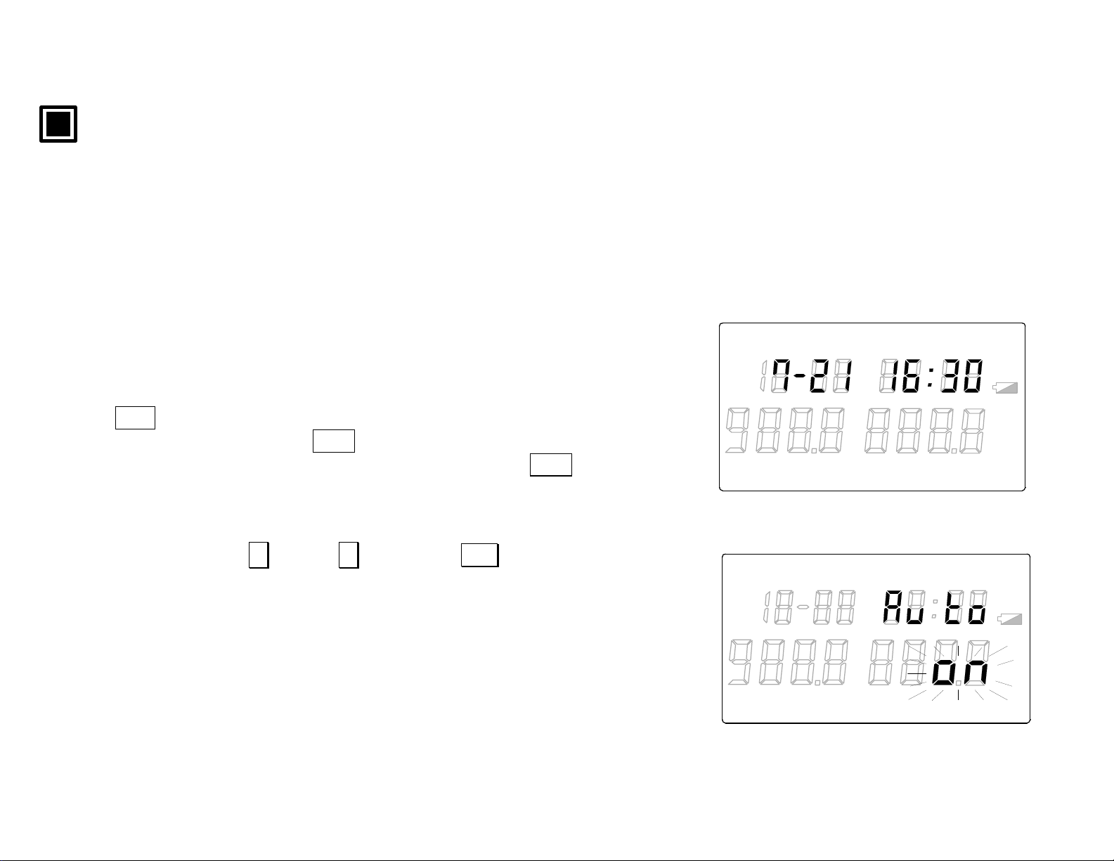
[Auto-power-off function]
For avoiding the comsumption of the ba tteries, the auto-power-off function of
this “temperature/humiditymeter” has been set at ON (active) as a factory
default setting. If no key is pressed for 1 minute, the continuous measurement
will automatically stop and the mode will move to the clock mode.
For setting of the auto-power-off function to OFF:
Press DISP key to go to the continuous measurement mode ( Ref. [1.1Continuous
measureme nt] and then press DISP key again f or about 2 second s to go to
the programm ing mode. In th e programming m ode, press DISP k ey several
times to go to the auto-power-off selection mode with “Auto” lit in the sub
display. In the auto-power-off selection mode, “on” (active) will flash in the
main display 2. For releasing the auto-power-off function, select “oFF”
LOG TIME UNIT ALARM
TERM
READ
Auto-power-off selection mode
Clock mode
°
F
℃
REP
INT REF
LOCK
°FH
℃
%RH
H
(release) by pressing ∧ key or ∨ key. Press ENT key to retain “oFF”
selected. The flashing of “oFF ”will stop.
For the RS-232C communications with Model RH32-C2 (RS-232C
communications type), the use of the AC pow er adapt er (R H3 2-AC110 - sold
separately) is recommended to avoid the consumption of the batteries.
Also, for the RS-485 communications with Model RH32-C4 (RS-485
communications type), make sure to use the AC power adapter
(RH32-AC110 - sold separately) as the batteries will be consumed very rap-
-Preface 2-
LOG TIME UNIT ALARM
TERM
READ
REP
°
F
℃
INT REF
LOCK
°FH
℃
%RH
H
Page 7
INST.No.INE-418-2P1CE
idly .
W arning and safety notices
Ensure the following instructions to use this meter correctly.
!
!
!
!
!
!
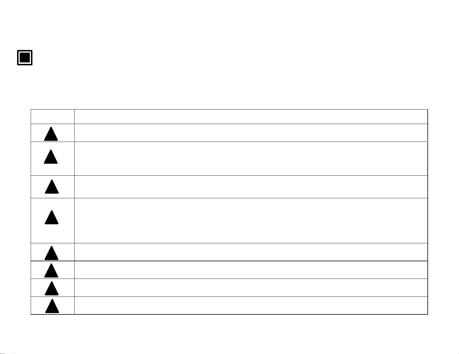
Warning (For avoiding unexpected dangerous accidents of death or serious injury)
◆ Don’t use this meter in places where explosive gas exists.
◆ I f this meter is smoking, nasty smelling or abnorm al noising, remove batteries from it or pull out an AC
power adapter (RH32-AC110) (if used) from a receptacle as quickly as possible, and then contact your
OMEGA ’ s agent.
◆ Don’t throw out batteries in fire. Don’t charge, short circuit, heat or disassemble them.
It will cause a fire or an injury by blowing-out or heat.
◆ For the AC power adapter , use the power voltage of 100 to 240V.
Don’t touch the AC power adapter or the receptacle b y wet hands. It will cause an e lectric shock, a fire or a
failure.
Wipe out dusts from the AC power adapter to prevent fires.
◆ Don’t touch the inside of the case by wet hands.
◆ Don’t repair or modify it.
!
!
◆ Check the specifications of batteries. Use AA (UM-3) batteries.
◆ Don’t use it under failed conditions.
-Preface 3-
Page 8
INST.No.INE-418-2P1CE
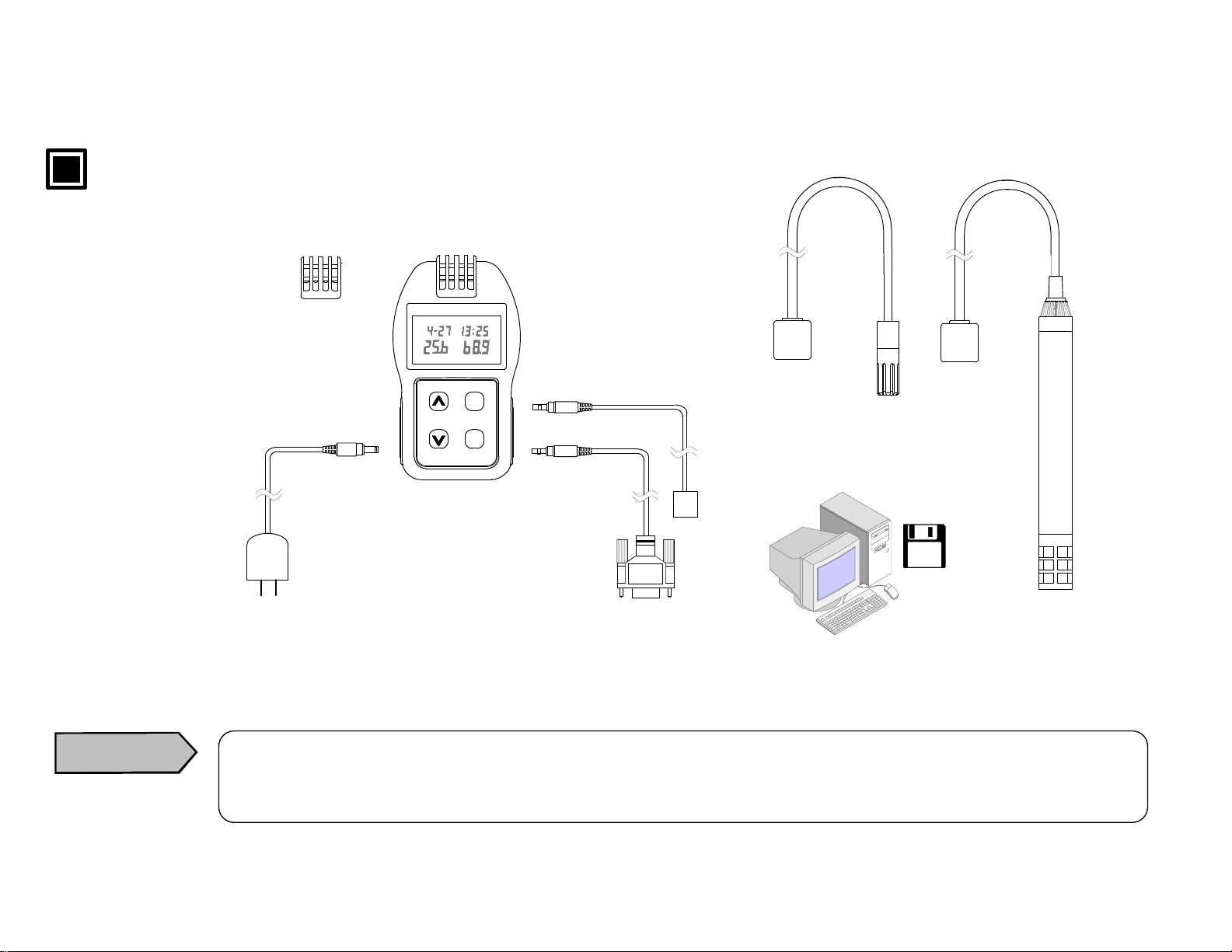
Configuration
Built - in type sensor
RH32B-RP
LOG ALARM
℃
LOCK
Separated type sensor
RH32S-RP
%RH
Caution
AC power adapter
RH32-AC1 10
*
* For the RS-485 communications with Model RH32-C4 (RS-485 communications type), make sure to
use the AC power adapter (RH32-AC1 10- sold separately) as the batteries will be consumed very rapidly.
DISP
SHIFT
LOCK
ENT
LOG
Temperature/humidity meter
RH32B-C2
RH32S-C2
RH32P-C2
RH32B-C4
RH32S-C4
RH32P-C4
*
*
*
RS-232C
communications cable
RH32-S2-CABLE Note)
RS-485
communications cable
RH32-S4-CABLE Note)
Probe type
sensor
RH32P-RP
Data logging
software package
RH32-SW1 Note)
RH32-SW2 Note)
-Preface 4-
Page 9
INST.No.INE-418-2P1CE
Note : Sold separately
conformance
Palm-sized temperature/humidity meter
RH32B-C2,RH32P-C2,RH32S-C2,
RH32B-C4,RH32P-C4,RH32S-C4
Directive
89/336/EEC,92/31/EEC amendment,
93/68/EEC amendment
Standard
EN61326+A1: Emission class B,
Immunity Table1
(Minimum immunity test requirements)
Conformance condition
RH32B-C4:The connection cable is to be used indoor
and within 30m.
RH32P-C4,RH32S-C4:The connection cable is to be
within 3m.
Stability under the test environment of EMC directive
AC power adapter
RH32-AC11 0
EMI standard
Meets the conduction limit of : FCC Class B EN61000-3-2
EN55022 B EN61000-3-3
VCCI II
EMS EN50082-1
IEC801-2 Level3
IEC801-3
IEC801-4
T emperature ±0.5ºC
Relative humidity
±3%RH
-Preface 5-
Page 10

INST.No.INE-418-2P1CE
Contents
Palm-sized temperatur e/hum idity meter <Vol. 2 [Function instructions]>
Request and notices
Importance notices
W arning and safety notices
Configuration
CE conformance
1. Measurement and data storage·····················1
1.1 Conti nuou s m easu remen t ······································1
1.1.1 Measured temperature/
humidit y displa y ra nge································2
1.2 Sto rin g (d ata lo ggi ng) mod e····································3
1.3 Manual stora ge mo de··············································3
1.4 Autom atic stor age mod e··········································4
1.4.1 Automatic storage start/stop
by function keys ······································4
1.4.1-1 Automatic storage start
by function keys········································4
1.4.1-2 Automatic storage stop
by function keys········································4
1.4.2 Automatic storage start/ stop
at storage sta rt/ stop tim e···························5
1.4.2-1 Automatic storage start
at storage sta rt t ime···································5
1.4.2-2 Automatic storage stop
at storage sto p tim e···································5
1.5 Sto rin g int erva l························································6
1.6 Key lock··································································7
2. Flow of stored data reading mode ·············· 8
3. Stor ed data reading mode································ 9
3.1 Number of stored dat a··········································10
3.2 Totalized temperature···········································11
3.3 Maximum temperature/humidity·························13
3.4 Minimum temperature/humidity··························14
3.5 Average temperature/humidity·····························15
3.6 All stored data ······················································16
4. Parameter programming ····························· 17
4.1 Stored data delet ion··············································19
4.2 High alarm set p oi nt·············································20
4.2.1 Temperat ure high ala rm se t po int······················20
4.2.2 Humi dity hig h ala rm se t po int·························21
4.3 Low alarm set point·············································22
4.3.1 Temperature lo w alarm set po int·····················22
4.3.2 Humid ity lo w alarm set po int····························23
4.4 Automatic storage················································24
4.4.1 Storage start time ···········································24
4.4.1-1 Re tai nin g of m ont h·········································24
4.4.1-2 Re tai nin g of d ay·············································25
4.4.1-3 Re tai nin g of h our············································25
4.4.1-4 Re tai nin g of m inu te········································26
4.4.1-5 Re tai nin g of year············································26
4.4.1-6 S t orin g of s tor age star t tim e····························26
4.4.2 St orage stop time ··············································28
4.4.2-1 Re tai nin g of m ont h·········································28
4.4.2-2 Re tai nin g of d ay·············································29
4.4.2-3 Re tai nin g of h our············································29
4.4.2-4 Re tai nin g of m inu te········································30
4.4.2-5 Re tai nin g of year············································30
4.4.2-6 S t orin g of s tor age sto p tim e····························30
4.4.3 St ora ge rep etit ion ·············································32
4.5 Totalizing reference temperature/
totalizi ng di rect ion····························33
4.5.1 Totalizi ng r efe rence tem per atur e·······················33
4.5.2 Totalizing dire ction············································34
4.6 Auto-power-off····················································35
4.7 Instrument No.·····················································36
5. Troubleshooting·············································· 37
-Content-
Page 11
INST.No.INE-418-2P1CE
y
1. Measurement and data storage
Reference
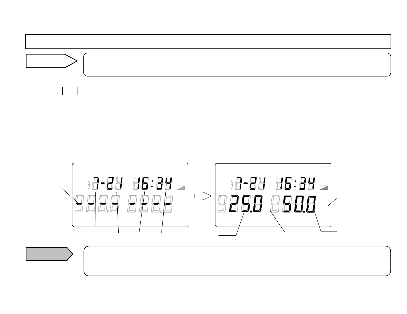
This paragraph describes “Measurement and data logging” of the RH32 series temperature/humidity meter .
For the exact operation, program parameters first in [4 . Parameter programm ing].
1.1 Continuous measurement
By pressing DISP key in the clock mo de, the temperature/humidit y measureme nt will s tart after bars are di splayed for about 1 second . The
measured temperature will be displayed in the main display 1 and the measu red hum id ity wil l be displaye d in the main disp lay 2 together with
the display of month, day , hour and minute at the measurement.
The temperature measurement unit and the humidity measurement unit being displayed are the units already selected.
For the selection of the measurement unit, refer to [5.3 Selection of measurement unit] in the separated instruction manual Vol. 1
<Basic instructions>.
If “ALARM“ lights in the main marker, the measurement value has exceeded a high alarm set point or a low alarm set point. Check the
set points and reprogram them if necessary. Refer to [4.2 High alarm set point] and [4.3 Low alarm set point].
Bar
[Clock display]
LOG TIME UNIT ALA RM
TERM
READ
REP
Month
°
F
℃
INT RE F
Day
Hour
%RH
LOCK
Minute
°FH
H
℃
Main display 1 :
Temperature
[Continuous measurement display]
LOG TIME UNIT ALARM
TERM
READ
°
F
℃
REP
INT REF
Temperature measurement unit
°FH
℃
%RH
LOCK
Main marker
Humidity
measurement unit
H
Main display 2 :
Humidit
Caution
If “Er4“ for “low battery” or “meter abnormal” is displayed in the main display 2, rep lace the b atteries first.
(Ref. [5.1 Load ing of batteries] in the se parated ins truction m anual Vol. 1 <Basic in structions> )
If “Er4“ is still displayed by the above replacement of batteries, contact your OMEGA’s agent.
-1-
Page 12
INST.No.INE-418-2P1CE
1. Measurement and data storage
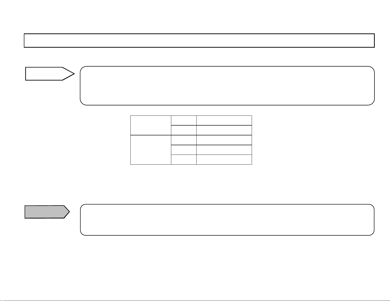
1.1.1 Measured temperature/humidity display range
Remarks
When the clock is di splayed afte r the measu rement for a bout 1 minute , the auto-p ower -off fu nction is “on“ (active).
For continuing the continuous measurement, select the auto-power-off function to “oFF“ (release).
(Ref. [4.6 Auto-power-off ].
Caution
When the measured temperature is lower than the mi nimum limit, “uFL“ will be displayed and, when it is higher
than the maximum limit, “oFL“ will be displayed.
When the measured humidity is 0%, 0% will be displa yed but, when the measured humidi ty is higher t han 100%
(dew condensation), the value will be held at 100%.
Temperature
Humidity
When the auto-power-off function is set to “oFF“ (release) and the continuous measurement is executed, the
batteries will be consumed very rapidly .
For the continuous measurement constantly executed, use the AC power adapter (RH32-AC110) sold separately.
ººC -40 to 80ºC
ºF -40 to 176ºF
%RH 0 to 100%RH
ºC -60 to 80ºC
ºF -76 to 176ºF
-2-
Page 13
INST.No.INE-418-2P1CE
1. Measurement and data storage
1.2 Storing (data logging) mode
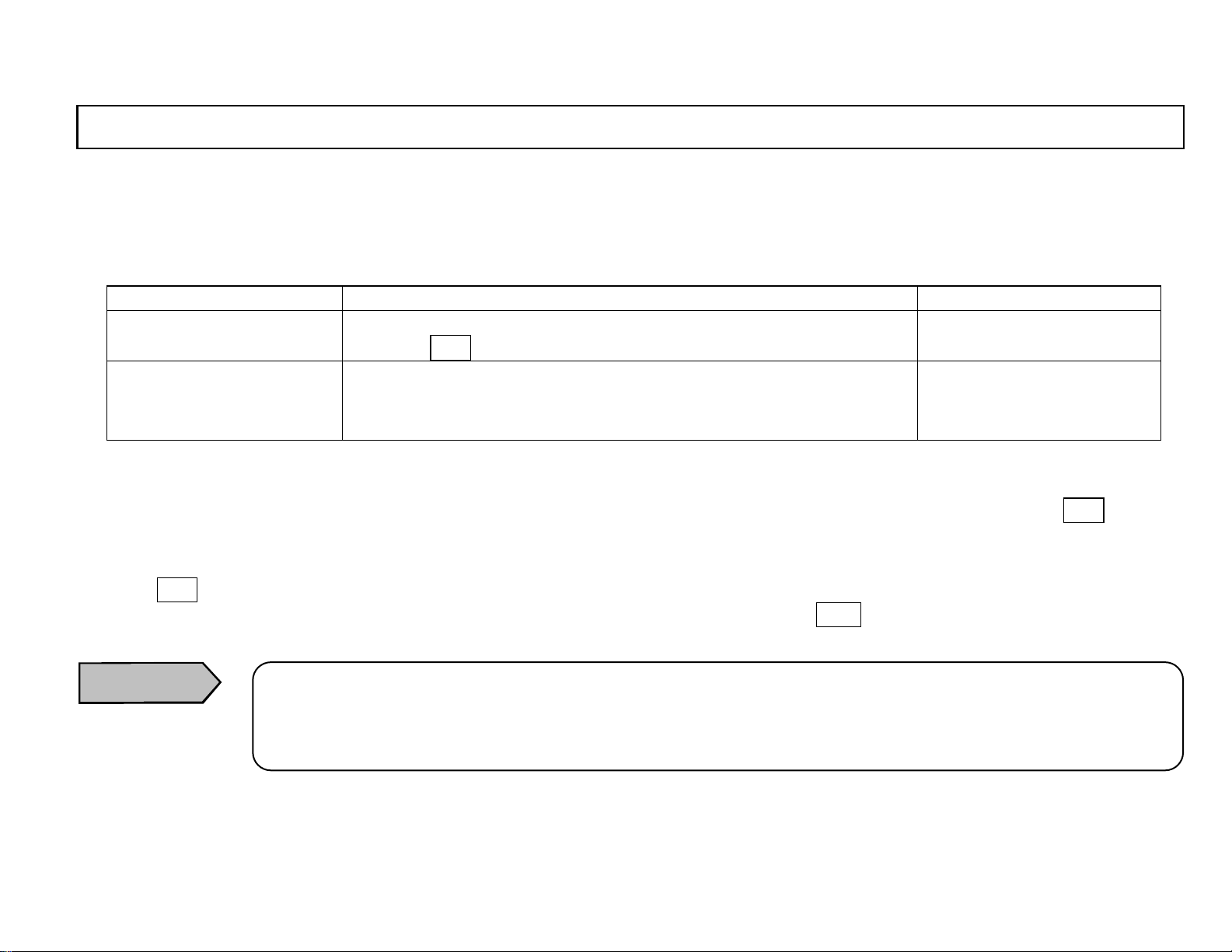
This meter has a memory storing each maximum 8000 da ta of measured temperature and humidity.
The measured data are stored into an EEPROM and can’t be erased even if the batteries are dead.
T wo storing (data logging) modes of manual storage mode and automatic storage mode are available.
Storage mode Content Number of data
Manual storage mode In the continuous measurement, the measured data is stored by
pressing ENT key.
Automatic storage mode The measured data is stored at a storing interval programmed.
The automatic st orage can be started/stopped by the function
keys or at the storage start/stop time programmed.
Temperature/humidity:
Each 1700 data
Temperature/humidity:
Each 8000 data
1.3 Manual storage mode
The temperature measured value and the humidity measured value in the continuous measurement mode are stored by pressing ENT key with
the time data of year , month, day, hour, and minute at th e measurement.
1) Go to the continuous measurement mode. (R ef. [1.1 Contin uous measuremen t])
2) Press ENT key for about 2 seconds. “LOG“ will instantly light in the main marker, and the temperature measured value and the humidity
measured value are stored with the time data of year, month, day, hour , and minute. Release ENT key once.
3) Repeat the procedure 2) for the next data storage.
Caution
The manual storage will be disabled during the automatic storage (with “LOG“ lit in the main marker,
Ref. [1.4 Automa tic s torage] ) or in th e memory full status (number of data: “FuLL“, Ref . [3.1 Sto r e d d a ta nu m ber] , o r in
the key lock a ctive (with “LOC K“ lit in the main marker, Ref. [1.6 Key lock]).
-3-
Page 14
INST.No.INE-418-2P1CE
1. Measurement and data storage
1.4 Automatic storage mode
The measured temperature value and the measured humidity value are stored with the storing interval of minute or hour programmed in
[1.5 Storing interval]. The auto matic storage can be started/st opped by the function keys or at t he storage start/stop time programmed.
During the automatic storage, “LOG“ will ligh t in the m ain marke r .
Caution
The automatic storage will be disabled in the memory full status (number of data: “FuLL“, Ref. [3.1 Stored data
number].
If the me mory become s full (numbe r of data: “FuLL“, Ref. [3.1 Stored data number] or if any hardware becomes
abnormal d uring the a utomat ic storage, the data storage will sto p.
1.4.1 Automatic storage st art/stop by function keys
The automatic storage, with the storing interval programmed in [1.5 Storing interval], of the temperature measured values, the humidity
measured values and the time data of year, month, day, hour, and minute at the measurement starts and stops by the fun ction keys.
1.4.1-1 Automatic storage start by function keys
1) Go to the continuous measurement mode. (Ref. [1.1 Continuous measurement])
2) Confirm “LOG“ is n ot lit (not in storing d ata) in the main marker.
3) Press ENT (LOG) key while pr essing ∧ (SHIFT) key. “LOG“ will light in the marker and the automatic storage will start with the
storing interval programmed. (Ref. [1.5. Storing interval]) “
1.4.1-2 Autom atic storage s top by fun ction keys
In the continuous measurement mode with “LOG“ lit in the main marker, press ENT (LOG) key while pressing ∧ (SHIFT) key.
“LOG“ will go off and the automatic sto rage will stop.
Caution
Caution
The automatic storage can’t start/stop by the function keys in the key lock active (w ith “LOCK“ lit in the main marker,
Ref. [1.6 Key loc k]).
When the storage stop time in the automatic storage has been programmed in [4.4.2 Storage stop t ime] and the automatic storage starts by the function keys, the automatic storage will st op at the s tor ag e st op t i me bein g programmed.
-4-
Page 15
INST.No.INE-418-2P1CE
y
)
1. Measurement and data storage
1.4.2 Au tomatic s torage st art/s top at storage st ar t/stop time
The automatic storage, with the storing interval programmed in [1.5 Storing interval], of the temperature measured values, the humidity
measured values and the time data of year, month, day, hour, and minute at the meas urement s tarts at the storage st art ti me (year, month, day,
hour, and minute) programmed in [4.4.1 Storage start time] and stops at the storage stop time (year, month, day , hour, and minute) programmed
in [4.4.2 Storage stop time]. The storage repetition per day or week is available, too.
For the details of programming, refer to [4.4.1 Storage start time], [4.4.2 Storage stop time], and [4.4.3 Storage repetition].
1.4.2-1 Au tomatic storage st art at storage st art time
The automatic storage will automatically start at the storage start time programmed in [4.4.1 Storage start time].
1.4.2-2 Au tomatic storage stop at storag e stop time
The automatic storage will automatically stop at the storage stop time programmed in [4.4.2 S torage stop tim e].
Caution
After the automatic stor age starts at the storage start time programmed, the automatic storage can be stopped by the
function ke
s. (Refer to [1.4.1-2 Automatic storage stop by function keys].
-5-
Page 16
INST.No.INE-418-2P1CE
1. Measurement and data storage
1.5 Storing interval
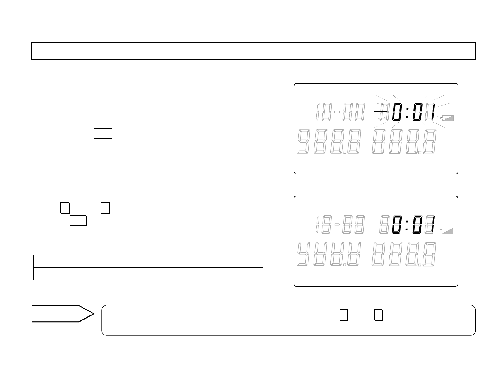
This is the programming mode for the storing interval for the automatic
storage.
In the [4.4.3 Storage repetiti on] program ming mode wit h “REP“ lit in the
LOG TIME UNIT ALARM
READ
main marker, press DISP ke y to go to the storing interval progra mming
mode. In the stori ng interval programming mode, “INT“ will light in the
main marker and “0:01“ will flash in the sub display.
Select the desired storing interval from 0.01 (1 minute) to 1.00 (1 hour) by
pressing ∧ key or ∨ key.
By pressing ENT key, the storing interval selected will be retained and the
flashing of the storing interval will stop.
0:01 (1 minute) to 1:00 (1 hour) 0:01
Programming range Default
°
F
℃
TERM
LOG TIME UNIT ALARM
REP
READ
INT REF
°
F
LOCK
℃
TERM
REP
INT REF
LOCK
°FH
℃
%RH
°FH
℃
%RH
H
H
Remarks
In the programmi ng of the storing interval, t he continuously pressing of ∧ key or ∨ key will make the value
change rapidly.
-6-
Page 17
INST.No.INE-418-2P1CE
1. Measurement and data storage
1.6 Key lock
When you do not want to change parameters programmed, use the key lock not to function any keys.
The key lock will be required in some cases fo r the communications with the data logging software package (RH32-SW□: sold separately).
(For details, refer to the separate instruction manual for [Data logging software package].)
Caution
When the key lock is active, the programming by the function keys will be disabled.
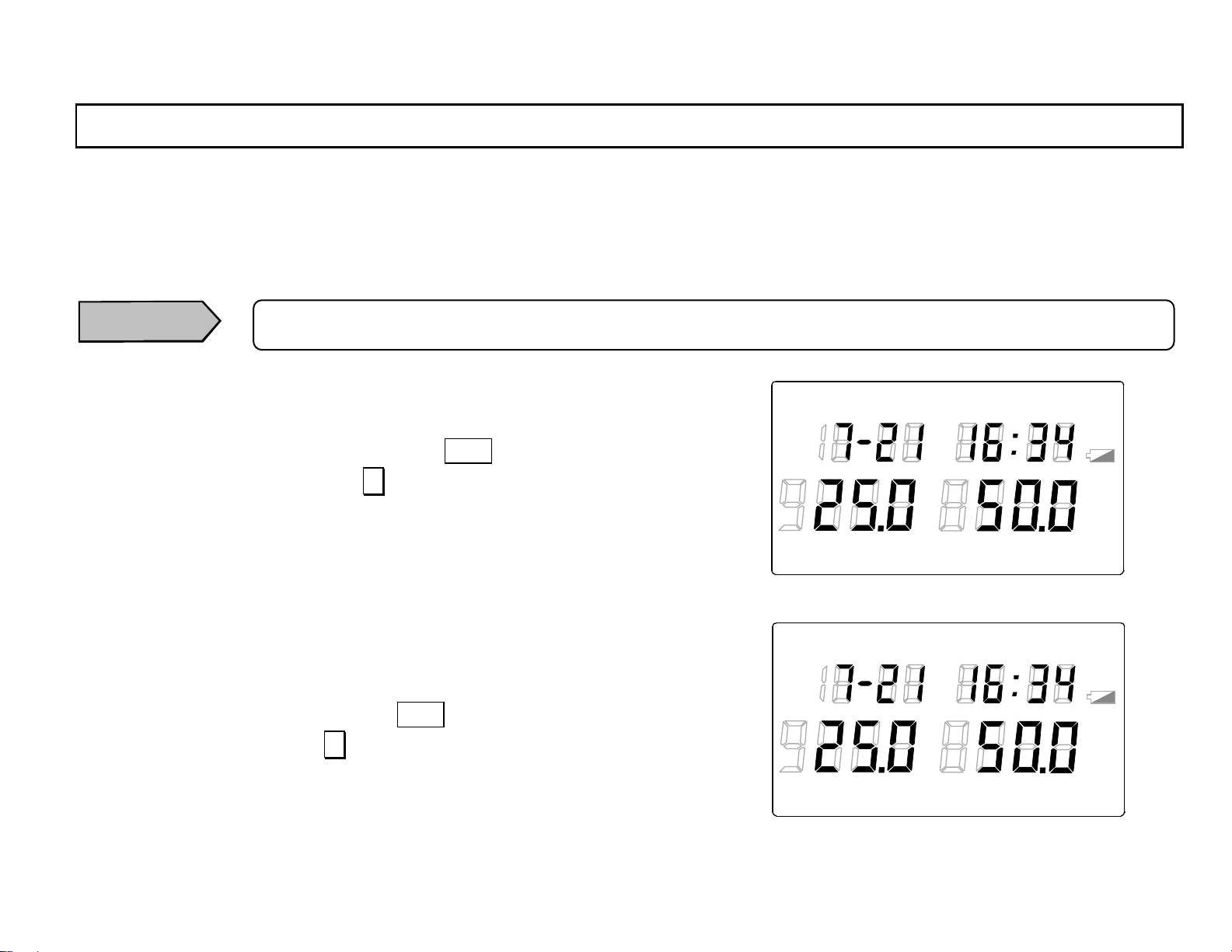
1) Key lock setting: In the continuous measurement mode with
“LOCK“ not lit (key lock - released) in the
main marker, press DISP (LOCK) key while
pressing ∧ (SHIFT) key. “LOCK“ will light
in the main marker and the key lock will
become active.
2) Key lock release: In the continuous measurement mode with
“LOCK“ lit (key lock - active) in the main
marker, press DISP (LOCK) key while pressing ∧ (SHIFT) key. “LOC K“ will go off in
the main marker and the key lock will be
released.
LOG TIME UNIT ALARM
TERM
READ
REP
°
F
℃
INT RE F
%RH
LOCK
[Key lock – active]
LOG TIME UNIT ALARM
TERM
READ
REP
°
F
℃
INT RE F
%RH
LOCK
°FH
℃
°FH
℃
H
H
[Key lock – released]
-7-
Page 18
INST.No.INE-418-2P1CE
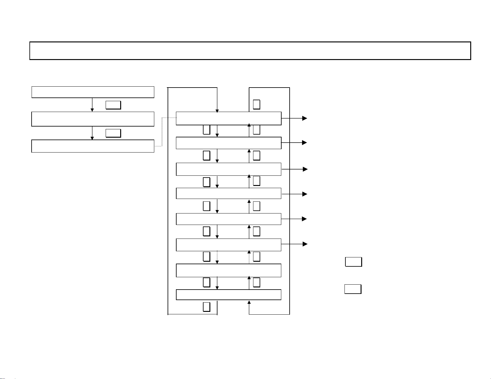
2. Flow of stored dat a reading mode
The followings are the flow of the stored data reading mode.
Continuous measurement mode
S tored data reading mode
Clock mode
DISP
S tored data number scree n
DISP 2 sec.
Totalized temperature screen
∧
[3.1 Number of stored dat a]
∧∨
[3.2 T otalized temperature]
∧∨
Max. temp/hu m screen
∨
∧
Min temp/hum screen
∧∨
Ave temp /hum scre en
∧∨
[3.3 Maximum temperatur e/humidity]
[3.4 Minimum temper ature/humi dity]
[3.5 Average temperature/humidity]
S tored data screen (1 )
[3.6 All stored dat a]
∧∨
S tored dat a screen (n1)
∧∨
Stored data screen (n)
∨
-8-
・ By pressi ng DISP key for 2 seconds in any screen
in the stored data reading mode, the mode will move
to the continuous measurement mode.
・By pres sing DISP key for a sho rter period than 2
seconds in any screen in the stored data reading
mode, the mode will move to the [4.1Stored data
deletion] mode .
・When the auto-power-off function is ON (active), if no
key is pressed for 1 m inute, the mode will automatically move to the clock mode.
Page 19
INST.No.INE-418-2P1CE
削除
3. Stored data reading mode
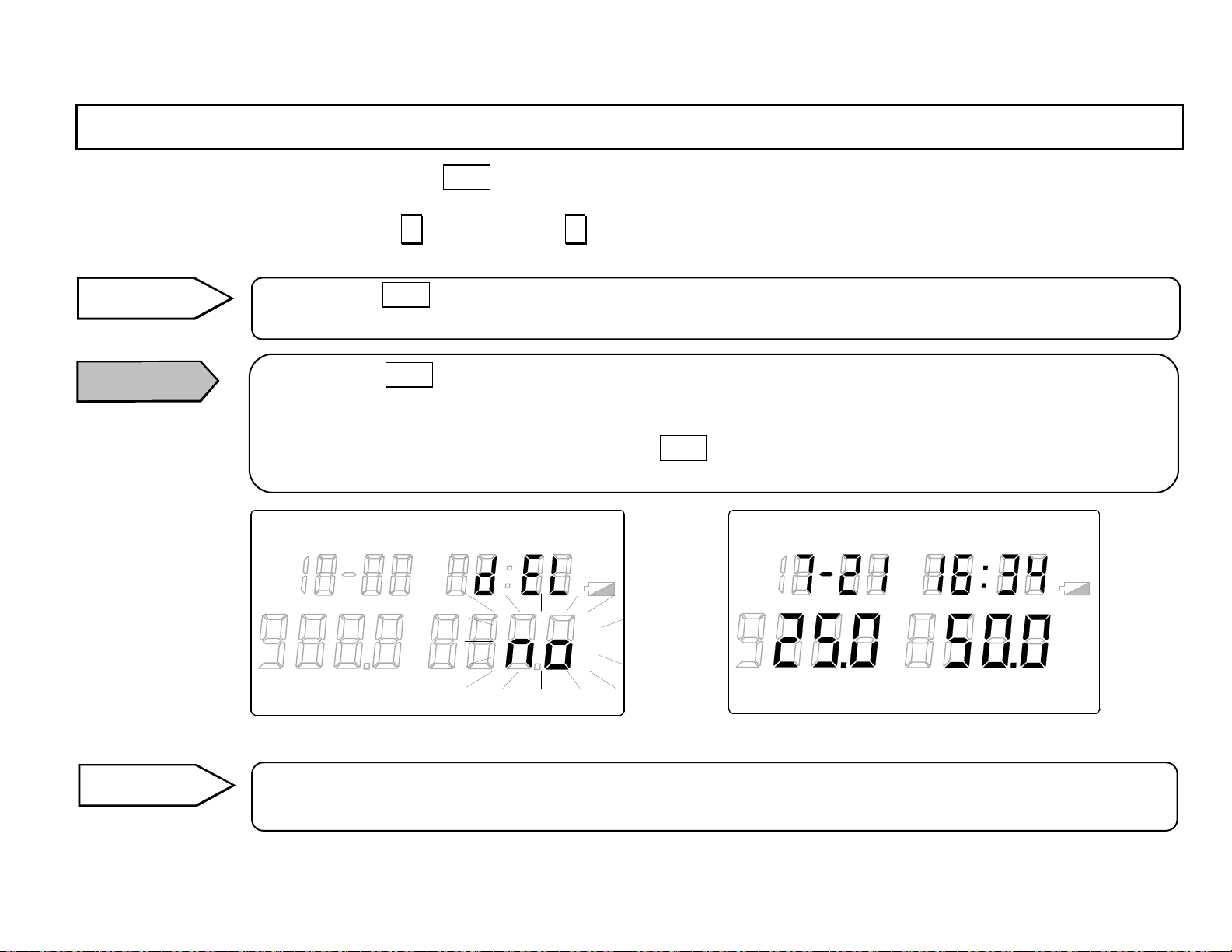
In the continuous measurement mode, press DISP key for 2 second to go to the stored data reading mode with “READ“ lit in the main
marker.
In the stored data reading mode, press ∧ (SHIFT) key or ∨ key to show 6 screens from the [3.1 Number of stored data] screen to the
[3.6 All sto red data] screen.
Remarks
Caution
By pressing DISP key for 2 seconds in any screen in the stored data reading mode, the mode will move to the
continuous measurement mode.
By pressing DISP key for a shorter period than 2 sec onds in any screen in the stored data reading mode, the
mode will move to the [4.1 Stored data deletion] mode (“dEL“ lights in the sub display and “no“ flashes in the
main display 2.).
If the data deletion mode is not required, press DISP key for 2 seconds in t his mode to go to the continuous
measurement mode.
Reference
LOG TIME UNIT ALARM
TERM
READ
REP
°
F
℃
INT RE F
%RH
LOCK
[Stored data deletion mode]
°FH
℃
H
LOG TIME UNIT ALARM
TERM
READ
REP
°
F
℃
INT RE F
%RH
LOCK
[Continuous measurement mode]
°FH
℃
H
For avoiding the comsumption of the batteries, the auto-power-off function of this meter has been set at ON (active)
as a factory default setting. If no key is pressed for 1 minute, the mode will automatically move to the clock mode.
-9-
Page 20
INST.No.INE-418-2P1CE
3. Stored data reading mode
3.1 Number of stored dat a
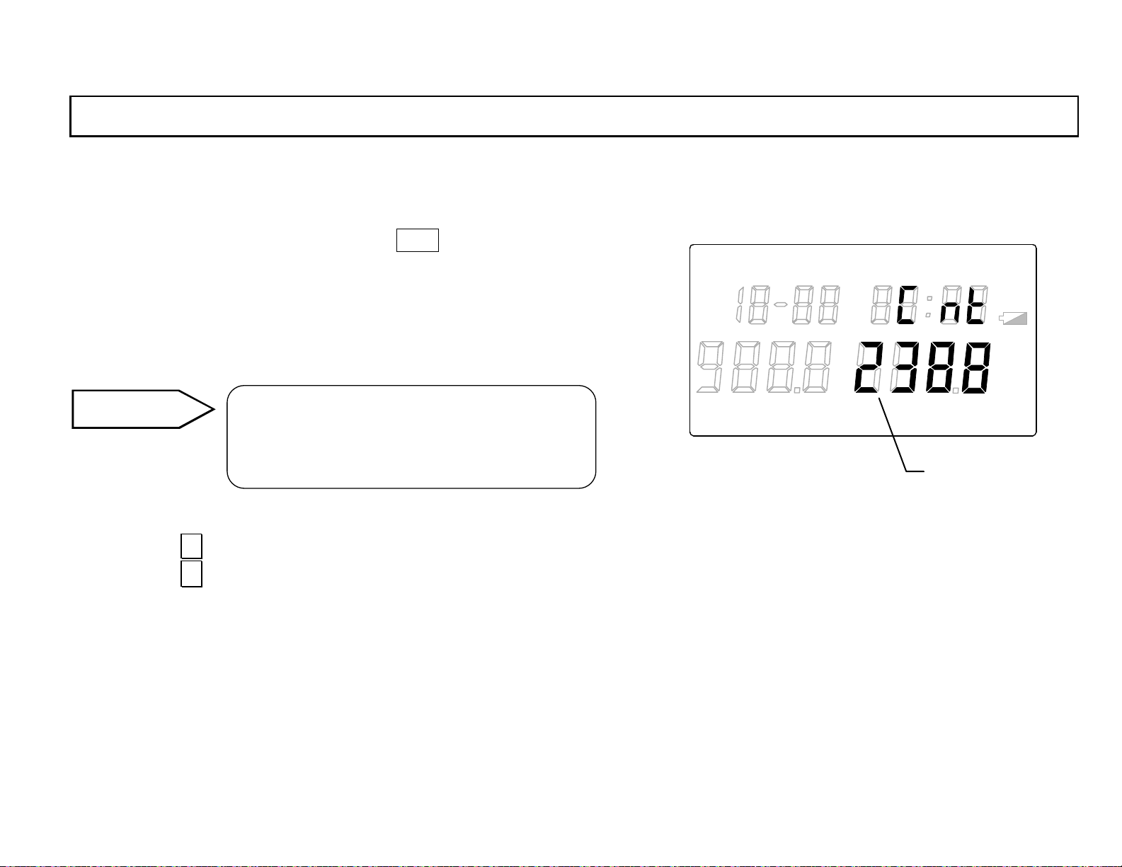
This screen displays the number of stored data.
In the continuous measurement mode, press DISP key for 2 sends to go
to the number of stored data screen (“READ“ will light in the main
marker and “Cnt“ will light in the sub display.). In the number of stored
data screen, the number of the stored data will be displayed in the main
display 2.
Reference
If the memory is full (when the number of the
stored data exceeds the maximum limit),
“FuLL“ will be displayed in th e main display 2.
LOG TIME UNIT ALARM
TERM
READ
REP
°
F
℃
INT REF
°FH
H
℃
%RH
LOCK
Main display 2
By pressing ∨ key, the screen will move to the [3.2 T otalized temperature] screen.
By pressing ∧ key, the screen will move to the [3. 6 All stored data] scre e n .
-10-
Page 21
INST.No.INE-418-2P1CE
3. Stored data reading mode
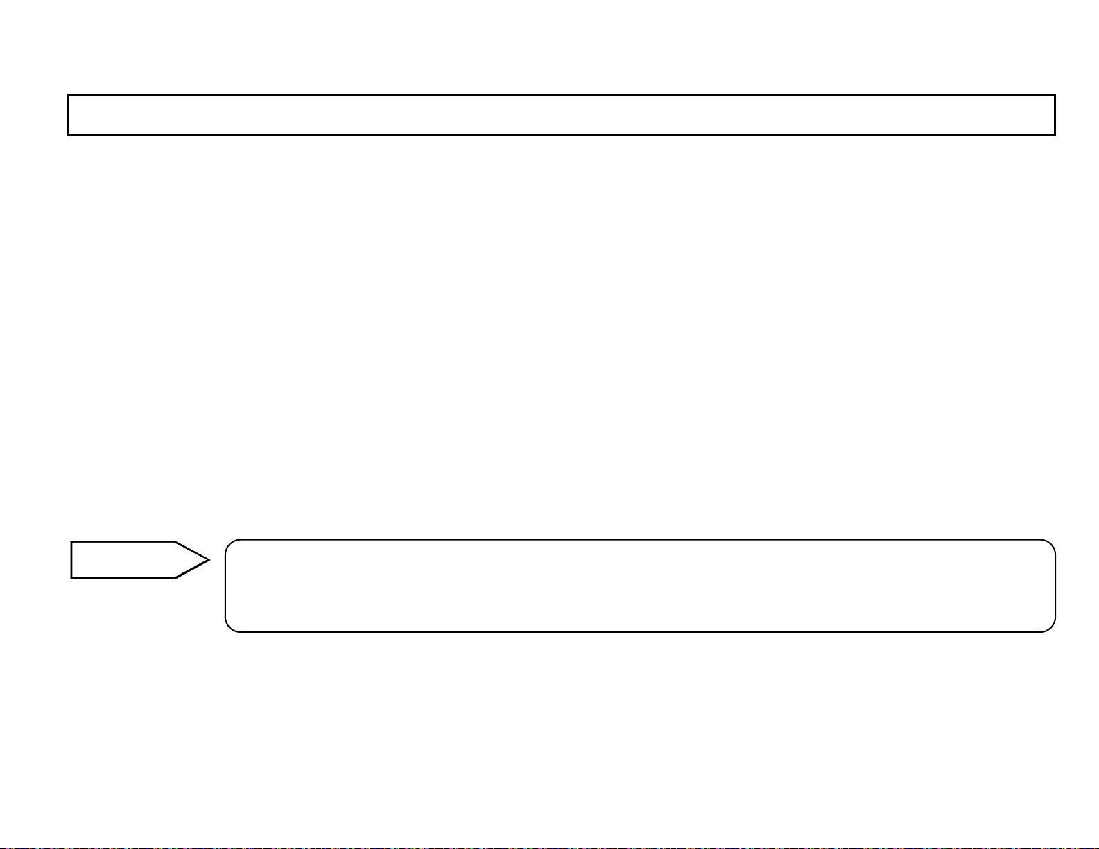
3.2 Totali zed temp erature
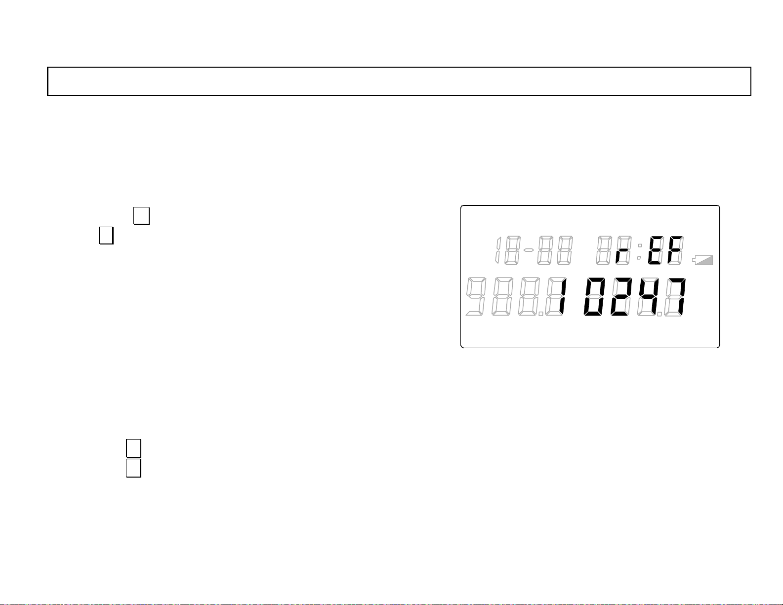
This screen d isp lays the tota lize d temp eratu re b y a to tal izin g reference temperature programmed in [4.5 .1 Totalizing reference temperature] and
a totalizing d irection p rogrammed in [4.5 .2 Totalizing direction] .
In the [3.1 Number of stored d ata] screen with “READ“ lit in the main
marker, press ∨ key to go to the totalized temperature screen
LOG TIME UNIT ALARM
READ
(“rEF“ ∨ key will will light in the sub display.). In the totalized
temperature screen, the totalized temperature (0 to 19999999) of the
data stored by the storage mode just before the pressing of be displayed
in the main display 2. (If the storage mode just before is the manual
storage, the totalized temperature of 1 data stored manually will be
displayed.)
TERM
REP
“ºCH“or “ºFH“ will light depend ing o n th e measu rem ent un it at the da ta
storage.
(Ref. [5.3 Measurement unit selection] in the separate instruction manual
Vol. 1 <Basic instruction s>)
By pressing ∨ key, the screen will move to the [3.3 Maximum temperature/humidity] screen.
°
F
℃
INT RE F
%RH
LOCK
°FH
℃
H
By pressing ∧ key, the screen will move to the [3.1 Number of stored data] screen.
-11-
Page 22
INST.No.INE-418-2P1CE
3. Stored data reading mode
<< Definition of totalized temperature>>
The totalized temperature is computed by the following formula.
1) H totalized temperature = (Measured temperature – totalizing reference temperature) x Hour
Note: Computed only at
Measured temperature – totalizing reference temperature > 0
2) L totalized temperature = (Totalizing reference temperature - measured temperature) x Hour
Note: Computed only at
T otalizing reference temperature - measured temperature > 0
Ex. 1) If the totalizing referen ce temperature is 0.0 ºC and the measured temperature was 25.0ºC for 100 hours, the H totalized temperature is:
(25.0 - 0)x100 = 2500ºCH
Ex. 2) If the totalizing reference temperature is 10.0ºC, and the measured temperature was 25.0ºC for 100 hours, 15.0ºC for 50 hours and 5.0ºC
for 100 hours, th e H total ized temperature is :
(25.0 - 10.0) x 100 +(15.0 - 10.0) x 50 = 1555ºCH
Ex. 3) If the totalizing reference temperature is 10.0ºC, and th e measured temperature was 25.0ºC for 100 hours, 15.0ºC for 50 hours and 5.0ºC
for 100 hours, the L totalized temperature is:
(10.0 - 5.0) x 50 = 250ºCH
Remarks
The totalizing direction (H or L) and the totalizing reference temperature are programmed in [4.5Totalizing
reference temperature/totalizing directio n].
For the details, refer to [4.5Totalizing reference temperature/totalizing direction].
-12-
Page 23
INST.No.INE-418-2P1CE
3. Stored data reading mode
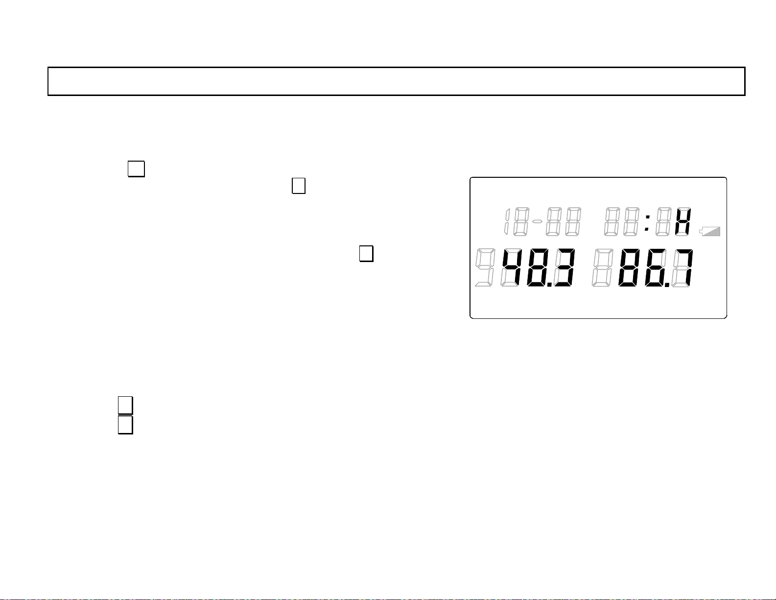
3.3 Maximum temperature/humidity
This screen display s the maximum te mperature and the maximu m humidity in the data stor ed in [1 .2 Sto ring (data lo gging) m ode].
By pressing ∨ key in the [3.2 Totalized temperature] screen with
“READ“ lit in the main marker, or by pressing ∧ key in th e [3 .4 Mi n im u m
LOG TIME UNIT ALARM
READ
temperature/humidity] screen, the screen will move to the maximum
temperature/humidity screen (“H“will light in the sub display.). In the
maximum temperature/humidity screen, the maximum temperature in the
data stored by the storage mode just before the pressing of ∨ key will be
displayed in the main display 1 and the maximum humidity will be displayed
in the main display 2. (If the storage mode just before is the manual storage,
the data stored manually will be displayed.)
TERM
REP
The temperature unit of ºC or ºF and the humidity unit of %RH, ºC or ºF will
light depending on the m easuremen t unit at th e data sto rage.
(Ref. [5.3 Measurement unit selection] in the separate instruction manual Vol. 1
<Basic instructions>)
By pressing∨ key, the screen will move to the [3.4 Minimum temperature/humidity] screen.
By pressing∧ key, the screen will move to the [3.2 Totalized temperature] screen.
°
F
℃
INT RE F
%RH
LOCK
°FH
℃
H
-13-
Page 24
INST.No.INE-418-2P1CE
3. Stored data reading mode
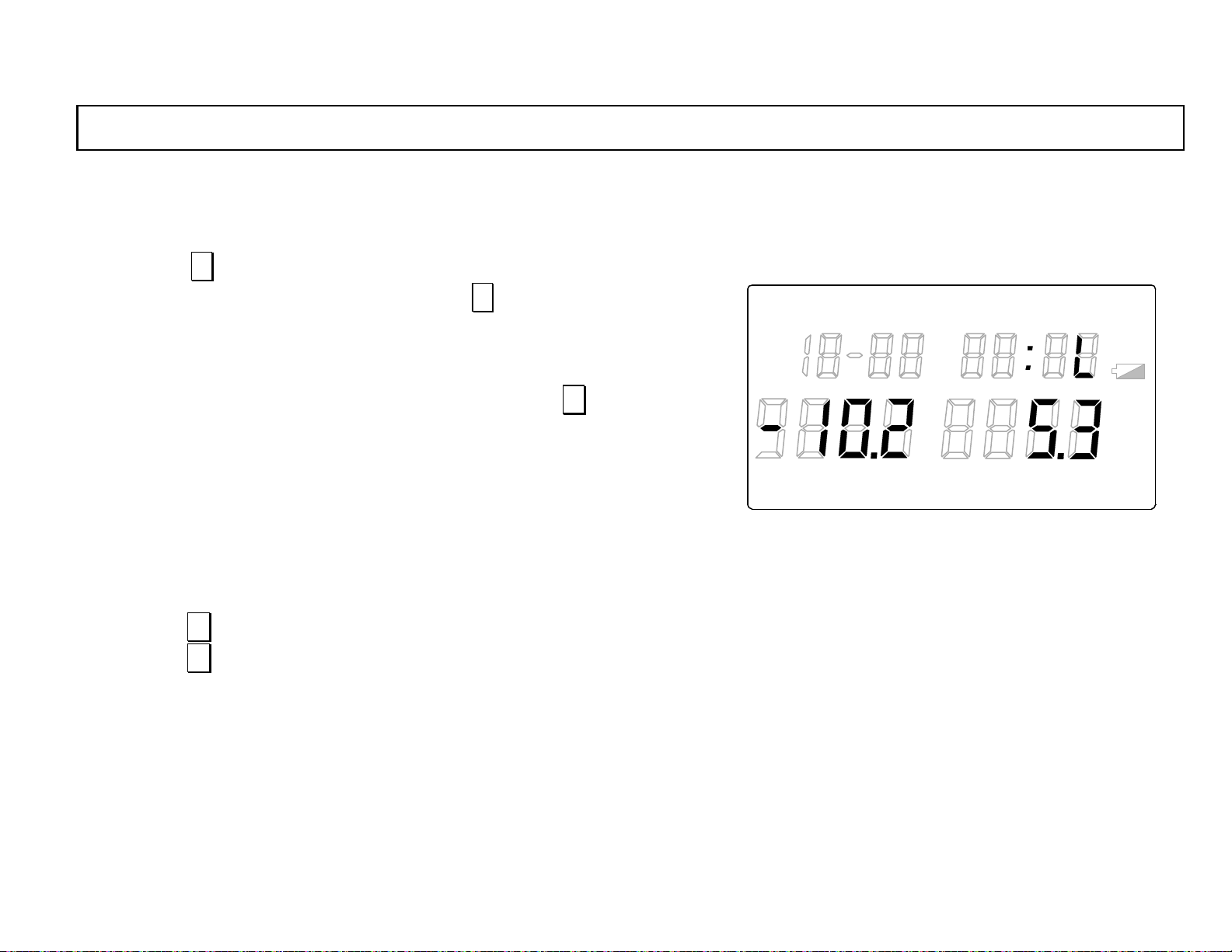
3.4 Minimum temperature/humidity
This screen display s the minimum te mperature and the minimu m humidity in the da ta stored in [1.2 Storing (data logging) mode].
By pressing ∨ k e y i n the [3.3 Maxi mum temp eratur e/humidi ty] scr een with
“READ“ lit in the main marker or by pressing ∧ key in the [3.5 Average
LOG TIME UN IT ALARM
READ
temperature/humidity] screen, the screen will move to the minimum
temperature/humidity screen (“L“ will light in the sub display.). In the
minimum temperat ure/humidity screen, the minimum temperature in the data
stored by the storage mode just before the pressing of ∨ key will be
displayed in the main display 1 and the minimum humidity will be displayed
in the main display 2. (If the storage mode just before is the manual storage,
the data stored manually will be displayed.)
The temperature unit of ºC or ºF and the humidity unit of %RH, ºC or ºF will
TERM
light depending on the m easuremen t unit at th e data sto rage.
(Ref. [5.3 Measurement unit selection] in the separate instruction manual Vol. 1
<Basic instructions>)
By pressing∨ key, the screen will move to the [3.5 Average temperature/humidity] screen.
By pressing∧ key, the screen will move to the [3.3 Maximum temperature/humidity] screen.
REP
°
F
℃
INT REF
%RH
LOCK
°FH
H
℃
-14-
Page 25
INST.No.INE-418-2P1CE
3. Stored data reading mode
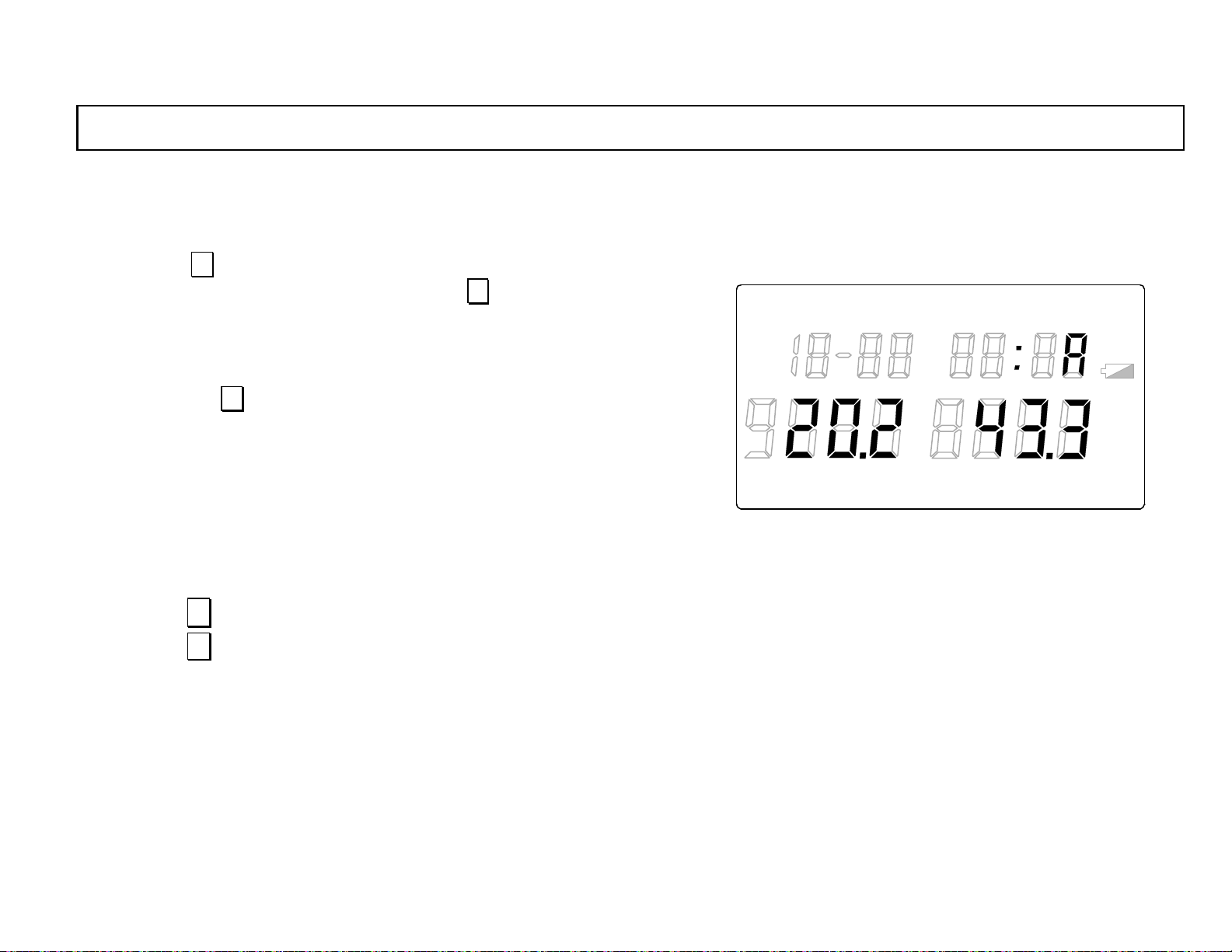
3.5 Averag e temperature/humidity
This screen displays the average temperature and the av erage humidity in the d ata stored in [1.2 S toring (data logging) mode].
By pressing ∨ key in the [3.4 Mi nimum temperature/humidity] screen with
“READ“ lit in the main marker or by pressing ∧ key in the display of the
LOG TIME UNIT ALARM
READ
oldest stored data in the [3.6 All stored data] screen, the screen will move to
the average temperature/humidity screen (“A “will light in the sub display.).
The average temperature in the data stored by the storage mode just before
the pressing of ∨ key will be displayed in the main display 1 and the
average humidity will be displayed in the main display 2. (If the storage mode
just before is the manu al storage, the data stored manually will be displayed.)
The temperature unit of ºC or ºF and the humidity unit of %RH, ºC or ºF will
TERM
REP
light depending on the m easuremen t unit at th e data sto rage.
(Ref. [5.3 Measurement unit selection] in the separate instruction manual Vol. 1
<Basic instructions>)
By pressing∨ key, the screen will move to the [3.6 All stored data] screen.
By pressing∧ key, the screen will move to the [3.4 Minimum temperature/humidity] screen.
°
F
℃
INT REF
%RH
LOCK
°FH
℃
H
-15-
Page 26
INST.No.INE-418-2P1CE
3. Stored data reading mode
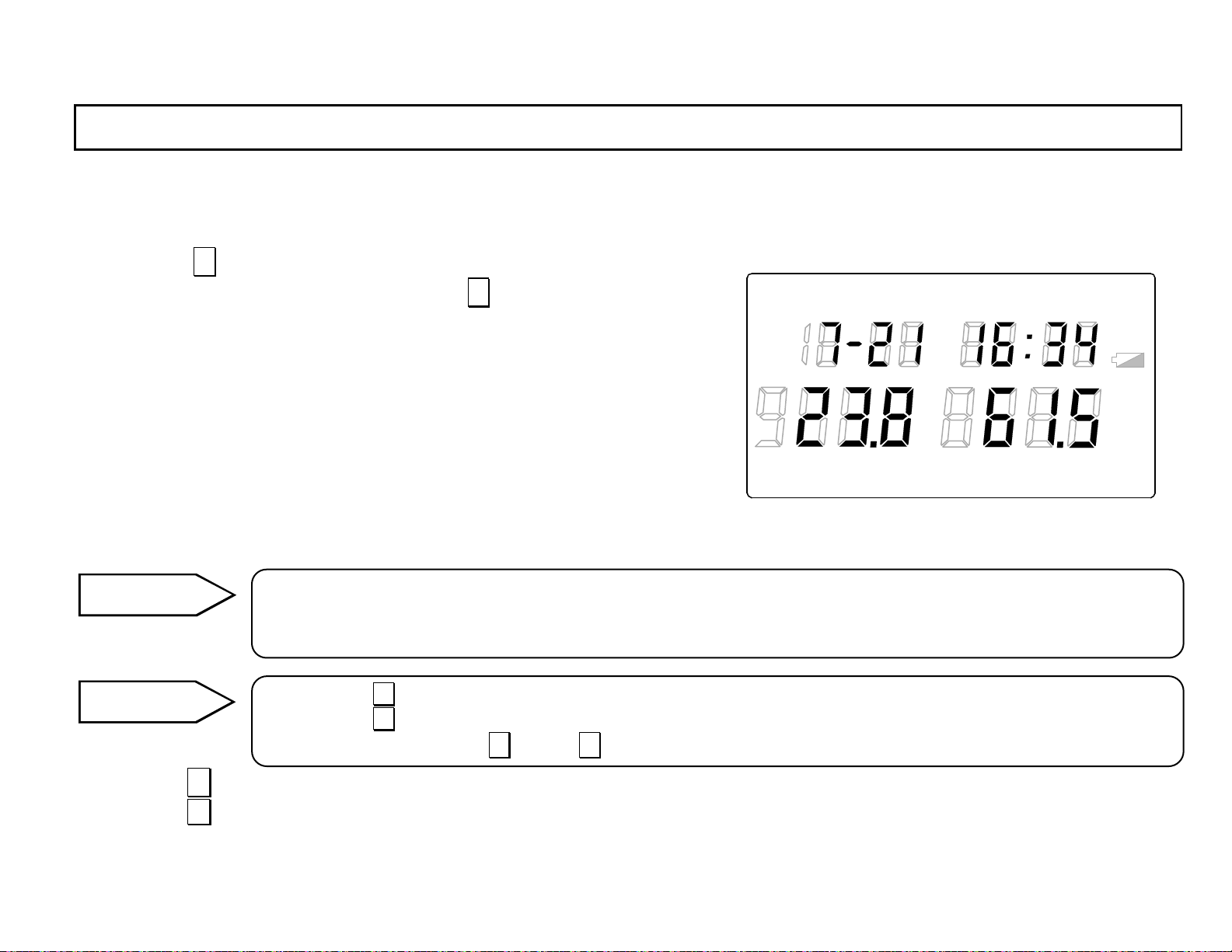
3.6 All stored data
This screen displays all stored temperature and humidity stored in [1.2 Storing (data logging) mode].
By pressing ∨ key in the [3.5 Average temperature/humidity] screen with
“READ“ lit in the main marker or by pressing ∧ key at the di splay of the
oldest stored data in the [3.1 Stored data number] screen, the scr een w il l m o v e
to the all stored data screen (“m onth”, “day”, “hour” and “minute” light
in the sub display.). In the all stored data screen, the stored temperature will
be displayed in the main display 1 and the stored humidity will be di splayed
in the main display 2 .
The temperature unit of ºC or ºF and the humidity unit of %RH, ºC or ºF will
light depending on the m easuremen t unit at th e data sto rage.
In addition, “ALARM“ will light in the main marker if the alarm is activated.
(Ref. [5.3 Measurement unit selection] in the separate instruction manual Vol. 1
<Basic instructions> and [4.2 High alarm set point]/[4.3 Low alarm set point] in
this ma nua l)
Reference
When the screen moves from the [3.5 Average temperature] screen, the oldest stored data will be displayed.
When the screen moves from the [3.1 Number of stored data] screen, th e newest stored data will be displayed.
If no stored data exists, 0 will be displayed in the data of month, day , temperature and humidity.
Remarks
By pressing ∧ key , the data will change to the older stored data one by on e.
By pressing ∨ key , the data will change to the newer stored data one by one.
The continuous pressing of ∧ key or ∨ key will make the displayed data change rapidly.
LOG TIME UNIT ALARM
TERM
READ
REP
°
F
℃
INT REF
%RH
LOCK
°FH
H
℃
By pressing∨ key, the screen will move to the [3.1 Number of stored data] screen.
By pressing∧ key, the screen will move to the [3.5 Average temperature/humidity] screen.
-16-
Page 27
INST.No.INE-418-2P1CE
i
n
4. Parameter programming
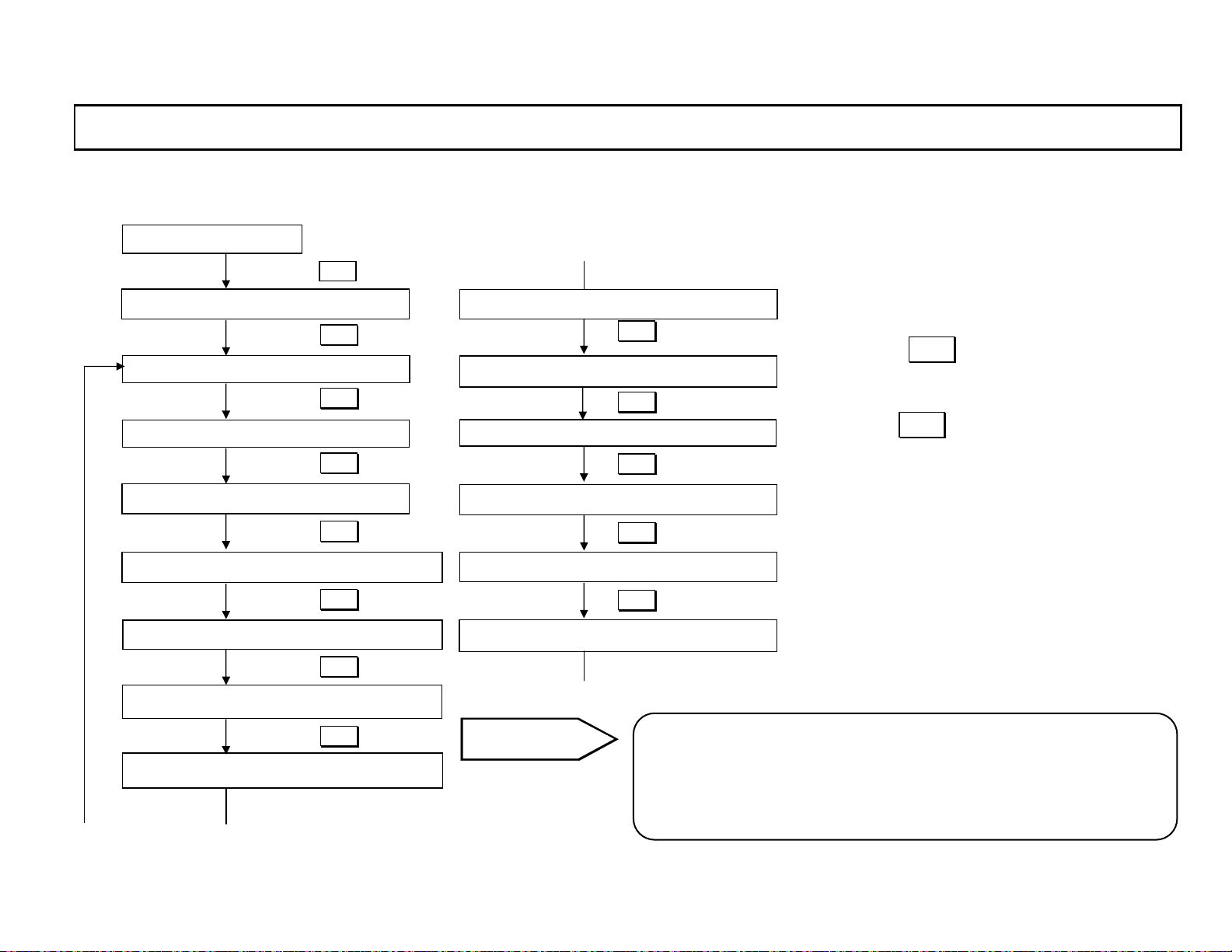
The followings are the flow of the parameter programming.
B
○
Clock mode
DISP
Continuous measuremen t mode
DISP 2 sec
S tored data reading mode
DISP
Stor ed dat a deletion mode
DISP
Clock adjustment mode
DISP
Measurement unit selection mode
DISP
High alarm setpoint programming mode
DISP
Low alarm setpoint pr ogramming mode
DISP
Storage start time programming mode
A
○
*
*2
1
A
○
Storage stop time programming mode
DISP
Storage repetition programming mode
DISP
Storing interval programming mode
DISP
Totalizing function programming mode
DISP
Auto-power-off selection mode
DISP
Instrument No. programming mode
B
○
Reference
*1: Refer to [5.2 Clock adjustment] in the separate instruction
manual Vol.1 <Basic instructions>.
*2: Refer to [5.3 Measurement unit selection] in the separate
instruction manual Vol.1 <Basic
-17-
・By pressing DISP key for 2 seconds in any
mode, the mode will move to the continuous
measurement mode .
・By pressing DISP key for a shorter period than
2 seconds in any screen of the stored data
reading mode, the mode will move to the
stored data deletion mode.
・ When the auto-power-off function is ON
(active), if no key is pressed for 1 minute, the
mode will automatically move to the clock
mode.
structions>.
Page 28
INST.No.INE-418-2P1CE
4. Parameter programming
In the parameter programming modes, the current parameter is displayed and its display flashes when the programming is enabled.
The parameter programmed by pressing ∧ key or ∨ key is retained by pressing ENT key .
Remarks
Caution
Caution
In the parameter programming modes, by pressing DISP key for 2 seconds, the mode will move to the continuous
measurement mode.
By pressing DISP key for a shorter period than 2 sec onds in any screen in the stored data reading mode, the
mode will move to the [4.1 Stored data deletion] mode (“dEL“ lights in the sub display and “no“ flashes in the
main display 2.).
If the data deletion mode is not required, press DISP key for 2 seconds in t his mode to go to the continuous
measurement mode.
The parameter programming will be disabled during the automatic storage (with “L O G “ lit in the main marker, Ref. [1.4.
Automatic storage]) or in the memory full status (number of data: “FuLL“, Ref. [3.1 Stored data number ], or in the key
lock active (“LO C K “ lights in the main marker. Ref. [1.6 Key lock]).
During the data bei ng programmed is fl ashed, if DISP key is pressed for 2 seconds, the data being programmed
becomes invalid.
Reference
For avoiding the coms umpt ion of t he bat teri es, the auto-p ower-off function of this met er has been set at ON (active)
as a factory default setting. If no key is pressed for 1 minute, the mode will automatically move to the clock mode.
-18-
Page 29
INST.No.INE-418-2P1CE
4. Parameter programming
4.1 Stored data deletion
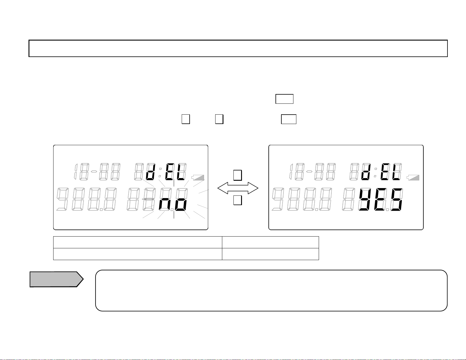
This is the mode for deleting the data stored in [1.2 S toring (data logging) m ode].
In [3. Stored data reading mo de ] wit h “READ“ lit in the main marker, by pressing DISP key, the mode will move to the store d data dele ti on
mode (“dEL“ will light in the sub display and “no “ will flash in the main display 2.). In the stored data deletion mode, select “no“ (deletion
disable) or “YES“ (deletion enabled) by pressing ∧ key or ∨ key and then press ENT key to retain it. The flashing of the function selected
will stop.
LOG TIME UNIT ALARM
TERM
Programming function Default
no (deletion disabled),YES(deletion enabled)
Caution
READ
REP
LOG TIME UNIT ALARM
READ
∧
%RH
LOCK
°FH
℃
H
°
F
℃
INT REF
%RH
LOCK
°FH
H
℃
∨
TERM
REP
°
F
℃
INT REF
no (deletion disabled)
When “YES“ ( deletion enabled) is selected, all stored data will be deleted.
When the data storage for a l ong term is require d, the data st orage int o a personal computer usi ng the data loggi ng
software package (sold separately) is recommended.
-19-
Page 30
INST.No.INE-418-2P1CE
4. Parameter programming
4.2 High alarm set poin t
This is the programm ing mode fo r the high alarm set point applied to the data stored in [1.2 S toring (data logging) mode].
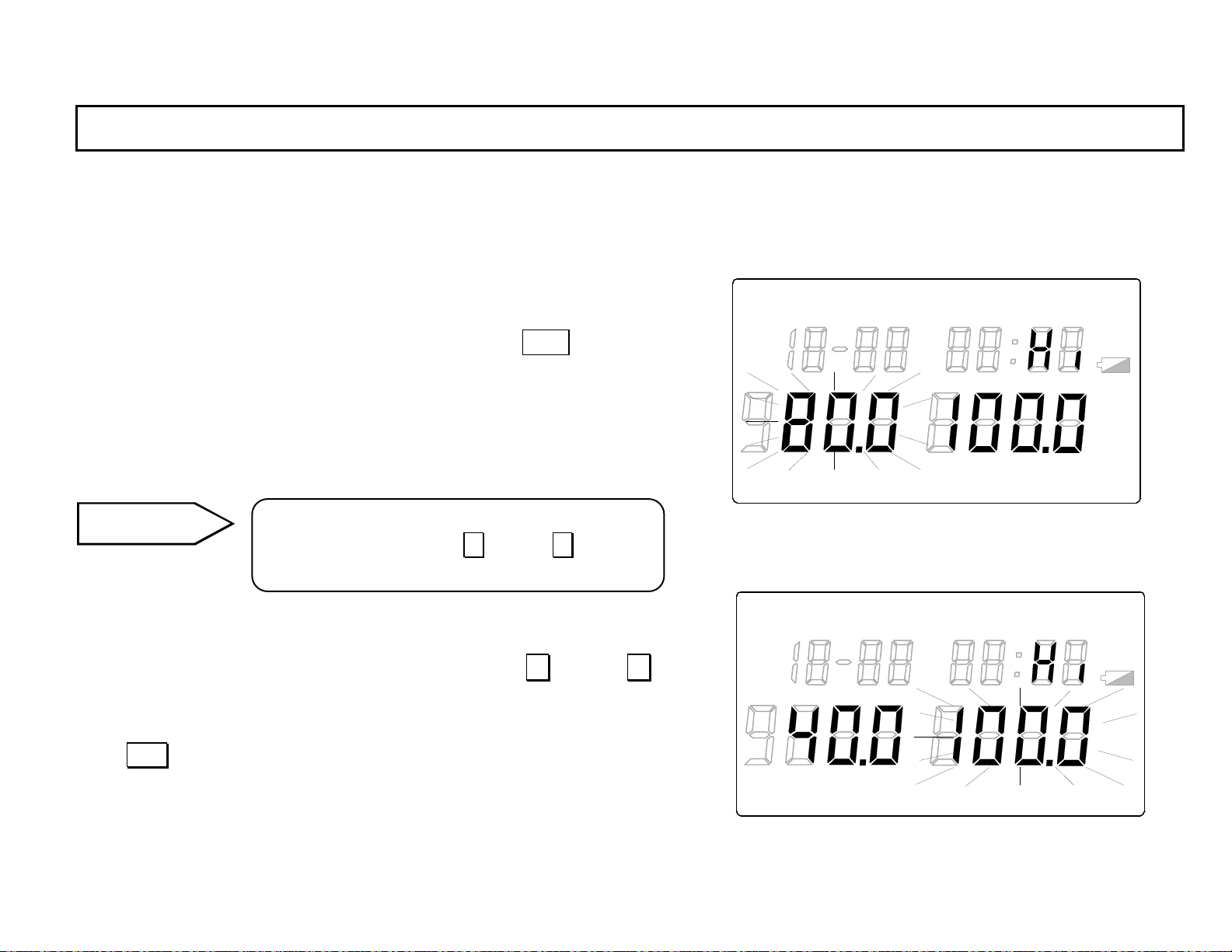
In the measurement unit selection mode (Ref. [5.3 Measurement unit
LOG TIME UNIT ALARM
READ
selection mode] in the separate instruction manual Vol. 1 <Basic
instructions> with “UNIT“ lit in the main marker, press DISP key to go
the high alarm set point programmi ng mode (“ALARM“ will light in the
main marker and “Hi“ will light in the sub display.). In the high alarm set
point programming mode, the temperature high alarm set point will flash in
°
℃
F
the main disp lay 1.
TERM
REP
INT REF
Reference
In the alarm set point programming mode, the
continuous pressing of ∧ key or ∨ key will
%RH
LOCK
°FH
H
℃
make the value change rapidly .
4.2.1 T emperature high alarm set point
Program the temperature high alarm set point by pressing ∧ key or ∨
key. The value changes in 0.1-increment (within the programming
range).
Press ENT key to retai n the programmed value. T he flas hing of t he temperature high alarm set point programmed will stop and then the humidity
high alarm set point will flash in the m ain display 2.
-20-
LOG TIME UNIT ALARM
READ
°
F
℃
TERM
REP
INT REF
LOCK
°FH
℃
%RH
H
Page 31
INST.No.INE-418-2P1CE
4. Parameter programming
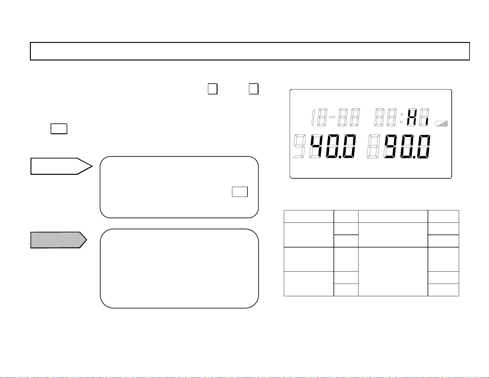
4.2.2 Humidity high alarm set point
Program the humidity high alarm set point by pressing ∧ key or ∨
key. The value changes in 0.1-increment (within the programming
range).
Press ENT key to retain the programmed value. The flashing of the hu-
midity high alarm set point programmed will stop.
Remarks
When the temperature high alarm set point is
only change d, the re tain ing o f the hum idity h igh
alarm set point programmed by pressing ENT
key is required.
LOG TIME UNIT ALARM
TERM
READ
REP
°
F
℃
INT REF
%RH
LOCK
°FH
℃
H
Unit Programming range Default
Caution
When the measurement unit (Ref. [5.3
Measurement unit selection] in the separate
instruction manual Vol. 1 <Basic instructions>)
is changed, the alarm set points programmed
will be initialized. Make sure to reprogram
the alarm set points.
-21-
Relative
humidity
temperature
º ºC 80.0 Temperature
ºF
%RH 100.0
ºC Dew point
ºF
-199.9 to 199.9
-199.9 to 199.9
180.0
Page 32
INST.No.INE-418-2P1CE
4. Parameter programming
4.3 Low alarm set po int
This is the programm ing mode f or the low alarm set point ap plied to the data stored in [1.2 Storing (data logging) mode].
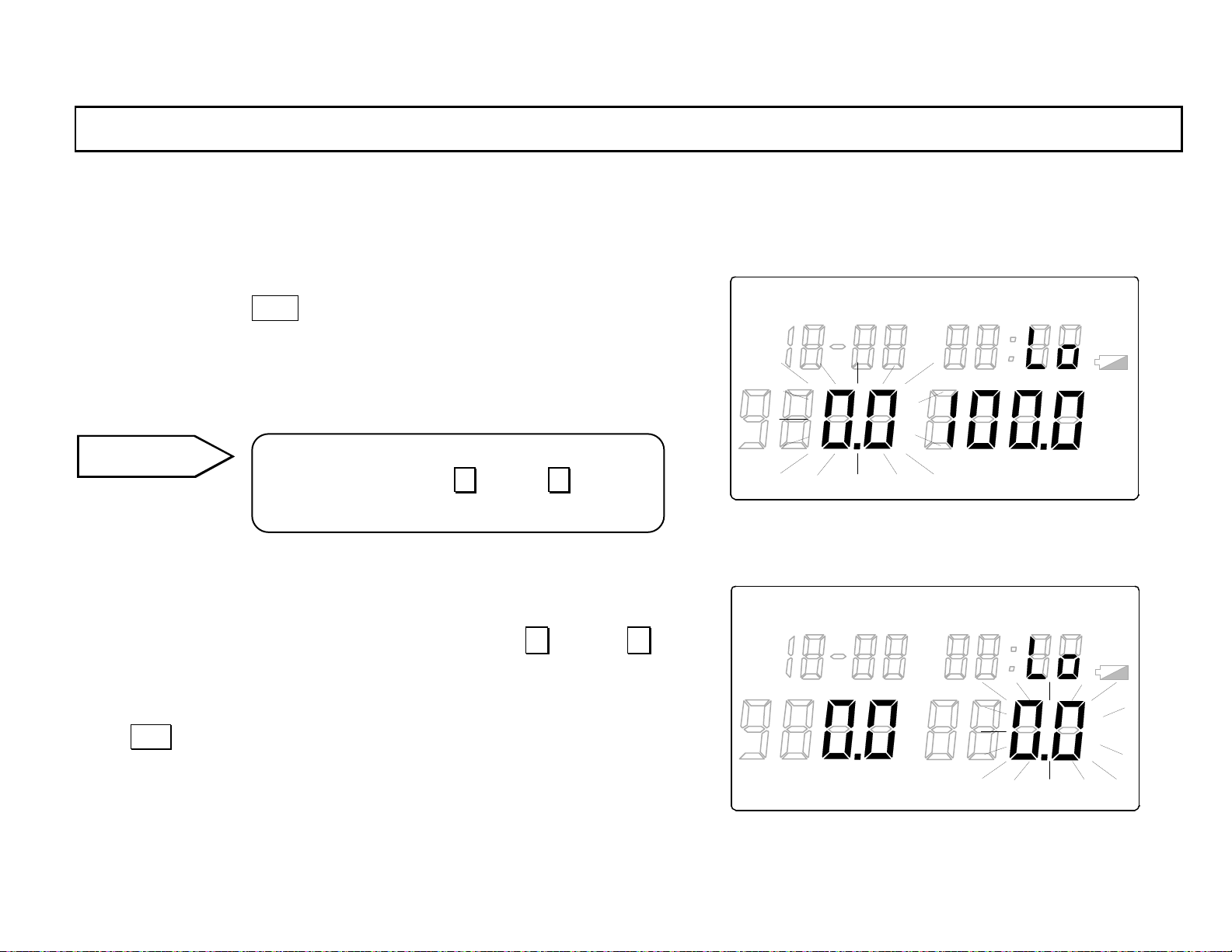
In the high alarm set point programming mode with “ALAR M“ lit in the
main marker, press DISP key to go to the low alarm set point
LOG TIME UNIT ALARM
programming mode (“A LA RM“ will light in the main marker and
“Lo“ w ill light in the sub display.). In the low alarm set point programm ing
READ
mode, the temperature low alarm set point flashed in the main display 1.
Reference
In the alarm set point programming mode, the
continuous pressing of ∧ key or ∨ key will
make the value change rapidly.
4.3.1 T emperature low alarm set point
Program the temperature lo w alarm set point by pressi ng ∧ key or ∨
key. The value changes in 0.1-increment (within the programming
range).
Press ENT key to retain the programmed value. The flashing of the
temperature low alarm set point programmed will stop and then the
humidity low alarm set point wi ll flash in the main display 2.
°
F
℃
TERM
LOG TIME UNIT ALARM
REP
READ
INT REF
°
F
℃
TERM
REP
INT RE F
%RH
LOCK
%RH
LOCK
°FH
℃
°FH
℃
H
H
-22-
Page 33
INST.No.INE-418-2P1CE
p
4. Parameter programming
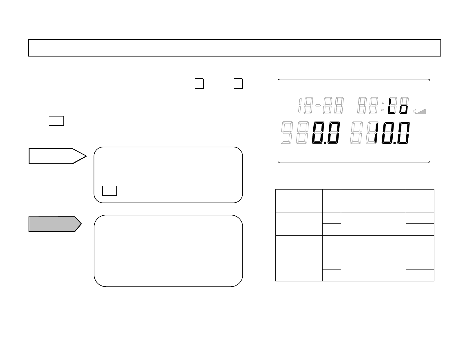
4.3.2 Humidity low alarm set point
Program the humidity low alarm set point by pressing ∧ key or ∨
key. The value changes in 0.1-increment (within the programming
range).
Press ENT key to retain the programmed value. The flashing of the
humidity low alarm set point programmed will stop.
Remarks
When the temperature low alarm set point is
only changed, the retaining of the humidity
low alarm set point programmed by pressing
ENT key is required.
Caution
Caution
When the measurement unit (Ref. [5.3
Measurement unit selection] in the separate
instruction manual Vol. 1 <Basic instructions>)
is changed, the alarm set points programmed
will be initialized. Make sure to reprogram the
alarm set
oints.
LOG TIME UNIT ALARM
TERM
READ
REP
°
F
℃
INT RE F
%RH
LOCK
°FH
℃
H
Unit Programming range Default
Relative
humidity
temperature
º ºC -40.0 Temperature
ºF
%R
H
ºC Dew point
ºF
-199.9 to 199.9
-199.9 to 199.9
-40.0
0.0
-23-
Page 34
INST.No.INE-418-2P1CE
4. Parameter programming
4.4 Automatic storage
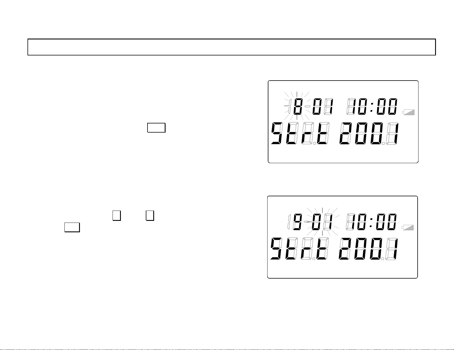
4.4.1 Sto rage st art t ime
This is the programming mode for the storage start time.
In the [4.3.2 Humidity low alarm setpoint] programming mode with
“ALAR M“ lit in the main marker, press DISP key to go t o the storag e
start time programming mode (“TERM“ will light in the main marker
and “Strt“ will light in the main di splay 1.). In the storage start time
programming mode, “month” will flash in the display of “month/day”.
4.4.1-1 Retaining of month
Select the month by pressing ∧ key or ∨ key .
By pressing ENT key, the month selected will be retained and “day” will
flash.
LOG TIME UNIT ALARM
READ
°
F
℃
TERM
LOG TIME UNIT ALARM
REP
READ
INT REF
°
F
LOCK
℃
TERM
REP
INT REF
LOCK
°FH
℃
%RH
°FH
℃
%RH
H
H
-24-
Page 35
INST.No.INE-418-2P1CE
4. Parameter programming
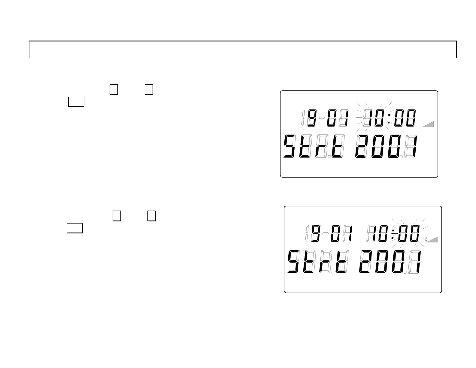
4.4.1-2 Retaining of day
Select the day by pressing ∧ key or ∨ key.
By pressing ENT key, the day selected will be retained and “hour” will
flash.
LOG TIME UNIT ALARM
READ
4.4.1-3 Retaining of hour
Select the hour by pressing ∧ key or ∨ key.
By pressing ENT key , the hour selected will be retained and “mi nute” will
flash.
°
F
℃
TERM
LOG TIME UNIT ALARM
REP
READ
INT REF
°
F
LOCK
℃
TERM
REP
INT RE F
LOCK
°FH
℃
%RH
°FH
℃
%RH
H
H
-25-
Page 36
INST.No.INE-418-2P1CE
4. Parameter programming
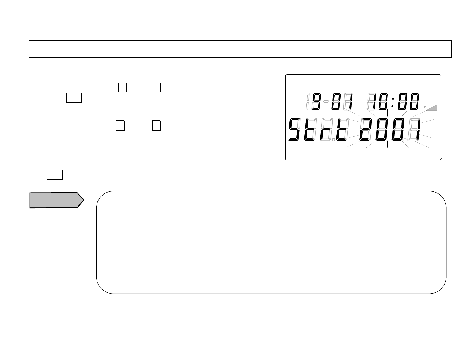
4.4.1-4 Retaining of minute
Select the minute by pressing ∧ key or ∨ key.
By pressing ENT key , the minute selected will be retained and “year” w ill flash.
4.4.1-5 Retai ning of year
Select the year by pressing ∧ key or ∨ key. (The year up to 2099 can be
selected.)
LOG TIME UNIT ALARM
READ
°
℃
F
%RH
°FH
℃
H
TERM
REP
INT RE F
LOCK
4.4.1-6 S toring of sto rage st ar t time
Press ENT key to retain the year selected. The flash ing of the year sele cted will stop and the storage start time programmed will be stored.
Caution
. When the storage start time is changed , make sure to reprogram the storage stop time.
If t he s t o ra g e stop tim e is n o t re prog ram med , it will b e th e sam e tim e a s the sto rag e star t tim e ch ang ed an d t he
automatic storage will be disabled.
. In addition, when the storage start time is changed, the storage repetition programmed in [4.4.3 Storage
repetition] w ill be in itialized. M ake sure to reprogr am the stor age repetit ion
. When the batteries are replaced, the storage start time will be initialized. Make sure to reprogram the storage
start time.
When the clock is changed, the storage start time will be the same time as the clock changed. Make sure to
reprogram the storage start time.
-26-
Page 37
INST.No.INE-418-2P1CE
4. Parameter programming
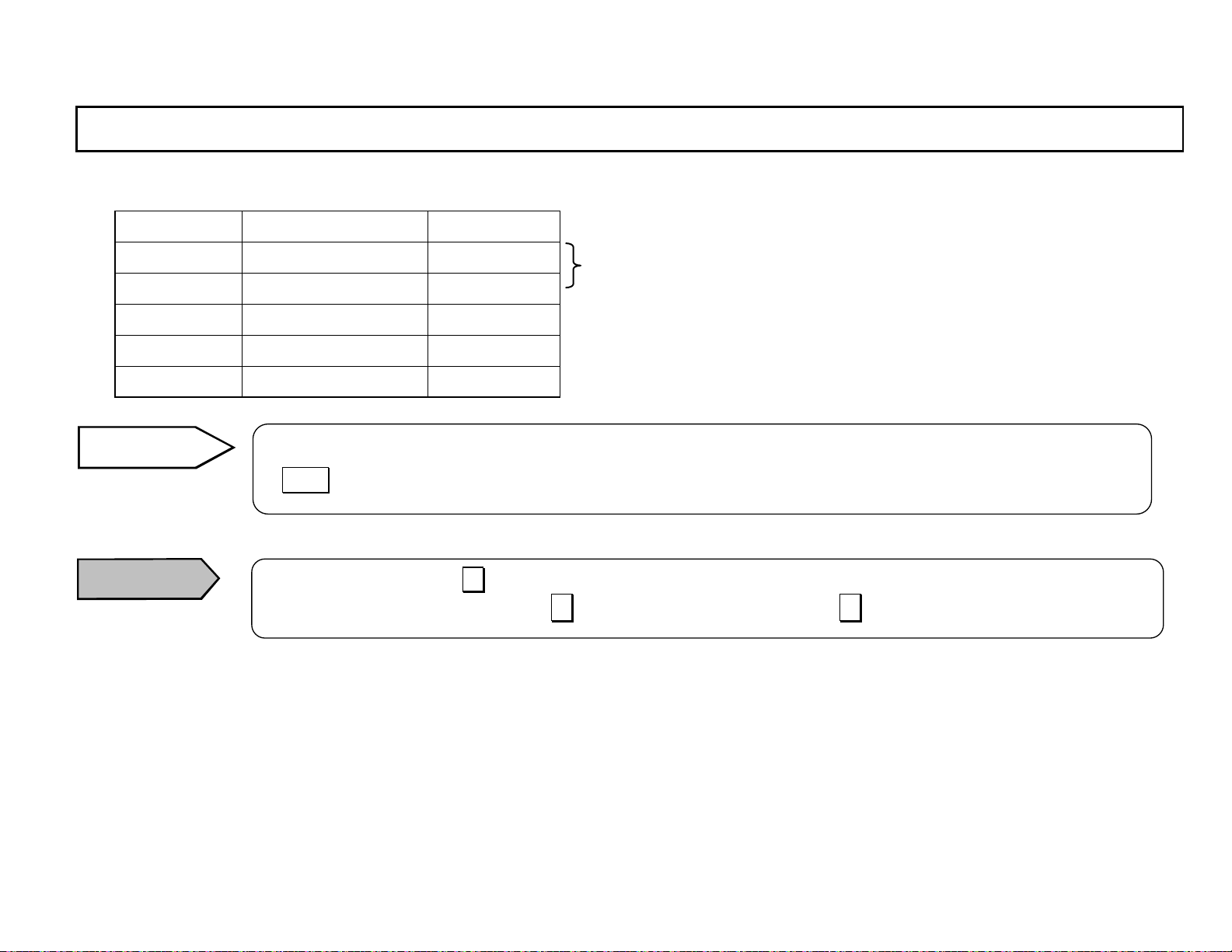
Programming range of storage start time
Programming range Default
Month * 1 to 12 1
Day * 01 to 31 01
Hour 0 to 23 0
Minute 00 to 59 00
Year 2001 to 2099 2001
Reference
Caution
*Leap years are supported.
The time is based on 24-hour clock system. Program 14-hour for PM2 and 22-hour for PM10.
If DISP key is pressed before the retaining of year, the programmed data before it will not be stored.
For the programmi ng by ∧ key, when the value reaches to the maximum value of the programming range, it will
not return to th e default va lue even if ∧ key is pressed continuously . Use ∨ key to decrease the value.
-27-
Page 38
INST.No.INE-418-2P1CE
4. Parameter programming
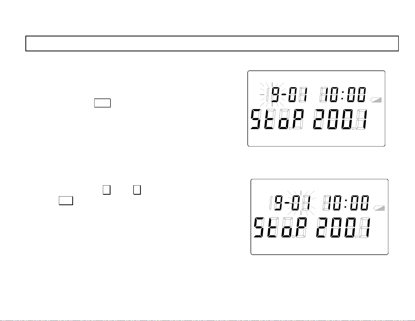
4.4.2 Storag e stop time
This is the programming mode for the storage stop time.
In the [4.4.1 Storage start time] programming mo de with “TERM“ lit in
the main marker, press DISP key to go to the storage stop time
programming mode (“S toP“ will light in the main display 1.). In the
storage stop time programming mode, “month” will flash in the display
of “month/d ay” .
4.4.2-1 Retaining of month
Select the month by pressing ∧ key or ∨ key .
By pressing ENT key, the month selected will be retained and “day” will
flash.
LOG TIME UNIT ALARM
READ
°
F
℃
TERM
LOG TIME UN IT ALARM
REP
READ
INT RE F
°
F
LOCK
℃
TERM
REP
INT REF
LOCK
°FH
℃
%RH
°FH
℃
%RH
H
H
-28-
Page 39
INST.No.INE-418-2P1CE
4. Parameter programming
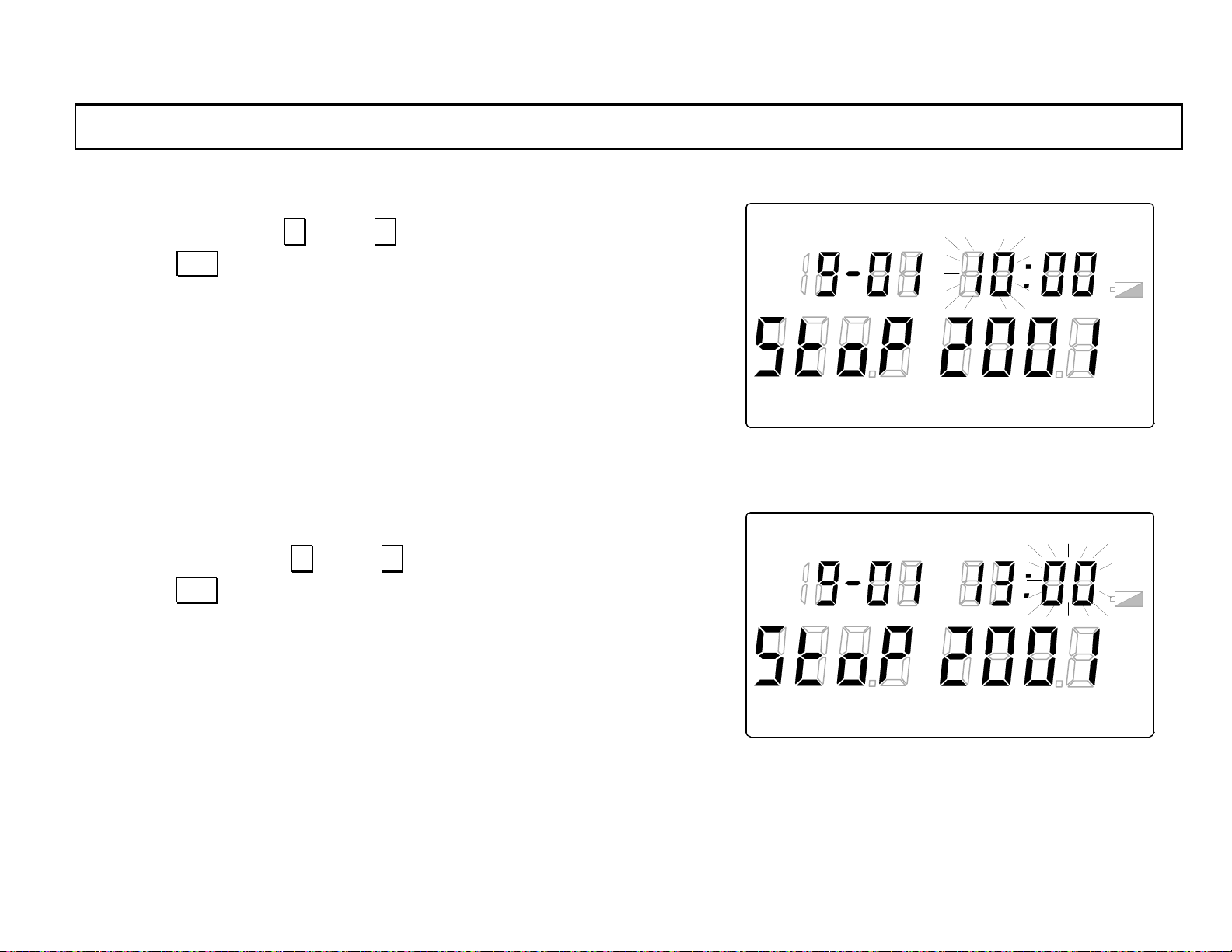
4.4.2-2 Retaining of day
Select the day by pressing ∧ key or ∨ key.
By pressing ENT key, the day selected will be retained and “hour” will
flash.
4.4.2-3 Retaining of hour
Select the hour by pressing ∧ key or ∨ key.
By pressing ENT key, the hour selected will be retained and “minute”
will flash.
LOG TIME UNIT ALARM
TERM
LOG TIME UNIT ALARM
READ
REP
READ
°
F
℃
INT RE F
°
F
℃
%RH
LOCK
%RH
°FH
℃
°FH
℃
H
H
TERM
REP
INT RE F
LOCK
-29-
Page 40
INST.No.INE-418-2P1CE
4. Parameter programming
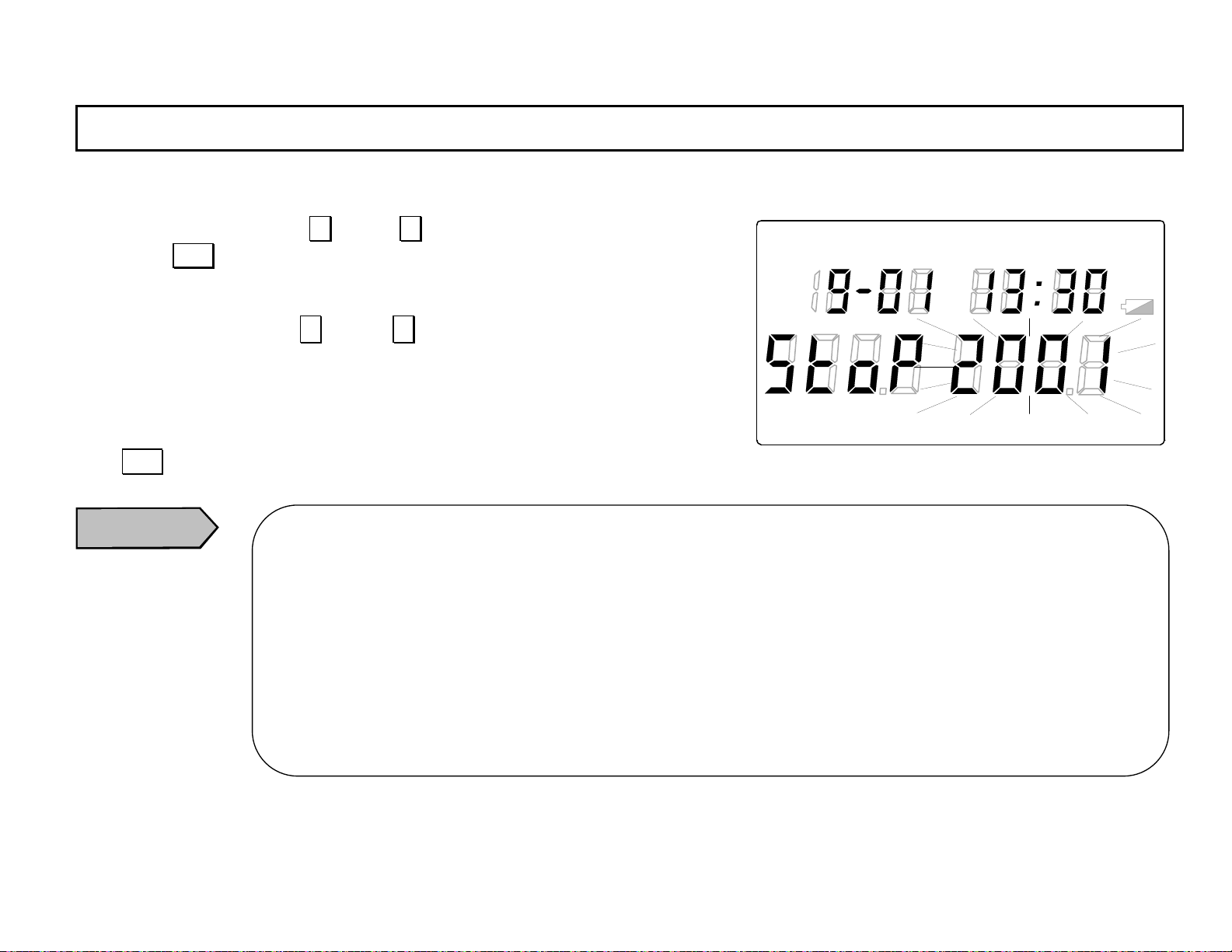
4.4.2-4 Retaining of minute
Select the minute by pressing ∧ key or ∨ key.
LOG TIME UN IT ALARM
READ
By pressing ENT key , the minute selected will be retained and “year” will flash.
4.4.2-5 Retai ning of year
Select the year by pressing ∧ key or ∨ key. (The year up to 2099 can be
°
selected.)
4.4.2-6 S toring of stor age stop time
TERM
REP
F
℃
INT REF
%RH
LOCK
Press ENT key to retain the year selected. The flashing of the year selected will stop and the storage stop time programmed will be stored.
Caution
When the storage start time is changed, make sure to reprogram the storage stop time.
If the storage stop time is not reprogrammed, it will be the same time as the storage start time changed and the
automatic storage will be disabled.
In addition, when the storage start time is changed, the storage repetition programmed in [4.4.3 Storage
repetition] w i l l be initialized. Make sure to reprogram the storage repetition
When the batteries are replaced, the storage start time will be initialized. Make sure to reprogram the storage
°FH
℃
H
start time.
When the clock is changed, the storag e start time will be the same ti me as the clock changed. Make sure to
reprogram the storage start time.
-30-
Page 41
INST.No.INE-418-2P1CE
4. Parameter programming
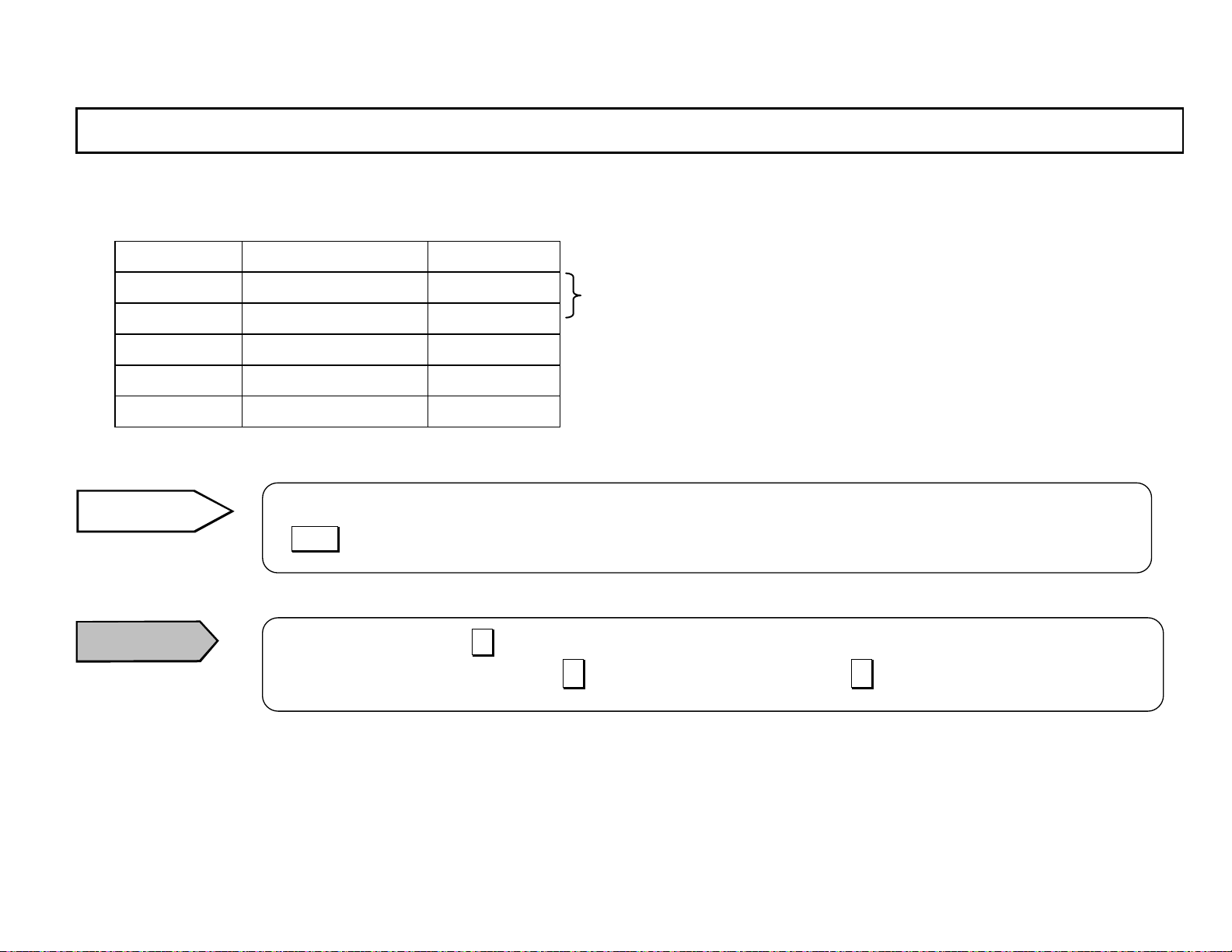
Programming range of storage stop time
Programming range Default
Month * 1 to 12 1
Day * 01 to 31 01
Hour 0 to 23 0
Minute 00 to 59 00
Year 2001 to 2099 2001
Reference
Caution
* Leap years are supported .
The time is based on 24-hour clock system. Program 14-hour for PM2 and 22-hour for PM10.
If DISP key is pressed before the retaining of year , the programmed data before it will not be stored.
For the programming by ∧ key , when the value reaches to the maximum value of the programming range, it will
not return to the default value even if ∧ key is pressed continuously. Use ∨ key to decrease the value.
-31-
Page 42
INST.No.INE-418-2P1CE
y
4. Parameter programming
4.4.3 Storage repetition
This is the programming mode for the storage repetition.
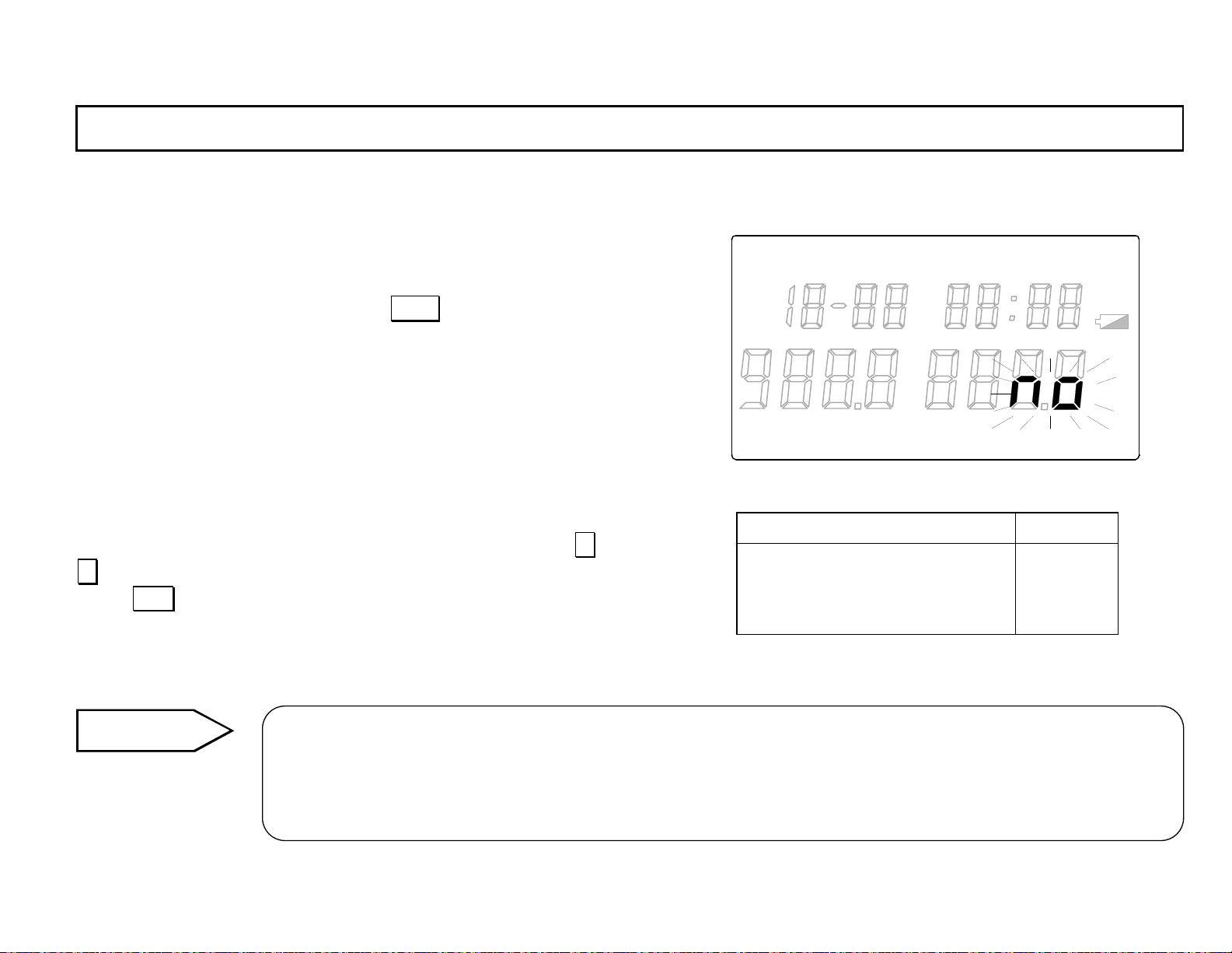
In the [4.4.2-6 Storing of storage stop time] programming mode with
“TERM“ lit in the main marker, press DISP key to go to the storage
repetition programming mode (“REP“ will light in the main marker.).
In the storage repetition programming mode, “no“ will flash in the
main display 2.
LOG TIME UN IT ALARM
READ
°
℃
F
%RH
°FH
℃
H
Select the desired repetition from “no“ (repetition disabled),
“dAY“ (every day) or “WE Ek“ (every week) by pressing ∧ key or
∨ key.
Press ENT key to retain the repetition selected. The flashing of the
repetition selected will stop.
Reference
If the period from the storage start time to the storage stop time is longer than 7 days, “no“ (repetition disabled) is onl
available.
If it is 24 hours or longer to 7 days or shorter, “no“ (repetition disabled) or “WEEk “(every week) is available.
If it is shorter th an 24 hou rs, no (repetition disabled), dA Y (every day) or WEEk (every week) is available.
-32-
TERM
REP
INT RE F
LOCK
Repetition Default
“no“
“dAY“
“WEEk“
Disable
Every day
Every week
“no“
Page 43
INST.No.INE-418-2P1CE
4. Parameter programming
4.5 T o talizing reference temperature/tot alizing direction
This is the programming mode for the totalizing reference temperature and
the totalizing direction.
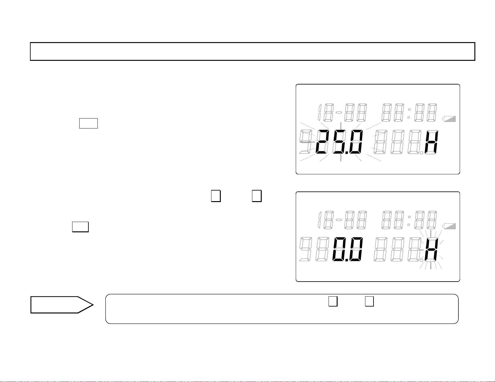
In the [1.5 Storing interval] programming m ode wi t h “INT“ lit in the main
marker, press DISP key to go to the totalizing reference temperature/totalizing dire ction progra mming mode (“REF“ will light in the main
marker and “H “ will light in the main display 2 .). In the to talizing re fer enc e
temperature/totalizing direction programming mode, “totalizing reference
temperature” will flash in the main display 1.
4.5.1 Totaliz ing referen ce temper ature
Program the totali zing refer ence temperat ure by pressing ∧ key or ∨
key. The value changes in 0.1-increment (within the programming
range).
By pressing ENT key, the totalizing reference temperature programmed
will be retained and “H“ will flash.
LOG TIME UNIT ALARM
READ
°
F
℃
TERM
LOG TIME UNIT ALARM
REP
READ
INT REF
°
F
LOCK
℃
TERM
REP
INT REF
LOCK
°FH
℃
%RH
°FH
℃
%RH
H
H
Reference
In the alarm set point programming mode, the continuous pressing of ∧ key or ∨ key will make the value
change rapidly .
-33-
Page 44
INST.No.INE-418-2P1CE
4. Parameter programming
4.5.2 Totaliz ing directio n
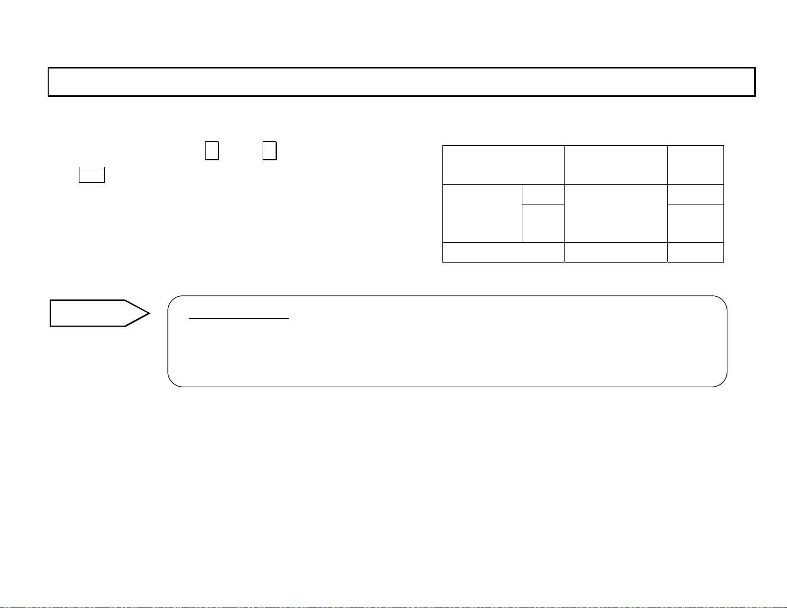
Select “H“ or “L“ by pressing ∧ key or ∨ key.
Press ENT key to retain the totalizing direction s elected. The flashing of
the totalizing direction selected w ill stop.
Reference
Totalizing dir ection
Select H when the measured temperature is higher than th e totaliz ing referen ce temperature.
Select L when the measured temperature is lower than the totalizing reference temperature.
For the details, refer to [ 3.2 <<Definition of totalized temperature>>].
Programming
range
ºC 25.0 Totalizing
referen ce
temperature
Totalizing direction H, L H
ºF
-199.9 to 199.9
Default
75.0
-34-
Page 45
INST.No.INE-418-2P1CE
4. Parameter programming
4.6 Auto-power-off
The auto-power-off function is for avoiding the comsumption of the
batteries. If no ke y is pressed for 1 minute, the cont inuous measurement
will automatically stop and the mode will move to the clock mode.
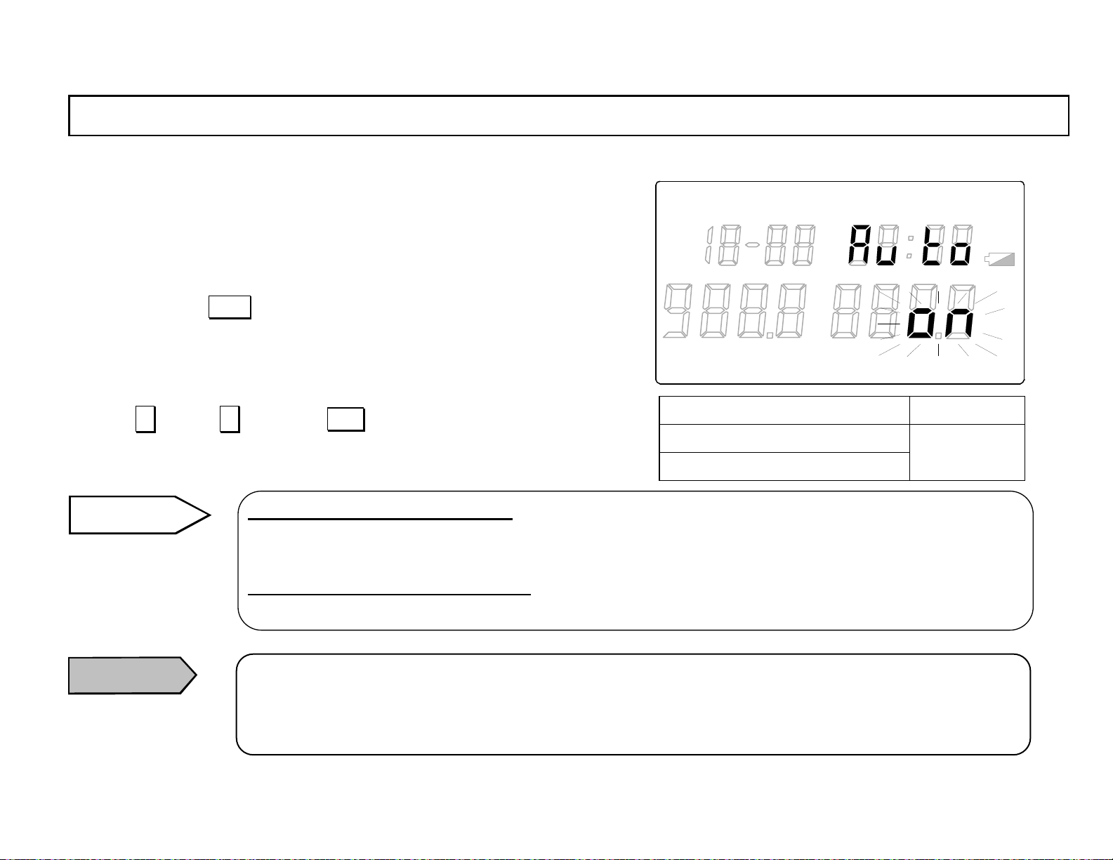
In the [4.5.2 T otalizing direction] programming mode with “REF “ lit in the
main marker, press DISP key to go to the auto-power-off selection mode
(“Auto“ will light in the sub display. ). In the auto-power-off selection
mode, “no“ (active) will flash in the main display 2.
For releasing the auto-power-off function, select “oFF“ (release) by
pressing ∧ key or ∨ key. Press ENT key to retain “oFF“ selected.
The flashing of “oFF“ will stop.
Reference
Auto-power-off function: on (active)
In the stored data reading mode and the parameter programming mode, i f no key is pressed for 1 minute, t he
continuous measurement will automatically stop and the mode will move to the clock mode.
Auto-power-off function; oFF (release)
The continuous measurement will continue and any mode will not move to the clock mode.
LOG TIME UN IT ALARM
TERM
READ
REP
°
F
℃
INT REF
%RH
LOCK
°FH
H
℃
Auto-power-off Default
“on “(active)
“oFF“ (release)
“on “
(active )
Caution
When the auto-power-off function is set to “oFF “ (release) and the continuous measurement is executed, the
batteries will be consumed very rapidly .
For the continuous measurement constantly executed, use the AC power adapter (RH32-AC110) sold
separately.
-35-
Page 46
INST.No.INE-418-2P1CE
4. Parameter programming
4.7 Instrument No.
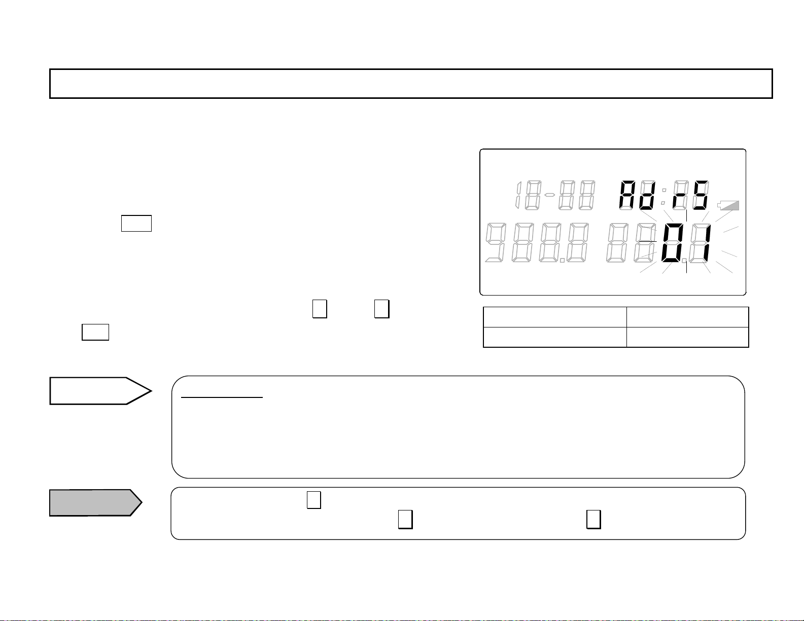
This is the programming m ode for number ing inst rument Nos. whe n multiple RH32-C2 are used.
In the [4.6 Auto-power-off] selection mode with “Auto“ lit in the sub
display, press DISP key to go to the in strument No. programmi ng mode
(“Adr S“ will light in the sub display.). In the instrument No. programm ing
mode, “01 “ will flash in the main display 2.
Select the instrument No. from 01 to 99 by pressing ∧ key or ∨ key.
Press ENT key t o retain the instru ment No. selected. T he flashing of
the inst rumen t N o. s e lect ed wil l sto p.
Reference
Instrument No.
For RH32-C2 (RS-232Ccommunications)
When multiple R H32-C2 are used, use the instrument No. for identifying the mete rs.
For RH32-C4 (RS-485communications)
LOG TIME UNIT ALARM
TERM
READ
REP
°
F
℃
INT RE F
LOCK
Programming range Default
01 to 99 01
°FH
℃
%RH
H
Caution
The instrument No. is used as an address in the communications.
For the programming by ∧ key, when the value reaches to the max imum value of the programming range,
it will not return to the default value even if ∧ key is pressed continuously. Use ∨ key to decrease the v alue.
-36-
Page 47
INST.No.INE-418-2P1CE
5. T roubleshooting
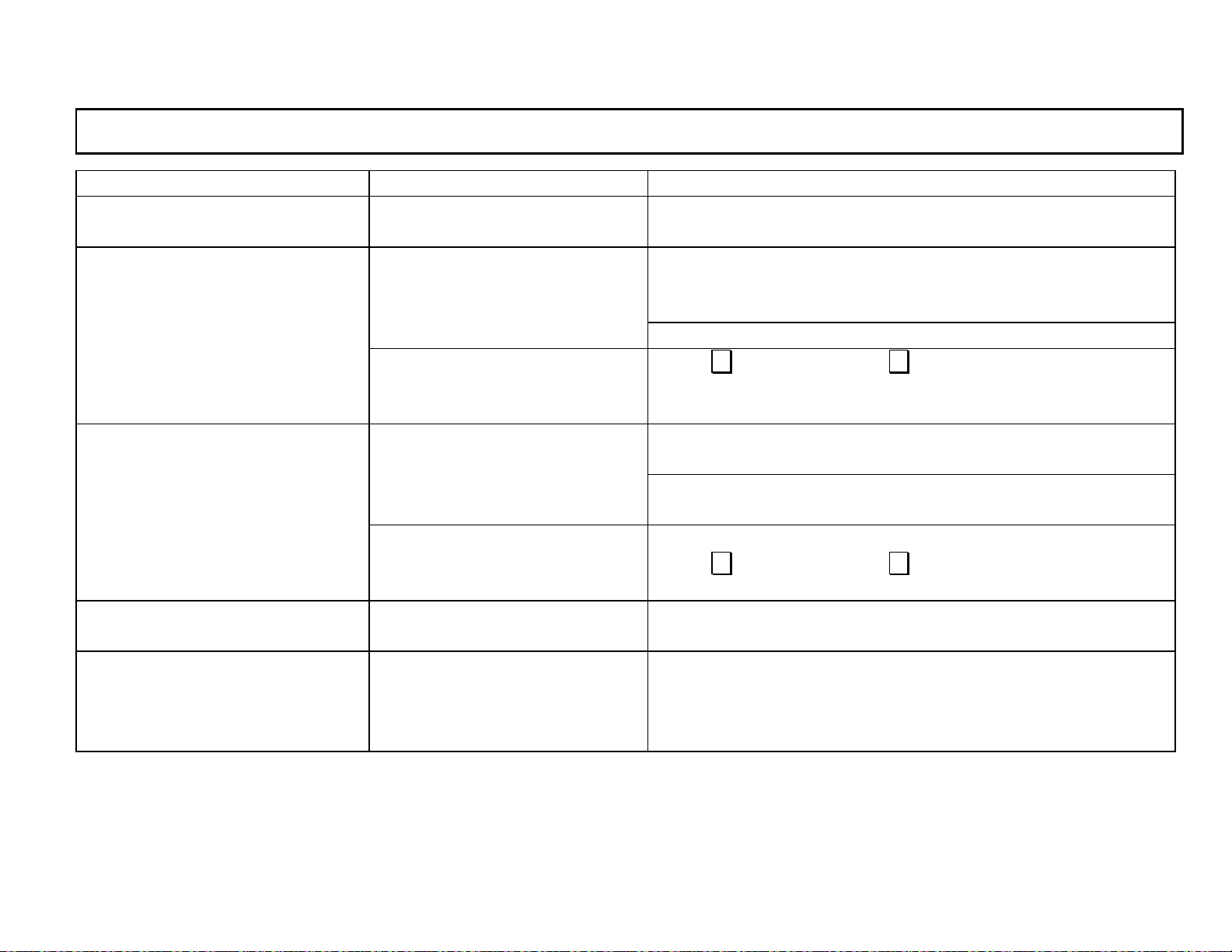
Phenomenon Content Countermeasure
1) “Er1“ is displayed in the main
display 1.
2) The humidity value in the main
display 2 is 100%RH.
(The dew-point temperature
value is same as the temperature
measured value.).
3) The humidity value in the main
display 2 is 0%RH.
(The dew-point temperature
value is --60ºC.).
4) “Er1“ is displayed in the main
display 2.
5) “Er2“ is displayed in the main
display 2.
Temperature measurement can’t
be executed.
100%RH has been measured in
the humidity measurement.
Interchangeability of the
temperature/humidity sensor has
not been obtained.
0%RH has been measured in the
humidity measurement.
Interchangeability of the
temperature/humidity sensor has
not been obtained.
Humidity measurement can’t be
executed.
In the dew-point temperature
display, the dew-point computatio n
is not possible due to abnormal
temperature data.
Check the connection of the temperature/humidity sensor. *1
Check if dew has been condensed in the temperature/humidity
sensor .
Measurement is possible after recovering from dew condensation.
Check the connection of the temperature/humidity sensor.
Press ∨ key while pressing ∧ key.
The humidity measurement from 0%RH is possible.
Check if an object is not in absolute dry condition.
Check the connection of the temperature/humidity sensor.
Press ∨ key while pressing ∧ key.
Check the connection of the temperature/humidity sensor. *1
If “Er1“ is displayed in the main display 1, chec k the connection of
the temperature/humidity sensor.
*1
*1
*1
*1 Refer to [7 . Replacem ent of tem peratur e/humidity se nsor] in the separ ate instruction manual Vol. 1 <Basic in struction s>.
*2 Refer to [5.1 Loading o f batteries] in the separate instruction manual Vol. 1 <Basic instructions>.
*1
*1
-37-
Page 48
INST.No.INE-418-2P1CE
5. T roubleshooting
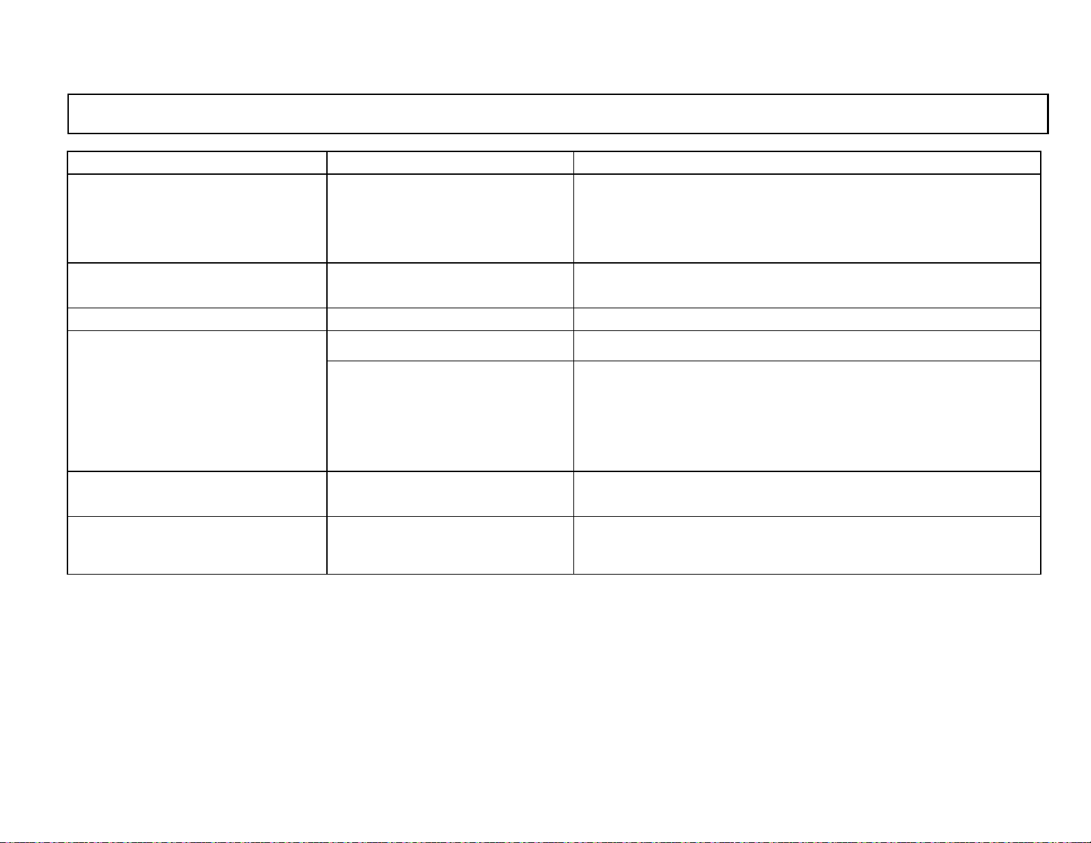
Phenomenon Content Countermeasure
The batteries are dead.
6) “Er4“ is displayed in the main
display. 2
7) Nothing including the clock is
displayed.
8) None displayed The batteries are dead Replace the batteries to new ones. *2
9) Automatic storage can’t be
executed
10) “oFL“ is displayed in the main
display 1.
If Er4 is still displayed after the
battery replacement, this meter
has been abnormal.
No power has been supplied.
Parameter not correct Check parameters including clock.
Memory is full.
Temperature measured value
overflowed
Replace the batteries to new ones
If “Er4“ is still displayed after the battery replacement, contact your
CHINO’s agent.
Replace the batteries to new ones.
1. Clear the memory. (Re f. [4.1 S tor ed data deletion ])
All stored data will be deleted by the stored data deletion.
2. By the data logging software package (sold separately),
program the storag e function to “Endless”. W hen the memory
becomes full (8000 data), a new data overwrite the oldest data.
Check the temperature measuring range.
Check the connection of the temperature/humidity sensor.
*2
*2
*1
11) “uFL“ is displayed in the main
display 1.
Temperature measured value
underflowed
Check the temperature measuring range.
Check the connection of the temperature/humidity sensor.
*1 Refer to [7. Replacement of temperature/humidity sensor] in the separate instruction manual Vol. 1 <Basic instructions>.
*2 Refer to [5.1 Load ing of batteries] in the separ ate instruction m anual Vol. 1 <Basic instructions >.
-38-
*1
 Loading...