

Page 1
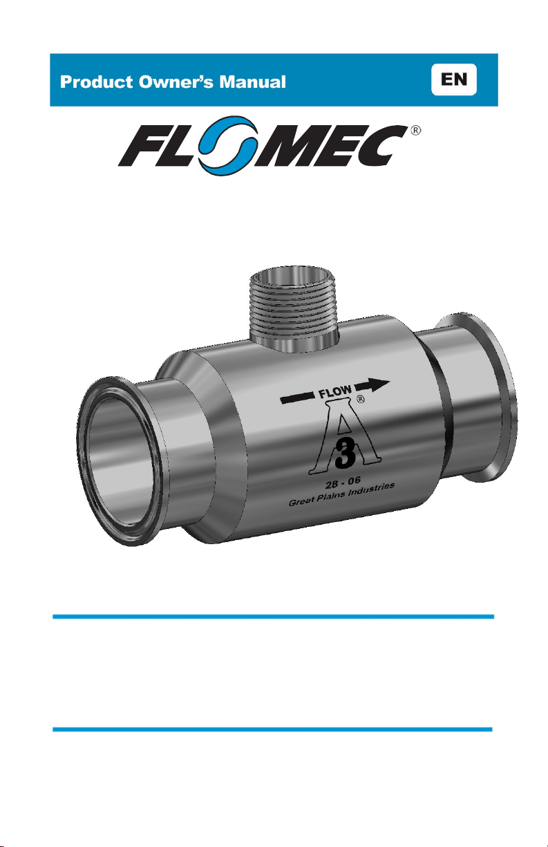
G-SERIES TURBINES
(3-A High Temperature Sanitary Models)
(GSCPS)
11/2021 921977-02 Rev. G
Page 2

To the owner…
Congratulations on receiving your FLOMEC® G-Series Sanitary Turbine.
We are pleased to provide you with a product designed to give you
maximum reliability and efficiency.
Our business is the design, manufacture, and marketing of liquid handling,
agricultural, and recreational products. We succeed because we provide
customers with innovative, reliable, safe, timely, and competitively priced
products. We pride ourselves in conducting our business with integrity and
professionalism.
We are proud to provide you with a quality product and the support you
need to obtain years of safe, depend- able service.
President
Great Plains Industries, Inc.
TABLE OF CONTENTS
General Information ---------------------------- 2
Installation ----------------------------------------- 4
Maintenance -------------------------------------- 5
Troubleshooting -------------------------------- 12
Troubleshooting Reference Guide --------- 15
Specifications ----------------------------------- 16
Service ------------------------------------------- 18
Warranty ----------------------------------------- 20
2
Page 3

GENERAL INFORMATION
This manual will assist you in installing and maintaining your FLOMEC G-Series
Sanitary Turbine. For best results, take the time to fully acquaint yourself with all
information about all components of your G-Series Sanitary Turbine. If you need
assistance, contact the distributor from whom you purchased your turbine.
Product Description
FLOMEC G-Series Sanitary Turbine flowmeters are volumetric flow measurement
devices. The moving fluid is used to turn a rotor, which is suspended in the flow
stream. The rotating speed of the rotor is proportional to the fluid velocity or
flowrate. As the blades from a spinning rotor pass by a magnetic sensor, an AC
voltage pulse is generated and transmitted to the readout instrument. Each pulse
is equal to a given volume of liquid; therefore “x” number of pulses are equal to a
gallon, litre, pound, barrel, etc.
Turbine Sizing
FLOMEC G-Series Sanitary Turbines are identified by the internal diameter of the
inlet and outlet.
Model 100 1 in. (6.7-67 GPM)
Model 100L 1 in. (6.7-67 GPM)
Model 150 1-1/2 in. (17.7-177 GPM)
Model 150L 1-1/2 in. (17.7-177 GPM)
Model 200 2 in. (33-330 GPM)
Model 200L 2 in. (33-330 GPM)
Turbine flowmeters should be sized in accordance to the actual flowrate and not
the process pipe size. For example, a process having a flowrate of 10-20 GPM in
a 1-1/2 in. process line requires Model 100 OR 100L turbine flowmeter.
Another important factor to take into consideration when sizing a turbine flowmeter
is instantaneous flowrate. This is extremely important when sizing a turbine
flowmeter where the volume is measured per hour or per day. For example, an
application where the total output is 500 barrels per day, occurring in a 5-hour
period; the recommended turbine flowmeter should be sized according to the
instantaneous flowrate:
(500 – 5) x 24 or 2,400 barrels per day
Thus, requiring a 1-1/2 inch turbine flowmeter.
3
Page 4

INSTALLATION
Turbine flowmeters are affected by both upstream and downstream process
configurations. Turbine flowmeters should always be installed with a minimum of
10 pipe diameters upstream and 5 pipe diameters downstream. The only exception
is the placement of the pumps, valves, etc., on the upstream end. When this
occurs, 20 diameters of straight pipe should be used. The direction of flow is
indicated by the arrow on the turbine. All turbine flowmeters are designed to
measure flow in only one direction.
Check the items below once the turbine flowmeter is installed in the process line.
This will ensure a successful start-up.
1. Before installing the magnetic sensor, make sure that it is functioning properly.
This can be accomplished by checking the ohm resistance. Refer to Checking
Magnetic Pickup in the Troubleshooting section.
2. If a magnetic pickup enclosure is used on a sanitary turbine, discard the seal
cap that is included with the unit. If no enclosure is used, install the magnetic
pickup and slip the seal cap over the magnetic pickup and threads on the
adapter.
NOTE: This is not applicable for units that use a low profile adapter.
3. Check the interconnection cable between the turbine flowmeter and readout
device. Refer to Checking the Cable Assembly section.
4. Make sure that the new or correct K-factor is entered into the readout device.
NOTE: The K-factor is printed on the turbine body. The calibration report included
with the product provides several points along the flow curve.
Initial Start-Up
Turbine flowmeters can be installed in the horizontal or vertical position. When
installing a turbine flowmeter in the vertical position, it is important that the direction
of flow be up through the turbine flowmeter.
A spool should be installed in place of the turbine flowmeter during initial start-up
of a new process line. The process line should be purged, thus eliminating any
solids contained in the line. Once this is completed, the spool can be removed and
the turbine flowmeter installed.
Whenever possible, use 20 straight pipe diameters upstream and down- stream of
the turbine flowmeter. The length of straight pipe upstream and downstream of the
turbine flowmeter can be reduced with the use of flow straighteners or
straightening vanes. A minimum of 10 straight pipe diameters upstream and 5
downstream are required.
NOTE: Control valves should always be installed downstream of the turbine
flowmeter.
The turbine flowmeter should be installed in a location where the process line will
remain full of liquid at all times. Otherwise, when the process line becomes empty
and a valve is opened, the high velocity fluid hitting the turbine flowmeter rotor can
cause severe damage.
4
Page 5
Reference:
Turbine
WARNING
When there is entrained air in the process line, an air eliminator should be used.
This entrained air causes air pockets and these air pockets will cause the rotor to
spin at a faster rate than liquid, thus resulting in in- correct readings, which results
in an overstatement of actual flowrate and volume. This condition can damage the
flowmeter.
In process lines where particulates are present, a filter/strainer should be used.
Refer to the table below for the recommended mesh size.
Flowmeter Size
1 inch 40
1-1/2 inch 18
2 inch 14
Mesh Size
MAINTENANCE
Cleaning Procedures
G-Series Sanitary Turbines are designed to be compatible with commercially
accepted methods of both CIP (Cleaned-In-Place) mechanical cleaning as well as
intermittent SIP (Steam-In-Place) cleaning methods.
If CIP or SIP cleaning methods are not available, manual COP (Cleaning-Out-ofPlace) methods can be used.
Care must be taken during system start-up, chemical cleaning, air purge or steamcleaning processes to ensure that the turbine rotor does not over speed as damage
can result to the rotor and/or bearing. Maximum allowable over range for G-Series
Sanitary Turbines is 125% of maximum rated flowrate for intermittent periods.
A minimum fluid velocity of 5 foot per second (1.5 meter per second) must be
maintained during the CIP process to ensure adequate cleaning.
The following flowrates are recommended by the 3-A Recommended Practices
605-XX to achieve 5 FPS or 1.5 MPS in the respective Sanitary Tube size:
Product and Solution Pipelines and Cleaning Systems Used in
Milk and Milk Product Processing Plants, Number 605-XX as
amended for procedures and recommended flowrates.
3-A Accepted Practices for Permanently Installed
O.D. I.D. FLOWRATE
1.0 in.
2.5 cm
1.5 in.
3.8 cm
2.0 in.
5.1 cm
.875 in.
2.22 cm
1.375 in.
3.50 cm
1.875 in.
4.75 cm
9.4 GPM
35.6 LPM
24 GPM
90.8 LPM
43 GPM
163 LPM
5
Page 6

Temperature limit for SIP cleaning is primarily limited by the temperature rating on
the magnetic pickup. If the pickup temperature rating will be exceeded during SIP
cleaning, remove it during the cleaning process or a higher temperature rated
pickup should be specified. Internal components of the G-Series Sanitary Turbine
must be limited to less than 285° F (140° C). The temperature and pressure rating
of gaskets and clamps used in the installation must also be taken into
consideration when determining cleaning parameters.
Minimum requirements for effective sterilization with SIP cleaning are to maintain
250° F (121° C) at the coldest point in the system for a minimum of 30 minutes.
This requires a minimum of 15.3 psig (106 kPa) saturated steam pressure. Normal
recommended maximums for SIP cleaning on G-Series meters is 285° F (140° C)
and 39 psig (269 kPa) saturated steam pressure.
Disassembling the Turbine
1. Disconnect the turbine flowmeter cable from the magnetic pickup. (Refer to
Figure 1.)
2. Remove the magnetic pickup.
3. Ensure that the process line is depressurized and empty prior to removal of the
turbine flowmeter. Remove the turbine flowmeter from the process line.
4. Using a small screwdriver or similar tool, insert it into the radius notch of the
retaining ring on the outlet end, pull away from the groove and up, removing
the retaining ring from outlet end of the turbine flowmeter. This will allow the
rear support assembly and rotor to slide out of the turbine flowmeter body.
5. Remove the rear support assembly and rotor assembly before proceeding to
remove the front support.
NOTE: To remove the front support at the inlet end of the turbine flowmeter,
repeat the previous retaining ring and support removal operation.
6. Once the turbine flowmeter is taken apart, inspect the turbine flowmeter body
for signs of wear or defects. The body bore should be smooth and show no
evidence of wear.
NOTE: Do not install a new replacement kit into a turbine flowmeter body that
shows significant signs of wear.
7. Examine the rotor assembly for broken and/or bent blades. Remove any
foreign matter.
8. Examine the supports for signs of deterioration, such as wear marks and/or
burrs along the outer edge of the support vanes.
9. When the rotor assembly or the supports show any sign of deterioration, a new
replacement kit should be installed. Do not install a new replacement kit into a
defective turbine flowmeter body.
6
Page 7
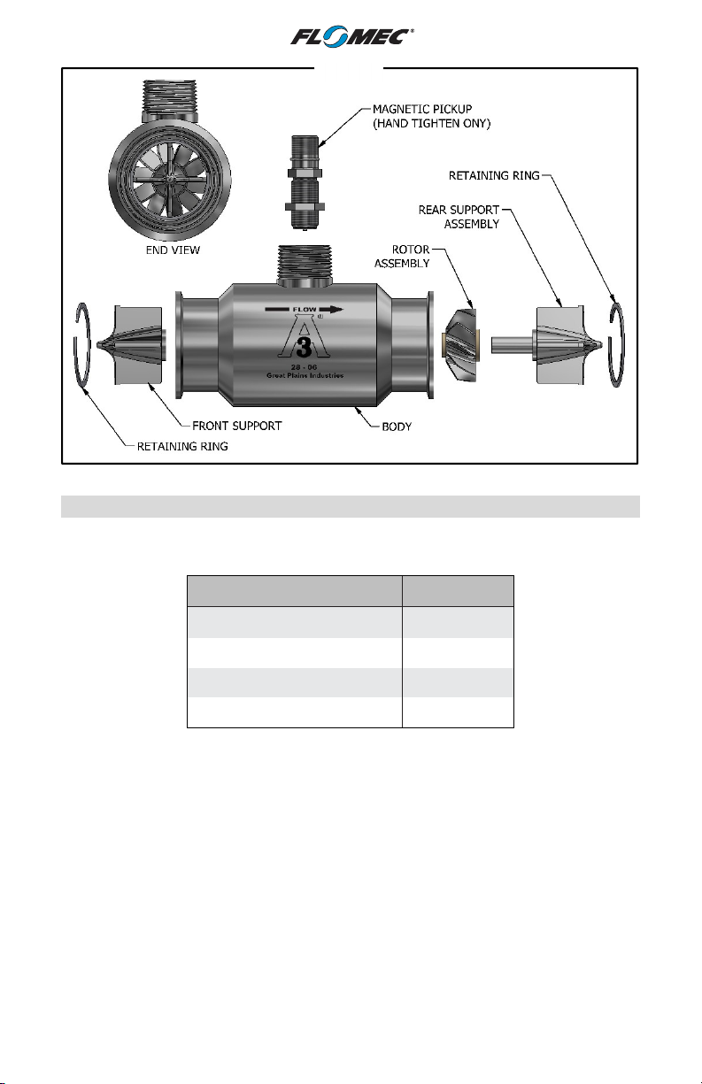
Figure 1
Replacement Kits
A replacement kit is comprised of all the internal component parts within the turbine
flowmeter. A replacement kit consists of the following:
Parts Description Quantity
Rotor Assembly 1
Support (Front) 1
Support Assembly (Rear) 1
Retaining Ring 2
FLOMEC Sanitary Turbine supports are not identical in design. The rear support
assembly has a shaft that supports the rotor; the front support does not.
Notice that the direction of flow is displayed on the body of the turbine flowmeter.
This is important when installing the supports and rotor and it also denotes the
direction in which the turbine flowmeter was calibrated.
1. Install the front support placing a vane between the notches in the turbine
flowmeter body. Install a retaining ring to keep the support in place.
2. Place the rotor assembly on the shaft of the uninstalled rear support assembly.
NOTE: FLOMEC Sanitary Turbine rotors are tapered on one end. The tapered end
should be installed facing the front support (see Figure 1).
7
Page 8
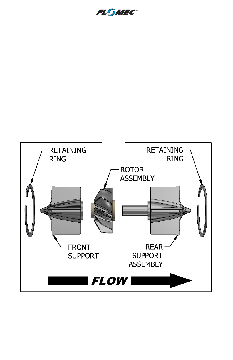
3. Hold the turbine flowmeter body with the rear (outlet) end down, and slide the
rotor assembly and rear support assembly into the turbine flowmeter body.
Make sure the vane is placed between the notches.
4. Once the rear support assembly is in place, install the retaining ring.
5. Blow into the turbine flowmeter to ensure the rotor spins freely.
NOTE: Installation of the replacement kit is complete and the turbine flowmeter
can be reinstalled into the process line.
6. Install the magnetic pickup. HAND TIGHTEN ONLY.
NOTE: Be sure to use the proper magnetic pickup, cable and connector for the
application.
7. Enter the new K-factor supplied with the replacement kit into the electronic
readout device. (Refer to the calibration report.)
NOTE: All internal replacement kits are factory calibrated and are supplied with a
five point calibration certificate.
Single Post Design Replacement Kit for FLOMEC G-Series Sanitary Turbines
Figure 2
8
Page 9
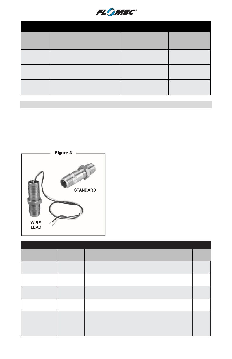
Magnetic
Cable
Replacement Kits for Sanitary Turbine Flowmeters (GSCPS)
Size
1 in. 6.7 - 67 GPM
1-1/2 in. 17.7 - 177 GPM
2 in. 33 - 330 GPM
Flow Range
(Gallons Per Minute)
Model Part No.
GSCPS-100
GSCPS-100L
81008074
GSCPS-150
GSCPS-150L
81508074
GSCPS-200
GSCPS-200L
82008074
Magnetic Pickups
FLOMEC offers two types of magnetic pickups: Standard and Wire Lead. (See
Figure 3.)
When choosing a magnetic pickup, the turbine meter and electronics are generally
already known. Electronics can be either Local or Remote. Remote electronics
include FLOMEC Remote Displays or output to customer-supplied equipment.
Follow the next three steps when choosing a magnetic pickup.
1. Select your size: 1 in., 1-1/2 in., or 2 in.
2. Choose Local or Remote/Output.
• Local uses a wire lead pickup.
• Remote/Output requires a connector.
3. Choose either Sine Wave or Square
Wave as your signal type.
• Sine Wave does not require external
power for the sensor, and can be used
with battery powered displays.
• Square Wave requires external power
to power the sensor.
Selection Guide for 1 in. 1-1/2 in., 2 in. Turbine Meters
Pickup Type
Wire Lead
Standard
Standard 81001000
Herm/High
Temp.
High Temp.
Standard
Part No. Application
81003000
Meter mount electronics. Temperature
range: -100°F to +250°F. Sine wave output.
Remote mount electronics. Temperature
range: -100°F to +250°F. Sine wave output.
81002000
81007000
Remote mount electronics. Temperature
range: -450°F to +258°F. Sine wave output.
Remote mount electronics. Temperature
range: -450°F to +800°F. Sine wave output.
Type
None
S
H or T
H or T
Remote mount electronics. Temperature
Active Digital 81004000
range: -40°F to +248°F. Square wave, open
collector output, 5-32 VDC required. Signal
D
output: 0-10V, NPN.
9
Page 10
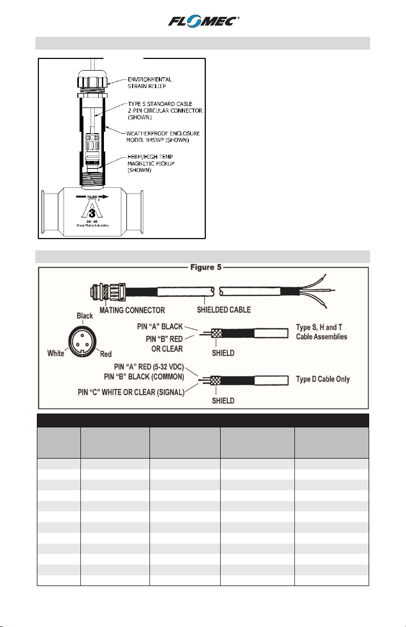
Type “S”
Type “D”
Type “H”
Type “T”
8 inch
5 feet
10 feet
15 feet
20 feet
25 feet
30 feet
40 feet
50 feet
75 feet
100 feet
125 feet
Magnetic Pickup Enclosures
Figure 4
Cable Assemblies (Connector Included)
Cable Length Selection Guide
Cable
Length
Standard
(2 Conductor)
Digital or RF
(3 Conductor)
83001001 83002001 83003001 83004001
83001005 83002005 83003005 83004005
83001010 83002010 83003010 83004010
83001015 83002015 83003015 83004015
83001020 83002020 83003020 83004020
83001025 83002025 83003025 83004025
83001030 83002030 83003030 83004030
83001040 83002040 83003040 83004040
83001050 83002050 83003050 83004050
83001075 83002075 83003075 83004075
83001100
83001125
Pickup Enclosures are optional on GSeries Sanitary Turbine Meters.
Choose from two versions of
weatherproof pickup enclosures (see
Figure 4):
• Model N4AWP - Part No. 80001101,
Zinc Plated Steel
• Model N4SWP - Part No. 80001105,
316 Stainless Steel
Water Resistant
10
(2 Conductor)
Hi-Temperature
(2 Conductor)
Page 11
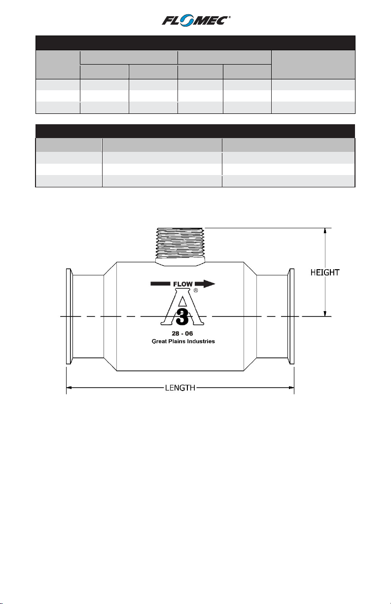
Gallons
Per Minute
Litres
Per Minute
LOW RANGES
Size
1 in.
1-1/2 in.
2 in.
Min. Max. Min. Max.
6.7 67 25.2 252
17.7 177 67.0 670
33 330 124.9 1249
DIMENSIONS
Size
1 in.
1-1/2in.
2 in.
Height Length
2.75 3.562
3.00 4.594
3.25 6.063
Dimensions are provided in inches.
(For optional low profile models, subtract 1 inch from height.)
Frequency Output
100 - 1000 Hz
100 - 1000 Hz
100 - 1000 Hz
11
Page 12
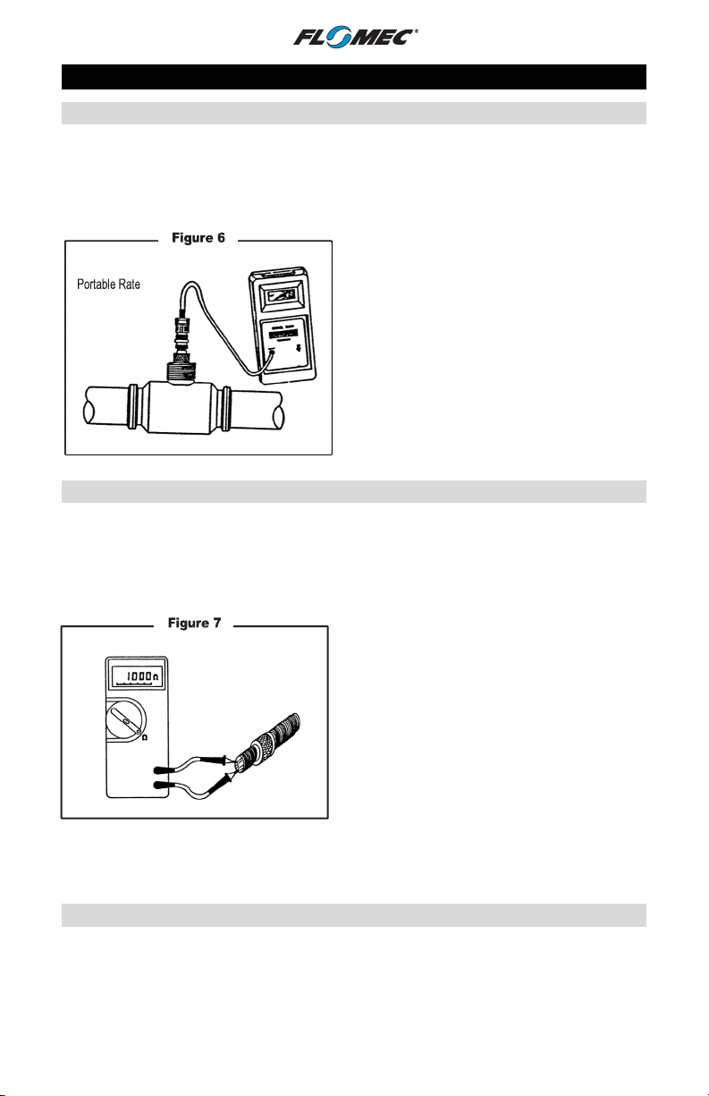
TROUBLESHOOTING
Locating the Problem
To determine the location of the problem, whether it is occurring at the turbine
flowmeter or at the electronic readout device, disconnect the cable assembly from
the magnetic pickup and connect the cable from the portable rate indicator onto
the magnetic pickup. (Refer to Figure 6.)
Hand-held
Indicator
Checking the Magnetic Pickup
To determine the status of a hermetically sealed, two-wire lead, or standard
magnetic pickup, simply remove it from the turbine flowmeter, and using an ohm
meter, measure the ohm resistance by placing the leads of the ohm meter on each
pin of the magnetic pickup. (Refer to Figure 7.)
NOTE: It is recommended that the ohm resistance be measured before installing
a used magnetic pickup.
The portable rate indicator will display the
instantaneous rate of flow through the
turbine flowmeter. If the rate displayed is
equal to the rate of the process, then
both the magnetic pickup and the turbine
flowmeter are operational. The problem
will be located in either the cable
assembly or the electronic readout
device
When there is no rate displayed on the
portable rate indicator, the problem may
be caused by a defective magnetic pickup
or turbine flowmeter.
If the ohmmeter reads 1400 ohms ±20%,
then the magnetic pickup is good and
should NOT be replaced. If the ohmmeter
reads less than 1000 ohms, install a new
magnetic pickup. DO NOT throw the old
magnetic pickup away. Failure of the
magnetic pickup may have been caused
by moisture trapped inside. In some cases
when the magnetic pickup is allowed to
dry, it has become completely functional
and can be reused. When the ohmmeter
reads in excess of 1700 ohms, the
magnetic pickup is defective and should
be discarded.
Checking the Turbine Flowmeter
Once it has been determined that the magnetic pickup is functional and there is no
output displayed on the portable rate indicator, it can be concluded that the
problem lies within the turbine flowmeter. Remove the turbine flowmeter from the
process line. DO NOT remove the internals at this time.
12
Page 13

Visually inspect the internals of the turbine flowmeter. Check for particulates and/or
foreign objects, which may have lodged between the rotor and the body. In the
event an object is detected, simply remove the retaining ring on the outlet side of
the turbine flowmeter and remove the support and rotor assembly. Once the
turbine flowmeter parts are free from any foreign matter, reassemble.
NOTE: Always ensure that a support vane is installed between the indention marks
on the body.
Upon completion, verify the rotor spins freely, reinstall the turbine flowmeter into
the process line.
If there are no signs of particulates or any other foreign matter obstructing the rotor,
try blowing into the turbine flowmeter. If the rotor does not spin freely, insert a thin
screwdriver or similar tool, gently so as not to damage any of the rotor blades, and
turn the rotor.
There may be another cause for the rotor to drag or stop, such as incorrect bearing
material used for the application. For example, non-compatibility of the bearing
material with the process liquid, bearing material may not withstand the
temperature of the application, etc. When there is uncertainty with respect to the
selection of bearing material for a given application, contact GPI.
Before installing a new replacement kit, inspect the turbine flowmeter body for wear
and damage. By placing your finger inside the turbine flowmeter body, feel for any
signs of wear such as grooves, ridges, irregular spots. If such signs are evident, it
is a strong possibility that the turbine flowmeter body is damaged and the
installation of a new replacement kit is NOT recommended.
When a new replacement kit is installed inside a damaged turbine flowmeter body,
the internals will be ruined after a short period of operation and will have to be
discarded. In the event it is uncertain whether the turbine flowmeter body is
functional, it should be sent to GPI so the I.D. dimension of the turbine flowmeter
body bore can be checked. If it is found to be within tolerance, a new set of internals
will be installed. This will eliminate the possibility of using and/or discarding a
turbine flowmeter that shows signs of wear.
NOTE: A good turbine flowmeter body should have a smooth inner bore free of
wear signs.
If it is determined that the turbine flowmeter body is in good condition, install a
new replacement kit and reinstall the turbine flowmeter into the process line.
Checking the Cable Assembly
This can be accomplished with the aid of a frequency oscillator. Simply plug the
cable assembly with the mating connector end that is located at the turbine
flowmeter into the frequency oscillator. The frequency oscillator will simulate the
output of a turbine flowmeter. If an output is displayed on the electronic readout
device, then the cable assembly is good.
In the event an output is not displayed, disconnect the frequency oscillator from
the cable assembly and connect the cable supplied with the frequency oscillator
directly to the electronic readout device, the same as you would a turbine
flowmeter cable assembly. (Refer to Figure 8.)
13
Page 14
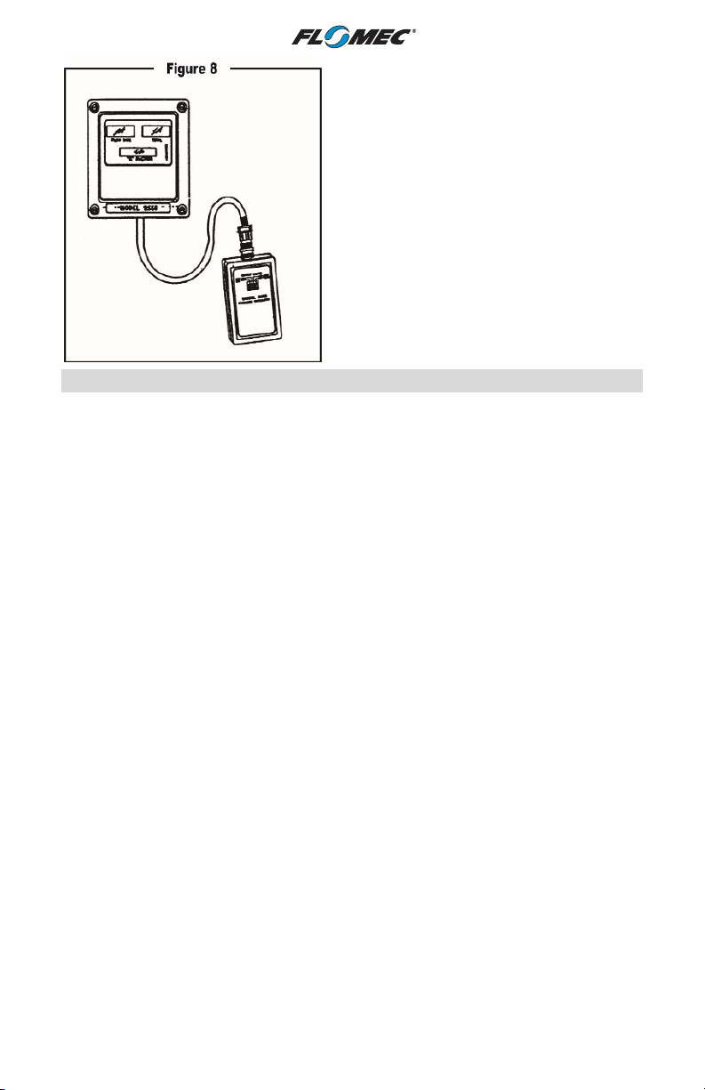
When the frequency oscillator is
connected and an output is displayed on
the electronic readout device, this
indicates that the turbine flowmeter cable
assembly is defective and should be
replaced. If no output is displayed, the
turbine flowmeter cable assembly is good
and the problem lies within the electronic
readout device.
Checking the Electronics
Using the frequency oscillator and the cable that is supplied, connect it to the
electronic readout device, the same as you would a turbine flowmeter cable
assembly. Once the frequency oscillator is connected, if no output is displayed on
the electronic readout device, check to ensure that the power is on, the fuses are
good, and the correct K-factor is dialed/programmed into the electronic readout
device. After verification of these items, if there is still no output displayed and/or
registered, then the manufacturer of the electronic readout device should be
consulted.
14
Page 15

Symptom
Probable Cause
Solution
way down into the turbine
tighten
rotor in accordance with the
Troubleshooting Reference Guide
No output is
displayed or
registered
More volume/
output than
displayed or
registered.
Less volume/
output than
displayed or
registered.
Defective magnetic pickup Refer to the Checking the
Foreign matter obstructing the
turbine flowmeter rotor
Defective turbine flowmeter
internals
Defective turbine flowmeter
cable assembly
Defective electronic/readout
device
Rotor may drag due to foreign
matter obstruction
Magnetic pickup not screwed
down all the way into the
turbine flowmeter body,
causing it not to detect all the
rotor blades as they pass.
Turbine flowmeter installed
backwards.
Turbine flowmeter rotor
installed backwards.
K-factor is too high in
electronic/readout device.
Caused by entrained air in the
process line.
K-factor is too low in
electronic/readout device.
Magnetic Pickup section.
Refer to the Checking the
Turbine Flowmeter section.
Refer to the Checking the
Turbine Flowmeter section.
Refer to the Checking the
Cable Assembly section.
Refer to the Checking the
Electronics section.
Refer to the Checking the
Turbine Flowmeter section.
Screw the magnetic pickup all
the
flowmeter body. Handonly.
Install the turbine flowmeter in
accordance with the process
flow direction.
Install the turbine flowmeter
process flow direction.
Verify K-factor used. K-factor
should be decreased.
Install an air eliminator
upstream of turbine flowmeter.
Verify K-factor used. K-factor
should be increased.
15
Page 16
SPECIFICATIONS
Accuracy *
Linearity *
Repeatability *
Response Time:
1 in., 1-1/2 in. & 2 in
Frequency Output:
1 in, 1-1/2 in. & 2 in.
Voltage Output:
1 in., 1-1/2 in., & 2 in
Maximum Overage
Operating Temperature
Standard Materials of Construction
Housing 316 Stainless Steel
Rotor Nickel Plated CD4MCu Stainless Steel
Shaft 316 Stainless Steel
Rotor Supports 316 Stainless Steel
Sleeve/Thrust Bearing PEEK
Retaining Rings 300 Series Stainless Steel
* Data based on water calibration @ 77°F (25°C).
±0.5% of the true flow at any point within the
linear range of the turbine flowmeter.
±0.5% of the mean K- factor throughout the
linear range.
±0.1% of the indicated flow throughout the
linear range.
2-5 milliseconds for step change in flowrate.
100 - 1000 Hz (Over the linear range)
Approx. 100 mV @ 100 Hz to
1.0 Volt (r.m.s.) @ 1000 Hz
Up to 125% of maximum flowrate for
intermittent periods.
-100° F to +225° F
(-70° C to +107° C)
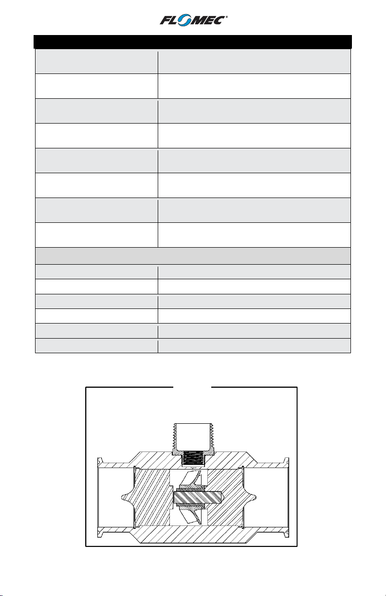
Figure 9
Materials of Construction
16
Page 17
GPM =
Hz x 60
Hz =
GPM x K
-
factor
K-factor =
Hz x 60
FLOW RELATED FORMULAS
Pulses Per Litre = K-factor
K-factor
60
GPM
3.785
Pulses Per Barrel = K-factor x 42
Pulses Per Cubic Meter = K-factor
. .003785
Pulses Per Pound = K-factor
Pounds Per Gallon
GPM = Pounds Per Hour
500 x S.G.
BPH = Barrels Per Hour GPS = Gallons Per Second
BPD = Barrels Per Day GPD = Gallons Per Day
BPM = Barrels Per Minute GPM = Gallons Per Minute
CFM = Cubic Feet Per Minute
Pounds Per Hour = 500 x S.G. x GPM
Pounds Per Gallon = S.G. x 8.33 (Water)
BPH = GPM x 1.42857
BPD = GPM x 34.286
BPM = GPM x 0.238
GPS = GPM x .01666
GPD = GPM x 1440.0
GPM = BPD x .029167
GPM = BPH x 0.7
CFM = GPM x .13368
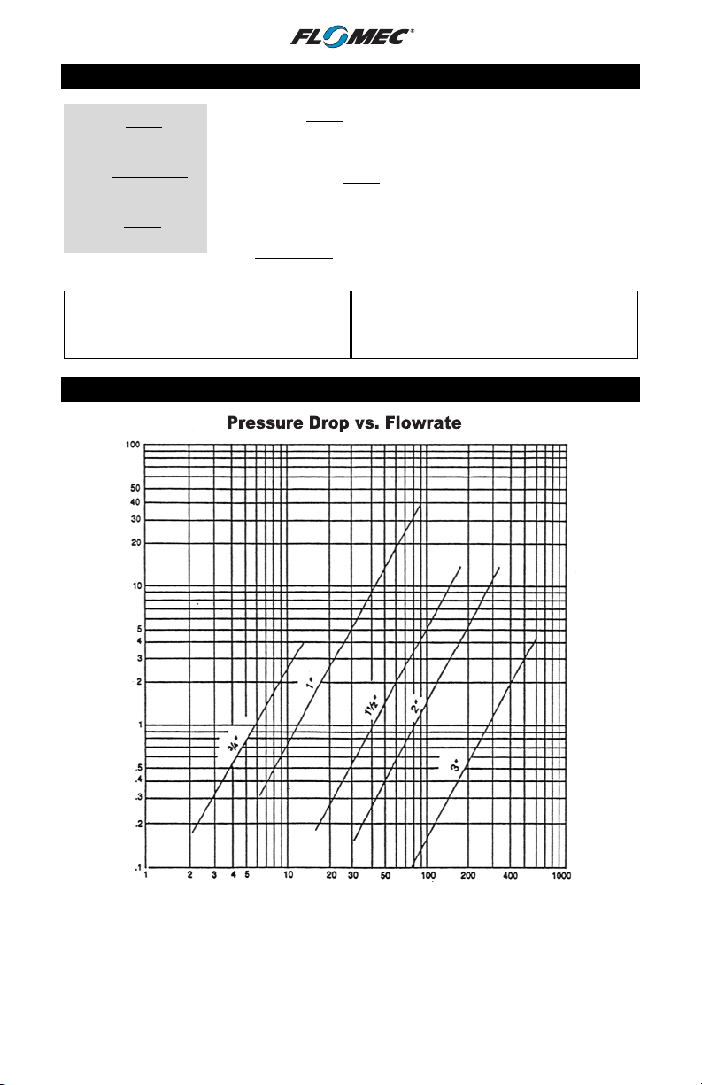
PRESSURE DROP vs FLOWRATE
Pressure Drop PSI
Flowrate Gallons Per Minute
For estimating pressure drops on liquids other than water, use the following formulas:
P = [ VISC (CPS) ] 1/4 x [ S.G. ] ¾ [ PH O ]
Where: CPS = Absolute Viscosity in Centipoise
SG = Specific Gravity
PH O = Pressure Drop at the Operating Flowrate from the Chart
17
Page 18

SERVICE
For warranty consideration, contact your local distributor. If you need further
assistance, contact the GPI Customer Service Department at:
1-888-996-3837
You will need to:
•
Provide the model number of your turbine.
•
The serial number of your turbine.
•
Specific information about part numbers and descriptions.
For warranty work always be prepared with your original sales slip or other
evidence of purchase date.
RETURNING PARTS
Please contact the factory before returning any parts. It may be possible to
diagnose the trouble and identify needed parts in a telephone call. GPI can also
inform you of any special handling requirements you will need to follow covering
the transportation and handling of equipment that has been used to transfer
hazardous or flammable liquids.
CAUTION: Do not return turbines without specific authority from the GPI Customer
Service Department. Due to strict regulations governing transportation, handling,
and disposal of hazardous or flammable liquids, GPI will not accept turbines for
rework unless they are completely free of liquid residue.
CAUTION: Turbines not flushed before shipment can be refused and returned to
the sender.
18
Page 19

NOTES
________________________________________________________________
________________________________________________________________
________________________________________________________________
________________________________________________________________
________________________________________________________________
________________________________________________________________
________________________________________________________________
________________________________________________________________
________________________________________________________________
________________________________________________________________
________________________________________________________________
________________________________________________________________
________________________________________________________________
________________________________________________________________
________________________________________________________________
________________________________________________________________
________________________________________________________________
________________________________________________________________
________________________________________________________________
________________________________________________________________
________________________________________________________________
________________________________________________________________
________________________________________________________________
________________________________________________________________
________________________________________________________________
________________________________________________________________
________________________________________________________________
19
Page 20

FLOMEC® TWO-YEAR LIMITED WARRANTY
Great Plains Industries, Inc. 5252 E. 36th Street North, Wichita, KS USA 67220-3205, hereby
provides a limited warranty against defects in material and workmanship on all products
manufactured by Great Plains Industries, Inc. This product includes a 2-year warranty.
Manufacturer’s sole obligation under the foregoing warranties will be limited to either, at
Manufacturer’s option, replacing or repairing defective Goods (subject to limitations
hereinafter provided) or refunding the purchase price for such Goods theretofore paid by the
Buyer, and Buyer’s exclusive remedy for breach of any such warranties will be enforcement
of such obligations of Manufacturer. The warranty shall extend to the purchaser of this
product and to any person to whom such product is transferred during the warranty period.
The warranty period shall begin on the date of manufacture or on the date of purchase with
an original sales receipt. This warranty shall not apply if:
A. the product has been altered or modified outside the warrantor’s duly appointed
representative;
B. the product has been subjected to neglect, misuse, abuse or damage or has been
installed or operated other than in accordance with the manufacturer’s operating
instructions.
To make a claim against this warranty, or for technical assistance or repair, contact your
FLOMEC distributor or contact FLOMEC at one of the locations below.
In North or South America contact
Great Plains Industries, Inc.
5252 East 36th St. North
Wichita, KS 67220-3205
USA
888-996-3837
www.flomecmeters.com
(North America)
The company will step you through a product troubleshooting process to determine
appropriate corrective actions.
Outside North or South America contact
GPI Australia
(Trimec Industries Pty. Ltd.)
12/7-11 Parraweena Road
Caringbah NSW 2229
Australia
+61 02 9540 4433
www.flomec.com.au
GREAT PLAINS INDUSTRIES, INC., EXCLUDES LIABILITY UNDER THIS WARRANTY
FOR DIRECT, INDIRECT, INCIDENTAL AND CONSEQUENTIAL DAMAGES INCURRED IN
THE USE OR LOSS OF USE OF THE PRODUCT WARRANTED HEREUNDER.
The company herewith expressly disclaims any warranty of merchantability or fitness for any
particular purpose other than for which it was designed.
This warranty gives you specific rights and you may also have other rights which vary from
U.S. state to U.S. state.
NOTE: In compliance with MAGNUSON MOSS CONSUMER WARRANTY ACT – Part 702
(governs the resale availability of the warranty terms).
© 2021 Great Plains Industries, Inc., All Rights Reserved.
Great Plains Industries, Inc. / 888-996-3837 / flomecmeters.com
11/2021 921977-02 Rev. G
20
 Loading...