

Page 1
Bulletin E-81-GS
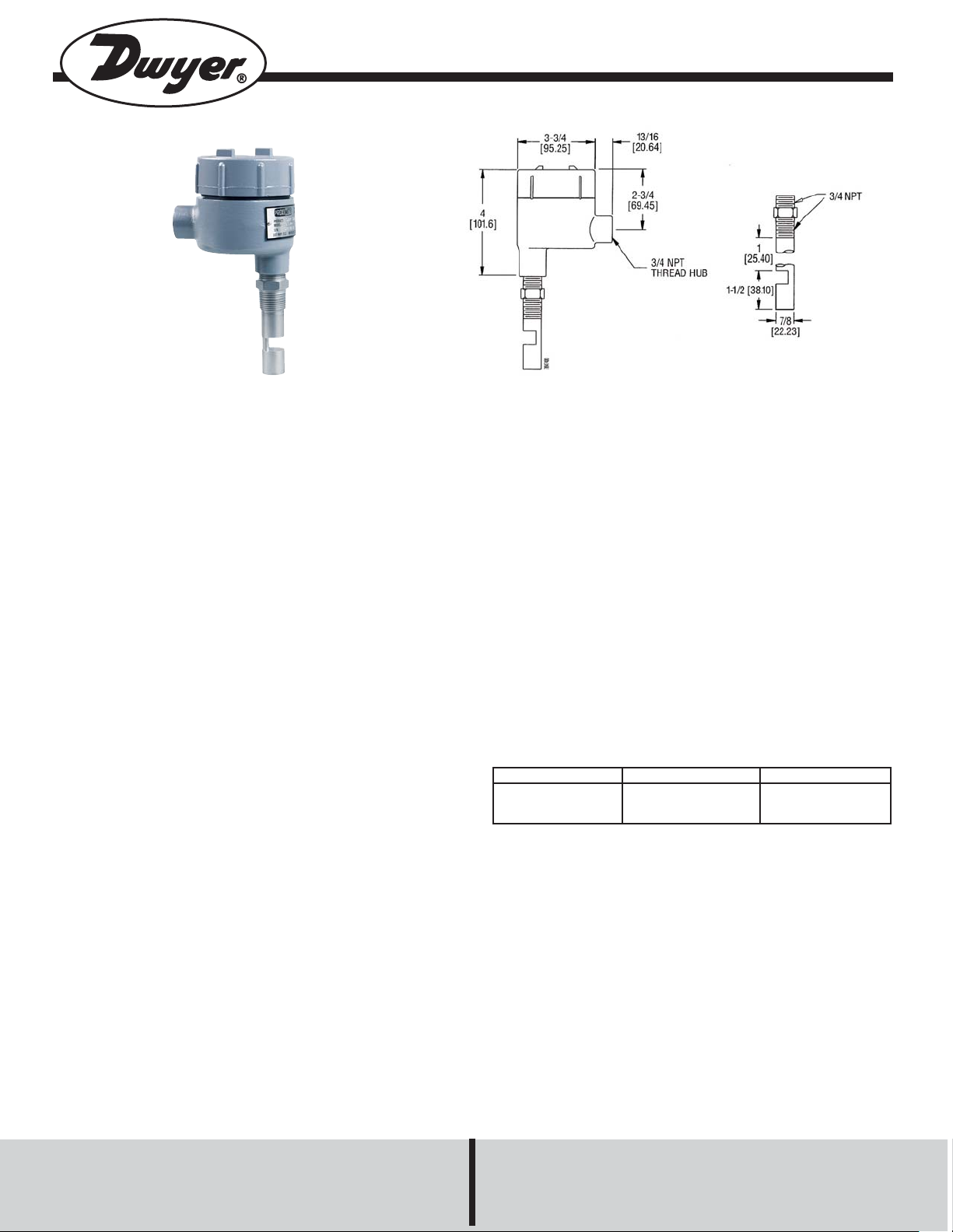
Series GS Gap Switch
Specifications - Installation and Operating Instructions
GENERAL
The Series GS Gap Switch can be used to monitor and
control levels of water, chemicals, lubricants, acids, creams,
lotions, beverages, or paints in vessels, storage bins, tanks,
and pumps. The Gap Switch operates using ultrasonic
sound wave propagation. Ultrasonic sound waves are
greatly attenuated when transmitted through air.
Conversely, when a liquid is present, the transmission of the
sound waves is greatly enhanced. The unit generates electrical signals that are converted to bursts of ultrasonic energy at the sensor. The ultrasonic bursts are transmitted
across the liquid sensing gap of the sensor. Upon receipt of
a valid signal at the receiver, the solid state electronics generate a “data enable” condition indicating that a liquid is
present. The signal energizes a relay and provides an output condition.
INSTALLATION
The Series GS with integral electronics can be mounted in
any position or orientation desired. Make sure all wiring,
conduit and electrical fittings conform to local electrical
coded.
PHYSICAL DATA
Repeatability: 2 mm (0.078˝) typical.
Delay [On]: 0.5 seconds.
Wet/Dry Ratio: 1000:1.
Supply Voltage: 115 VAC, 50/60 Hz standard, (230 VAC
available).
Output: 10A DPDT relay.
Immersion Depth: 1˝ (25.4 mm).
Sensor Material: 316 stainless steel.
Maximum Pressure: 1000 psig.
Temperature Range: Sensor: -40 to 200°F (-40 to
93°C), Electronics: -20 to 170°F (-4 to 77°C).
Housing: Epoxy-coated cast aluminum, NEMA 4 & 7
explosion proof; Class I, Groups C,D; Class II, Groups
E,F,G; Class III, Div. 1 & 2.
Conduit Opening: 3/4˝ NPT(M)
Weight: 1 lb (453 g).
Model Number
GS10001
GS20001
Immersion Depth
1˝ (25.4 mm)
1˝ (25.4 mm)
Supply Voltage
115 VAC
230 VAC
Preliminary Operational Check
Before installing the unit, a simple operation check should
be performed as follows:
Warning: Never open the housing cover in a hazardous
environment or connect the power leads without first disconnecting the electrical power at its source.
1) Fill a container with a liquid.
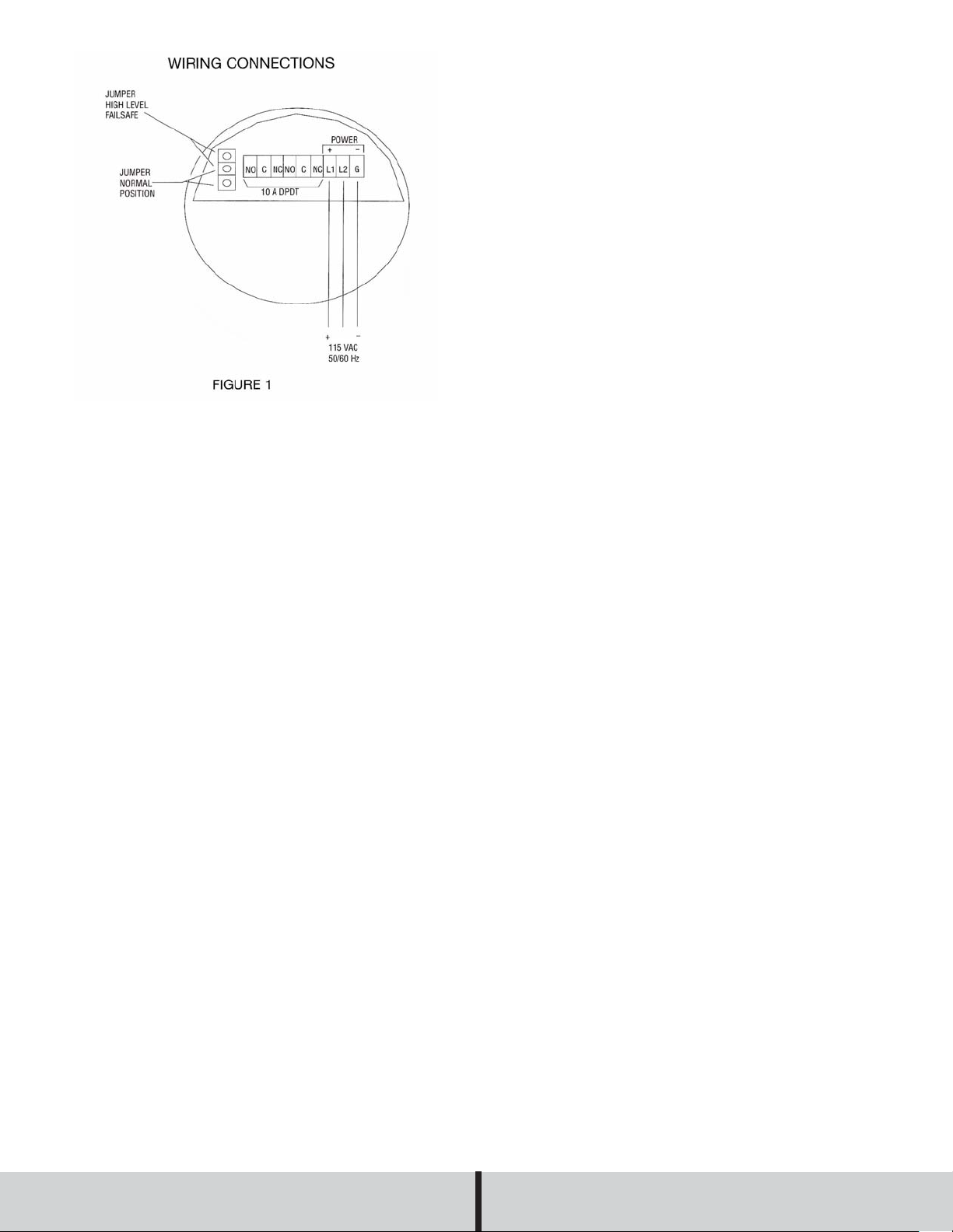
2) Open the housing cover and connect the power to the
control unit. See Figure 1.
3) Apply power from the source.
4) Place the sensor in the liquid. The relay should energize.
5) Remove the sensor from the liquid. The relay will de-energize indicating the system is functioning properly.
6) Disconnect the power to the unit.
7) Proceed to final installation if results were positive.
DWYER INSTRUMENTS, INC.
Phone: 219/879-8000 www.dwyer-inst.com
Page 2
NOTE: All wiring and connections should conform to local
codes. In a hazardous location, a conduit seal should be
installed within 18 inches of the unit housing. Use a drain
seal in a vertical conduit run to prevent condensation from
entering the electronics.
5. Replace the encapsulated electronics. Make sure the
wires are dressed carefully to prevent pinching between
the cover and housing.
6. Replace housing cover.
MAINTENANCE
The electronics are constructed with solid state components and are epoxy encapsulated. Periodically check and
clean the sensor when used with liquids which cause a
coating build-up on the sensor. No other routine maintenance is required on the Series GS Gap Switch.
Final Installation
1. Drill a suitable hole in the vessel or pipe wall and tap for
3/4˝ NPT. In a thin-walled vessel or when the material is
not suitable for threading, weld or braze a brushing to
accept the sensor.
2. Screw the sensor into the threaded section on the vessel, be sure there is a good seal. Use a pipe compound
or sealing tape compatible with the materials and avoid
excessive tightening.
3. Run the power and other wiring to the electronics in the
sensor head, observing applicable wiring codes and procedures.
CAUTION: Never remove the unit from a vessel with power
and/or output cables connected to the electronics. Cable
damage may result.
4. To complete wiring, remove the housing cover and the
encapsulated electronics. See Figure 1.
For Cleaning
If the pipe or vessel in which the unit is mounted is to be
steam cleaned with abrasive detergents, remove the entire
unit before cleaning by:
1) Disconnecting the power at the source.
2) Opening the housing cover.
3) Removing the power and control wiring cables.
4) Unthreading the sensor.
To reinstall, follow the installation procedures.
If the unit should need repairs, please contact Dwyer
Instruments, Inc. before returning unit to review information
relative to your application and obtain a return authorization
number. When returning a product to the factory, carefully
package and ship freight prepaid. Be sure to include a complete description of the application and problem and identify any hazardous material used with the product.
©Copyright 1998 Dwyer Instruments, Inc. Printed in U.S.A. 8/98 FR R1-443064-00
DWYER INSTRUMENTS, INC.
Phone: 219/879-8000 www.dwyer-inst.com
 Loading...