

Page 1
Advanced Instruments, Inc.
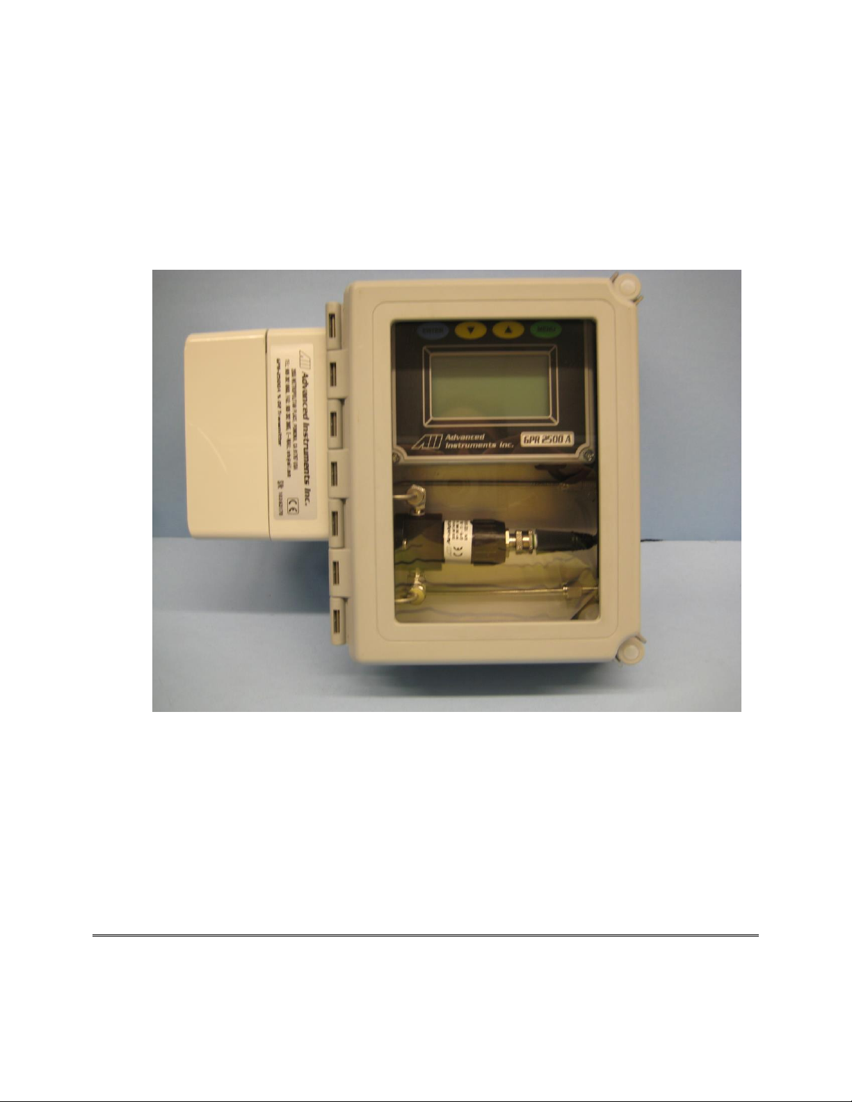
GPR-2500A
% Oxygen Analyzer
Owner’s Manual
Revised June 2014
Revised July 2018
2855 Metropolitan Place, Pomona, CA 91767 USA Tel: 909-392-6900, Fax: 909-392-3665, e-mail: [email protected], www.aii2.com
Page 2

Advanced Instruments, Inc.
2
Table of Contents
Introduction
1
Quality Control Certification
2
Safety
3
Features & Specifications
4
Operation
5
Maintenance
6
Spare Parts
7
Troubleshooting
8
Warranty
9
Material Safety Data Sheets
10
Drawings
A/R
Page 3

Advanced Instruments, Inc.
3
1. Introduction
Your new oxygen transmitter incorporated an advanced electrochemical sensor specific to oxygen along
with state-of-the-art digital electronics designed to give you years of reliable precise oxygen
measurements in a variety of industrial oxygen applications.
To obtain maximum performance from your new oxygen transmitter, please read and follow the
guidelines provided in this Owner’s Manual.
Every effort has been made to select the most reliable state of the art materials and components, to
design the transmitter for superior performance and minimal cost of ownership. This transmitter was
tested thoroughly by the manufacturer prior to shipment for best performance.
However, all electronic devices do require service from time to time. The warranty included herein plus a
staff of trained professional technicians to quickly service your transmitter is your assurance that we
stand behind every transmitter sold.
The serial number of this transmitter may be found on the inside the transmitter. You should note the
serial number in the space provided below and retain this Owner’s Manual as a permanent record of your
purchase, for future reference and for warranty considerations.
Serial Number: _______________________
Advanced Instruments Inc. appreciates your business and pledges to make every effort to maintain the
highest possible quality standards with respect to product design, manufacturing and service.
Page 4
Advanced Instruments, Inc.
4
2. Quality Control Certification
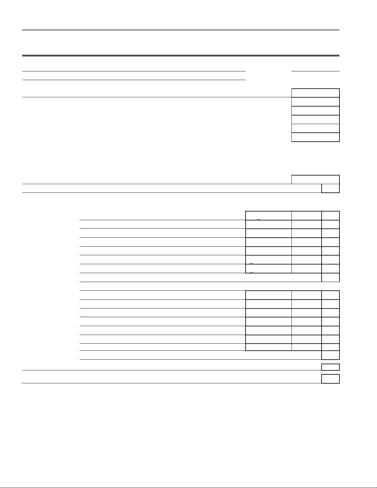
Quality Control & Calibration Certification
Customer:
Date:
Order No.:
Model:
GPR-2500 A Oxygen Analyzer
S/N:
Configuration:
( )
A-1161-AIS-2-I Rev C4 PCB Assembly, Main 4-20 mA Signal Output
Batch:
( )
A-1161-AIS-2-V Rev C4 PCB Assembly, Main 1-5 V Signal Output
( )
A-1166-AIS-I-2 Rev J2 PCB Assembly, Interconnection (12-28 VDC), 4-20 mA
Batch:
( )
A-1166-AIS-V-2 Rev J2 PCB Assembly, Interconnection (12-28 VDC), 1-5 VDC
Batch:
Ranges: 0-1%, 0-5%, 0-10%, 0-25%
Software Ver:
Barometric pressure and temperature compensation
A-2221 Flow Housing, 1/8" SS tubing, connections
Wall mount fiberglass NEMA 4X enclosure, 1/8" SS tube connections
Sensor:
( )
GPR-11-32-4 Oxygen Sensor
( )
XLT-11-24-4 Oxygen Sensor
S/N:
Accessories:
Owner’s Manual
Expected
Observed
Value
Value
Pass
Test & Verify:
Default zero
.00 + .05 low range
Default span in air @ 40 µA
19.0% to 23.0%
Span calibration upper limit in air @ 55 uA
20.5% to 21.3%
Span calibration lower limit in air @ 35 uA
20.5% to 21.3%
Reading after air (20.9%) calibration
20.5% to 21.3%
Baseline drift over 1 hour period (+5% FS) on 1% range
+ 0.05% of reading
Noise level (+1% FS) on 1% range
+ 0.01% of reading
Analog signal output 4-20 mA full scale
Alarm 1
Alarm 2
SETPOINT - Set alarm thresholds
MODE - Verify activation mode HIGH / LOW relative to setpoint
ENABLED - Verify alarms do not activate and OFF replaces SETPOINT
DELAY - Verify setpoint must be exceeded before activation
LATCHING - Verify alarms latching and non-latching modes
SILENCE/BYPASS - Verify main menu option de-activates alarm
FAIL SAFE - Verify relay opens (de-energizes) during alarm condition
Overall inspection for physical defects
Options:
NA
Other:
NA
Page 5
Advanced Instruments, Inc.
5
3. Safety
General
This section summarizes the essential precautions applicable to the GPR-2500A Oxygen Transmitter.
Additional precautions specific to individual transmitter are contained in the following sections of this
manual. To operate the transmitter safely and obtain maximum performance follow the basic guidelines
outlined in this Owner’s Manual.
Caution: This symbol is used throughout the Owner’s Manual to Caution and alert the user
to recommended safety and/or operating guidelines.
Danger: This symbol is used throughout the Owner’s Manual to identify sources of
immediate danger such as the presence of hazardous voltages.
Read Instructions: Before operating the transmitter read the instructions.
Retain Instructions: The safety precautions and operating instructions found in the Owner’s Manual
should be retained for future reference.
Heed Warnings: Follow all warnings on the transmitter, accessories (if any) and in this Owner’s Manual.
Follow Instructions: Observe all precautions and operating instructions. Failure to do so may result in
personal injury or damage to the transmitter.
Pressure and Flow
Inlet Pressure: GPR-2500A Oxygen Transmitters are designed for flowing samples, equipped with 1/8”
bulkhead tube fitting connections on the side of the unit (unless otherwise indicated, either fitting can
serve as inlet or vent) and are intended to operate at positive sample pressure regulated between 5-30
psig.
Caution: If equipped with a H2S scrubber as part of an optional sample conditioning system,
inlet pressure must not exceed 30 psig.
Outlet Pressure: The sample gas must be vented to atmosphere or vent pipe with atmospheric
pressure.
Installation
Oxygen Sensor: DO NOT open the sensor. The sensor contains a corrosive liquid electrolyte that could
be harmful if touched or ingested, refer to the Material Safety Data Sheet contained in the Owner’s
Manual appendix. Avoid contact with any liquid or crystal type powder in or around the sensor or sensor
housing, as either could be a form of electrolyte. Leaking sensors should be disposed of in accordance
with local regulations.
Mounting of the Transmitter: The transmitter is approved for indoor or outdoor use. Mount the
transmitter on a flat surface.
Power Requirement: Supply power to the transmitter only as rated by the specification or markings on
the transmitter enclosure. The wiring that connects the transmitter to the power source should be
installed in accordance with recognized electrical standards and so they are not pinched particularly near
the power source and the point where they attach to the transmitter. Never yank wiring to remove it
from an outlet or from the transmitter.
Operating Temperature: The maximum operating temperature is between 00C to 45º C.
Heat: Situate and store the transmitter away from sources of heat.
Liquid and Object Entry: The transmitter should not be immersed in any liquid. Care should be taken
so that liquids are not spilled into and objects do not fall into the inside of the transmitter.
Page 6

Advanced Instruments, Inc.
6
Handling: Do not use force when using the switches or terminal blocks. Before moving your transmitter,
be sure to disconnect the wiring/power cord and any cables connected to the output terminals located on
the transmitter.
Maintenance
Serviceability: Except for replacing the oxygen sensor, there are no parts inside the transmitter for the
operator to service.
Only trained personnel with the authorization of their supervisor should conduct maintenance.
Oxygen Sensor: DO NOT open the sensor. The sensor contains a corrosive liquid electrolyte that could
be harmful if touched or ingested, refer to the Material Safety Data Sheet contained in the Owner’s
Manual appendix. Avoid contact with any liquid or crystal type powder in or around the sensor or sensor
housing, as either could be a form of electrolyte. Leaking sensors should be disposed of in accordance
with local regulations.
Troubleshooting: Consult the guidelines in Section 8 for advice on the common operating errors before
concluding that your transmitter is faulty.
Do not attempt to service the transmitter beyond those means described in this Owner’s Manual. Do not
attempt to make repairs by yourself as this will void the warranty as per Section 10 and may result in
electrical shock, injury or damage. All other servicing should be referred to qualified service personnel.
Cleaning: The transmitter should be cleaned only as recommended by the manufacturer. Wipe off dust
and dirt from the outside of the unit with a soft damp cloth then dry immediately. Do not use solvents or
chemicals.
Nonuse Periods: If the transmitter is equipped with a range switch advance the switch to the OFF
position and disconnect the power when the transmitter is left unused for a long period of time.
Page 7
Advanced Instruments, Inc.
7
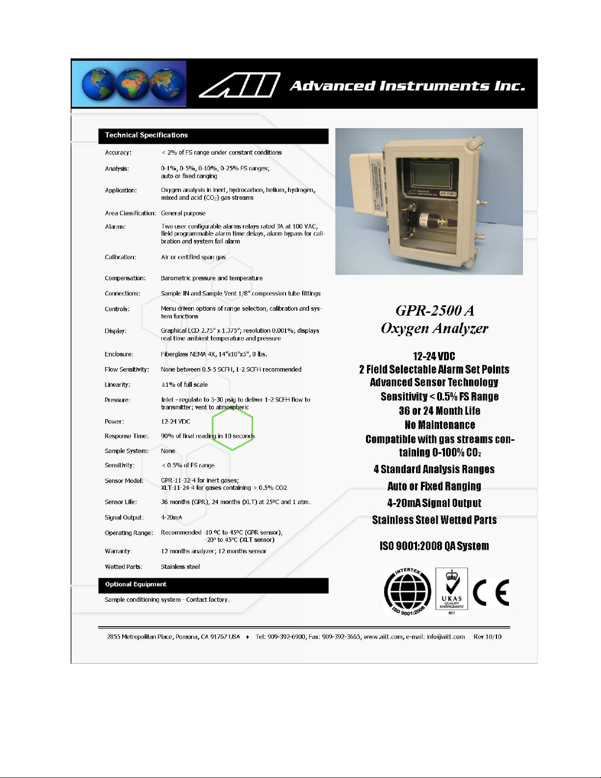
4. Features and Specification
Page 8

Advanced Instruments, Inc.
8
5. Operation
Principle of Operation
The GPR-2500A oxygen transmitter incorporates a variety of advanced galvanic fuel cell type sensors.
The transmitter is a compact efficient package configured with the oxygen sensor and separate circuit
boards for signal processing and terminals for incoming power, power supply, signal output and alarm
relay contacts housed in a general purpose NEMA 4X rated enclosure.
Advanced Galvanic Sensor Technology
The sensors function on the same principle and are specific for oxygen. They measure the partial
pressure of oxygen from low ppm to 100% levels in inert gases, gaseous hydrocarbons, helium,
hydrogen, mixed gases, acid gas streams and ambient air. Oxygen, the fuel for this electrochemical
transducer, diffusing into the sensor reacts chemically at the sensing electrode to produce an electrical
current output proportional to the oxygen concentration in the gas phase. The sensor’s signal output is
linear over all ranges and remains virtually constant over its useful life. The sensor requires no
maintenance and is easily and safely replaced at the end of its useful life.
Electronics
The signal generated by the sensor is processed by state of the art low power micro-processor based
digital circuitry. The first stage amplifies the signal. The second stage eliminates the low frequency noise.
The third stage employs a high frequency filter and compensates for signal output variations caused by
ambient temperature changes. The result is a very stable signal. Sample oxygen is analyzed very
accurately. Response time of 90% of full scale is less than 10 seconds (actual experience may vary due
to the integrity of sample line connections, dead volume and flow rate selected) on all ranges under
ambient monitoring conditions. Sensitivity is typically 0.5% of full scale low range. Oxygen readings may
be recorded by an external device via the 0-1V signal output jack.
The circuit for the 4-20mA signal output and two adjustable alarms is powered by a DC/DC transformer
that requires a 12-24VDC power source and separate wiring for the signal outputs.
Caution: A loop power source is not sufficient to power this transmitter. Further, the 4-20mA signal
output does not require any external power (applying power to 4-20 mA terminal will permanently
damage the transmitter and void transmitter warranty).
Sample System
The GPR-2500A is supplied without a sample conditioning system thereby giving users the option of
adding their own or purchasing a factory designed sample conditioning system. Whatever the choice, the
sample must be properly presented to the sensor to ensure an accurate measurement. Users interested
in adding their own sample conditioning system should consult the factory. Advanced Instruments Inc.
offers a full line of sample handling, conditioning and expertise to meet your application requirements.
Contact us at 909-392-6900 or e-mail us at [email protected]
Pressure and Flow Consideration
All electrochemical oxygen sensors respond to partial pressure changes in oxygen. The inlet pressure
must always be higher than the pressure at the outlet vent which is normally at atmospheric pressure.
Flow-Through Configuration
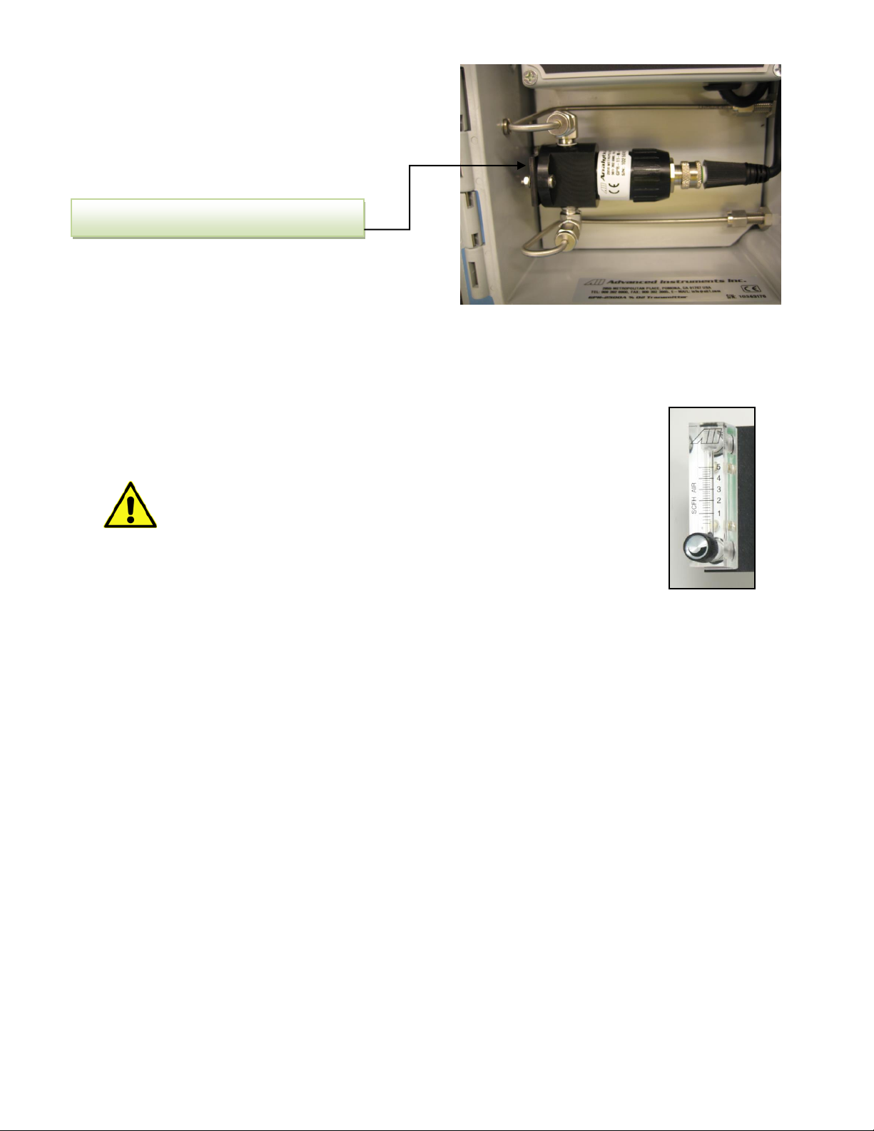
The sensor is exposed to sample gas that must flow or be drawn through the sensor housing inside the
transmitter. The GPR-2500A internal sample system includes 1/8” compression tube sample inlet and
vent fittings, a Delrin or optional stainless steel sensor housing.
Page 9
Advanced Instruments, Inc.
9
Flow rates of 1-5 SCFH cause no appreciable change in the oxygen reading. However, flow rates above 5
SCFH generate backpressure and erroneous oxygen readings because the diameter of the integral tubing
cannot evacuate the sample gas at the higher flow rate. The direction the sample gas flows is not
important, thus either of the two tube fitting connectors can serve as the inlet or vent.
A flow indicator with an integral metering valve upstream of the sensor is
recommended as a means of controlling the flow rate of the sample gas. A flow rate of
1-2 SCFH or 0.4-1 liter per minute is recommended for optimum performance.
Caution: Do not place your finger over the vent (it pressurizes the sensor)
to test the flow indicator when gas is flowing to the sensor. Removing your
finger (the restriction) generates a vacuum on the sensor and may damage
the sensor (voiding the sensor warranty).
Application Pressure - Positive:
A flow indicator with integral metering valve positioned upstream of the sensor is recommended for
controlling the sample flow rate between 1-5 SCFH. If necessary, a pressure regulator (pressure regulator
with a metallic diaphragm is recommended for optimum accuracy, the use of more permeable materials
may result in erroneous readings) upstream of the flow control valve should be used to regulate the inlet
pressure between 5-30 psig.
Caution: If equipped with a H2S scrubber as part of an optional sample conditioning system, inlet
pressure must not exceed 30 psig.
Application Pressure - Atmospheric or Slightly Negative:
For accurate oxygen measurements, an optional external sampling pump should be positioned upstream
of the sensor to draw the sample from the process and push it through the sensor housing and out to
atmosphere. A flow meter is not necessary if the discharge of the sampling pump approximates the
recommended 1-2 SCFH flow rate.
If pump loading is a consideration, a second throttle valve on the pump’s inlet side may be necessary to
provide a bypass path so the sample flow rate is within the above parameters.
To avoid erroneous oxygen readings and damage to the sensor:
• Do not place your finger over the vent (it pressurizes the sensor) to test the flow indicator when
gas is flowing to the sensor. Removing your finger (the restriction) generates a vacuum on the
sensor and may damage the sensor (voiding the sensor warranty).
• Assure there are no restrictions in the sample or vent lines
• Avoid drawing a vacuum that exceeds 14” of water column pressure – unless done gradually
Delrin Senor Housing with sensor installed.
Page 10

Advanced Instruments, Inc.
10
• Avoid excessive flow rates above 5 SCFH which generate backpressure on the sensor.
• Avoid sudden releases of backpressure that can severely damage the sensor.
• Avoid the collection of particulates, liquids or condensation collect on the sensor that could block
the diffusion of oxygen into the sensor.
• If the transmitter is equipped with an optional integral sampling pump (positioned downstream of
the sensor) and a flow control metering valve (positioned upstream of the sensor), completely
open the flow control metering valve to avoid drawing a vacuum on the sensor and placing an
undue burden on the pump.
Page 11
Advanced Instruments, Inc.
11
Choices of Calibration & Accuracy
Single Point Calibration: As previously described the galvanic oxygen sensor generates an electrical
current sensor exhibiting an absolute zero, e.g. the sensor does not generate a current output in the
absence of oxygen. Given these linearity and absolute zero properties, single point calibration is possible.
Pressure: Because sensors are sensitive to the partial pressure of oxygen in the sample gas their
output is a function of the number of molecules of oxygen 'per unit volume'. Readouts in percent are
permissible only when the total pressure of the sample gas being analyzed remains constant. The
pressure of the sample gas and that of the calibration gas(es) must be the same (reality < 1-2 psi).
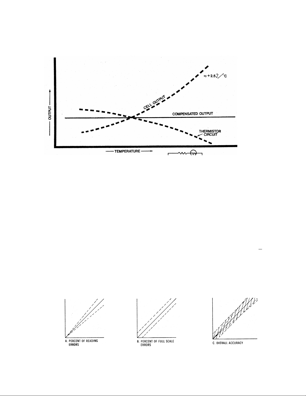
Temperature: The rate oxygen molecules diffuse into the sensor is controlled by a Teflon membrane
otherwise known as an 'oxygen diffusion limiting barrier' and all diffusion processes are temperature
sensitive, the fact the sensor's electrical output will vary with temperature is normal. This variation is
relatively constant 2.5% per ºC. A temperature compensation circuit employing a thermistor offsets this
effect with an accuracy of +5% (over the recommended operating temperature range) or better and
generates an output signal that is relatively independent of temperature. Note: There is no error if the
calibration and sampling are performed at the same temperature or if the measurement is made
immediately after calibration. Lastly, small temperature variations of 10-15º produce < +1% error.
Accuracy: In light of the above parameters, the overall accuracy of an transmitter is affected by two
types of errors: 1) those producing 'percent of reading errors', illustrated by Graph A below, such as +5%
temperature compensation circuit, tolerances of range resistors and the 'play' in the potentiometer used
to make span adjustments and 2) those producing 'percent of full scale errors', illustrated by Graph B,
such as +1-2% linearity errors in readout devices, which are really minimal due to today's technology
and the fact that other errors are 'spanned out' during calibration.
Graph C illustrates these 'worse case' specifications that are typically used to develop an transmitter's
overall accuracy statement of +2% of full scale at constant temperature or +5% over the operating
temperature range. QC testing is typically <+0.5% prior to shipment.
Page 12

Advanced Instruments, Inc.
12
Example: As illustrated by Graph A any error, play in the multi-turn span pot or the temperature
compensation circuit, during a span adjustment at 20.9% (air) of full scale range would be multiplied by
a factor of 4.78 (100/20.9) if used for measurements of 95-100% oxygen concentrations. Conversely, an
error during a span adjustment at 100% of full scale range is reduced proportionately for measurements
of lower oxygen concentrations.
Recommendation: Calibrating with a span gas approximating 80% of the full scale range one or two
ranges higher than the full scale range of interest is recommended for 'optimum calibration accuracy'.
Always calibrate at the same temperature and pressure of the sample gas stream.
Page 13

Advanced Instruments, Inc.
13
Starting-up the Analyzer
The GPR-2500A Oxygen Transmitter has been tested, calibrated at the factory prior to shipment with the
sensor installed and is fully operational from the shipping container. Allow the transmitters to stabilize for
30 minutes and then recalibrate the device as instructed below.
Installation Considerations
The GPR-2500A consists of two circuit boards, sensor housing and sample 1/8” sample inlet and vent
connections housed in a NEMA 4X rated enclosure and is suitable for mounting on any vertical flat
surface.
For optimum accuracy zero and calibrate a transmitter after it has been allowed to stabilize, typically 2436 hours after installation. Assuming the initial zero is performed according to the procedure described
herein, the analyzer should not require zeroing again until the either the sensor is replaced or a change is
made to the sample system or gas lines. Following the initial zero and calibration, the analyzer should not
require span calibration again for up to 3 months under “normal” application conditions as described in
the published specifications.
Note: As described below, zeroing the transmitter is recommended only for measurements below 1%
and not practical for measurement ranges above 1%. The low end sensitivity (zero capability) has been
verified at the factory; however, no ZERO OFFSET adjustment has been made. A factory adjustment
would be meaningless because of the difference in sample systems and leakage factors between the
factory set-up and the actual application conditions.
Assemble the necessary hardware for mounting the transmitter and optional components - such as
coalescing or particulate filters and pumps, 1/8” metal or plastic tubing for interconnecting the
transmitter and optional components.
Temperature: The sample must be sufficiently cooled before it enters the transmitter and any optional
components. A coiled 10 foot length of ¼” stainless steel tubing is sufficient for cooling sample gases as
high as 1,800ºF to ambient.
Pressure & Flow as described above
Moisture & Particulates: Prevent water and/or particulates from entering the sample system. They can
clog the tubing and damage the optional components such as pumps, scrubbers or sensors. Installation
of a suitable coalescing or particulate filter is required to remove condensation, moisture and/or
particulates from the sample gas to prevent erroneous analysis readings and damage to the sensor or
optional components. Consult the factory for recommendations concerning the proper selection and
installation of components.
Contaminant Gases: A gas scrubber and flow indicator with integral metering valve are required
upstream of the transmitter to remove interfering gases such as oxides of sulfur and nitrogen or
hydrogen sulfide that can produce false readings and reduce the expected life of the sensor. Installation
of a suitable scrubber is required to remove the contaminant from the sample gas to prevent erroneous
analysis readings and damage to the sensor or optional components. Consult the factory for
recommendations concerning the proper selection and installation of components.
Gas Connections: Inlet and outlet vent gas lines require 1/8” diameter tubing preferably metal.
Power Connection: Locate a source of AC power to meet area classification and to plug in the charging
adapter.
Zero Calibration: Required only for very low percentage range measurements, less than 5% of full
scale at the most sensitive range of the analyzer.
Span Calibration: Users are responsible for certified span gas cylinder, regulator and flow control valve.
The analyzer must be calibrated with a certified span gas and regular intervals, typically every 30 days of
operation.
Page 14
Advanced Instruments, Inc.
14
Mounting the Analyzer
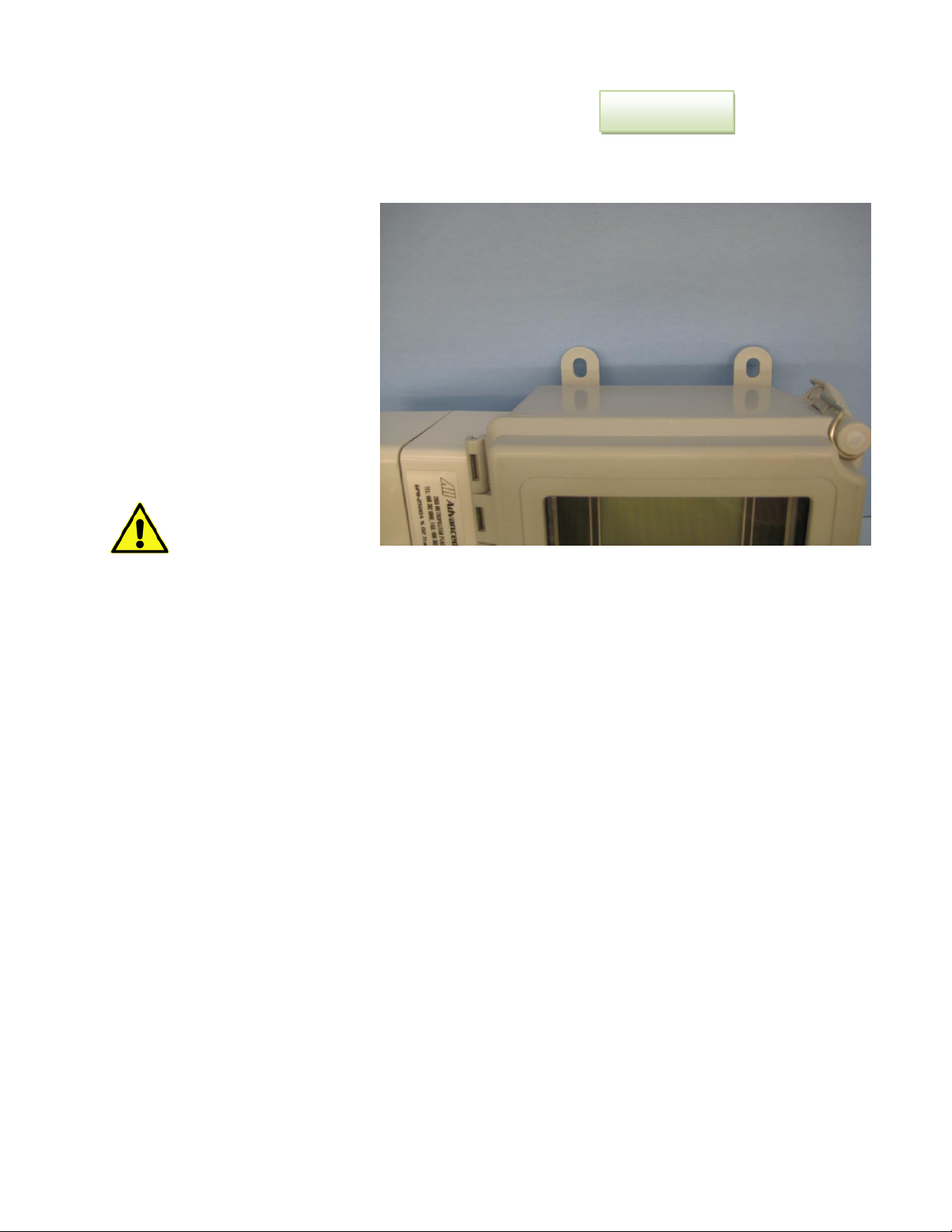
The GPR-2500A is housed in a Fiber Glass NEMA4X rated enclosure. This configuration is designed to be
mounted directly to any flat vertical surface, wall or bulkhead plate with four (4) of the appropriate size
screws. To facilitate servicing the interior of the transmitters, position it approximately 5 feet off ground
level.
• Loosen the four mounting
pads at the rear of the
enclosure.
• Select four appropriate
mounting screws (customer
supplied).
• Secure the enclosure to a
vertical surface
approximately 5 feet from
the floor or a level
accessible to service
personnel. This requires the
user to supply four (4)
additional proper size screws
and anchors.
Caution: Do not remove
or discard the gaskets
from either the enclosure
or junction box.
The transmitters design provides protection from RFI that is maintained by leaving specific mating areas
of the enclosure unpainted to maintain conductivity of the gasket, top and bottom sections of the smaller
enclosure housing the electronics. These unpainted areas are protected by gaskets and contribute to
maintaining the NEMA 4 rating as well as protection from RFI/EMI. Do not paint these areas.
Mounting Pads
Page 15
Advanced Instruments, Inc.
15
Gas Connections
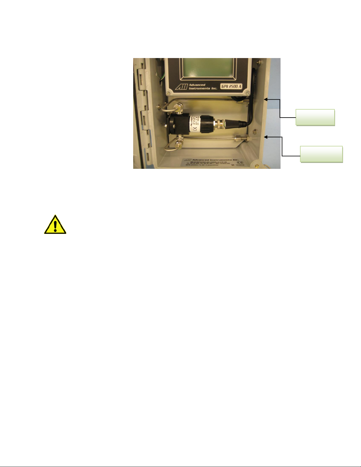
The GPR-2500A with its standard flow through configuration is designed for positive pressure samples
and requires connections for incoming sample and outgoing vent lines. The user is responsible for
calibration gases and other required components, see below.
Flow rates of 1-5 SCFH cause no appreciable change in the oxygen reading. However, flow rates above 5
SCFH generate backpressure and erroneous oxygen readings because the diameter of the integral tubing
cannot evacuate the sample gas at the higher flow rate. A flow indicator with an integral metering valve
upstream of the sensor is recommended as a means of controlling the flow rate of the sample gas. A flow
rate of 1-2 SCFH or 0.4-1 liter per minute is recommended for optimum performance.
Caution: Do not place your finger over the vent (it pressurizes the sensor) to test the flow
indicator when gas is flowing to the sensor. Removing your finger (the restriction) generates a
vacuum on the sensor and may damage the sensor (voiding the sensor warranty).
Procedure of Connecting Sample Gas:
• Designate one of the bulkhead tube fittings as the VENT and the other as SAMPLE.
• Regulate the sample/span gas pressure to 5-30 PSIG.
• Connect a 1/8” vent line to the compression fitting to be used for venting the sample.
• Connect a 1/8” ZERO, SPAN or SAMPLE line to the fitting designated SAMPLE.
• If equipped with optional fittings and/or sample system, connect the ZERO and or SPAN gas
lines.
• Allow gas to flow through the transmitters and set the flow rate to 1-2 SCFH.
Sample Vent
Sample In
Page 16

Advanced Instruments, Inc.
16
Installing the Oxygen Sensor
• Loosen the two (2) anchors securing the top lid of the enclosure.
• Remove the oxygen sensor from the bag.
• Screw the oxygen sensor into the sensor flow-through housing, finger tighten plus one half (1/4)
turn to ensure a good seal from the o-ring affixed to the sensor.
• Remove the shorting device (looped wire) from the receptacle located at the rear of the sensor.
• Assure the keyway registration of the female plug on the cable and male receptacle on the
sensor match up.
• Push the female plug on to the sensor mating connector
• Screw the knurled lock nut (attached to the cable) onto to the male connector (attached to the
sensor), tighten finger tight.
• Close the front cover of the transmitter and ensure that the gasket remains in place to maintain
CE approval and NEMA 4 rating.
• Secure the lid by the two (2) anchors
Proceed to calibration (see below for details).
Page 17
Advanced Instruments, Inc.
17
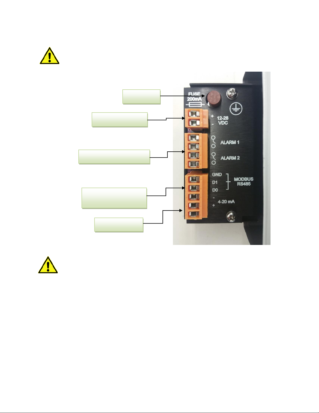
Electrical Connections
All electrical connections are located in a small junction box located on the side of the larger enclosure.
Power at the specified rating must be supplied via a two wire shielded cable. A safety fuse is also
mounted in the junction box.
Do not supply power beyond the rating. Failure to do so may permanently damage the
analyzer.
The integral 4-20mA converter is internally powered and does not require external power. DO
NOT supply any voltage to either of the two terminals of the 4-20mA output connector. Failure
to do so will permanently damage the 4-20mA converter.
Procedure
• Remove the front cover of the junction box located on left side of the transmitters by removing
the four (4) screws securing the cover and set them aside for reinstallation.
• Loosen the nut of the cable gland (customer provide and mounted at the bottom of the smaller
enclosure).
• Insert power and alarm and signal output wires through the cable gland. Strip ~ ¼ inch of the
wires. Insert the stripped end of wires to the appropriate terminals and secure them by
tightening the screws of the terminal block. Note: Use wires that comply with local regulatory
requirements.
• Thread the wires through the cable gland into the inside of the junction box.
• Ensure the positive and negative terminals of the power supply are connected to the appropriate
terminals.
Two user selectable Alarms
12-28 VDC Power In
Power Fuse
4-20 mA Signal
Modbus Communication
(Optional)
Page 18

Advanced Instruments, Inc.
18
• If using shielded cables, connect the shielding of the cable to the copper ground screw inside the
junction box.
• Replace the junction box cover ensuring the gaskets are in place and tighten the four (4) screws.
• Tighten the cable gland to maintain NEMA 4 rating.
Installation of Oxygen Sensor
The GPR-2500A Oxygen Transmitter is normally equipped with an integral oxygen sensor. It has been
tested and calibrated by the manufacturer prior to shipment and are fully operational from the shipping
container. However, when the application requires a remote sensor (external to the electronics enclosure)
or other special circumstances, the oxygen sensor will be packaged separately and must be installed prior
to operating the transmitter. If the sensor has not been installed at the factory, it will be necessary to
install the sensor in the field.
Note: All transmitters must be calibrated
once the installation has been completed
and periodically thereafter as described
below. Following the initial installation and
calibration, allow the transmitters to stabilize for 24 hours and perform a calibration again with a certified
span gas.
Caution: DO NOT open the oxygen sensor. The sensor contains a corrosive liquid electrolyte
that could be harmful if touched or ingested, refer to the Material Safety Data Sheet contained
in the Owner’s Manual appendix. Avoid contact with any liquid or crystal type powder in or
around the sensor or sensor housing, as either could be a form of electrolyte. Leaking sensors should be
disposed of in manner similar to that of a common battery in accordance with local regulations.
Delrin Housing with Oxygen
Sensor installed
Page 19

Advanced Instruments, Inc.
19
Span Calibration
Span Gas Preparation
One of the most accurate, reliable and inexpensive means of calibrating the GPR-2500A is to expose the
sensor to the 20.9% oxygen content found in ambient air. However, exposing the sensor to ambient air
with the GPR-2500A flow through configuration requires opening the enclosure and unscrewing the
sensor from its flow housing. However, many users opt to calibrate with a certified span gas which
requires additional components and time.
Caution: When using a certified span gas from a span gas cylinder, do not contaminate the span gas
cylinder when connecting the pressure regulator. When installing the pressure regulator, bleed the air
filled regulator to flush air from the regulator before securing it on the cylinder. When using a span gas,
always bleed the pressure regulator before opening the span gas to the analyzer (this requires a bypass
valve at the exit of the pressure regulator valve).
Note: Always use a certified span gas with an oxygen concentration, balance nitrogen, approximating
50-80% of the full scale range of interest or one range above the intended measuring range. You will
require the following components to deliver a span gas to the analyzer/transmitter.
Set the span gas pressure as close as possible to the sample gas pressure. This will assure a smooth shift
from sample to span or vise versa without the need to readjust the gas flow rate.
Page 20
Advanced Instruments, Inc.
20
Establishing Power to Electronics
Once the two power input wires of the shielded cable are properly connected to the terminals as
described above, connect the other end of the two wires to a suitable 12-28 VDC power source such as a
battery, PLC, DCS, etc.
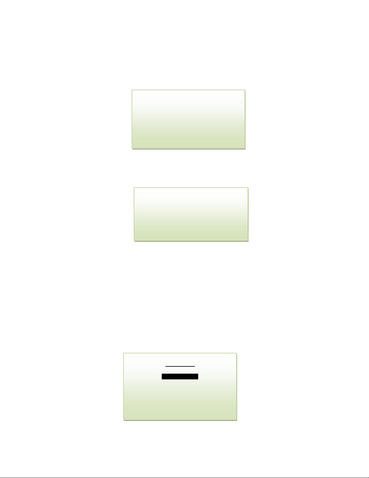
The digital display responds instantaneously. The analyzer performs several self-diagnostic system status
checks termed as “START-UP TEST” as illustrated below:
After self diagnostic tests, the transmitter turns itself into the sampling mode and displays the O2
contents the sensor is exposed to, the analysis range, the ambient temperature and pressure, and
high/low alarm set points.
Manu Navigation
The four (4) pushbuttons located on the front of the transmitter control the micro-processor functions:
Blue ENTER (select)
Yellow UP ARROW
Yellow DOWN ARROW
Green MENU (escape)
Main Menu
To access the MAIN MENU, press the MENU (ESC) key and the following screen will appear
START-UP TEST
ELECTRONICS – PASS
LOOP POWER – PASS
TEMP SENSOR – PASS
BARO SENSOR – PASS
S1010 1.35
20.9 %
AUTO SAMPLING
25 % RANGE
76 F 97 KPA
1L=2% 2H=22%
MAIN MENU
SELECT RANGE
CALIBRATION
VIEW HISTORY
SYSTEM OPTIONS
CONFIG ALARMS
BYPASS ALARMS
Page 21
Advanced Instruments, Inc.
21
Range Selection
The GPR-2500A transmitter is equipped with four (4) standard measuring ranges (see specification) and
provides users with a choice of sampling modes. By accessing the MAIN MENU, users may select either
the AUTO SAMPLING (ranging) or MANUAL SAMPLING (to lock on a single range) mode.
Note: For calibration purposes, use of the AUTO SAMPLE mode is recommended. However, the user can
also select the MANUAL SAMPLE mode for calibration but the span gas must not exceed the full scale of
the manual range selected.
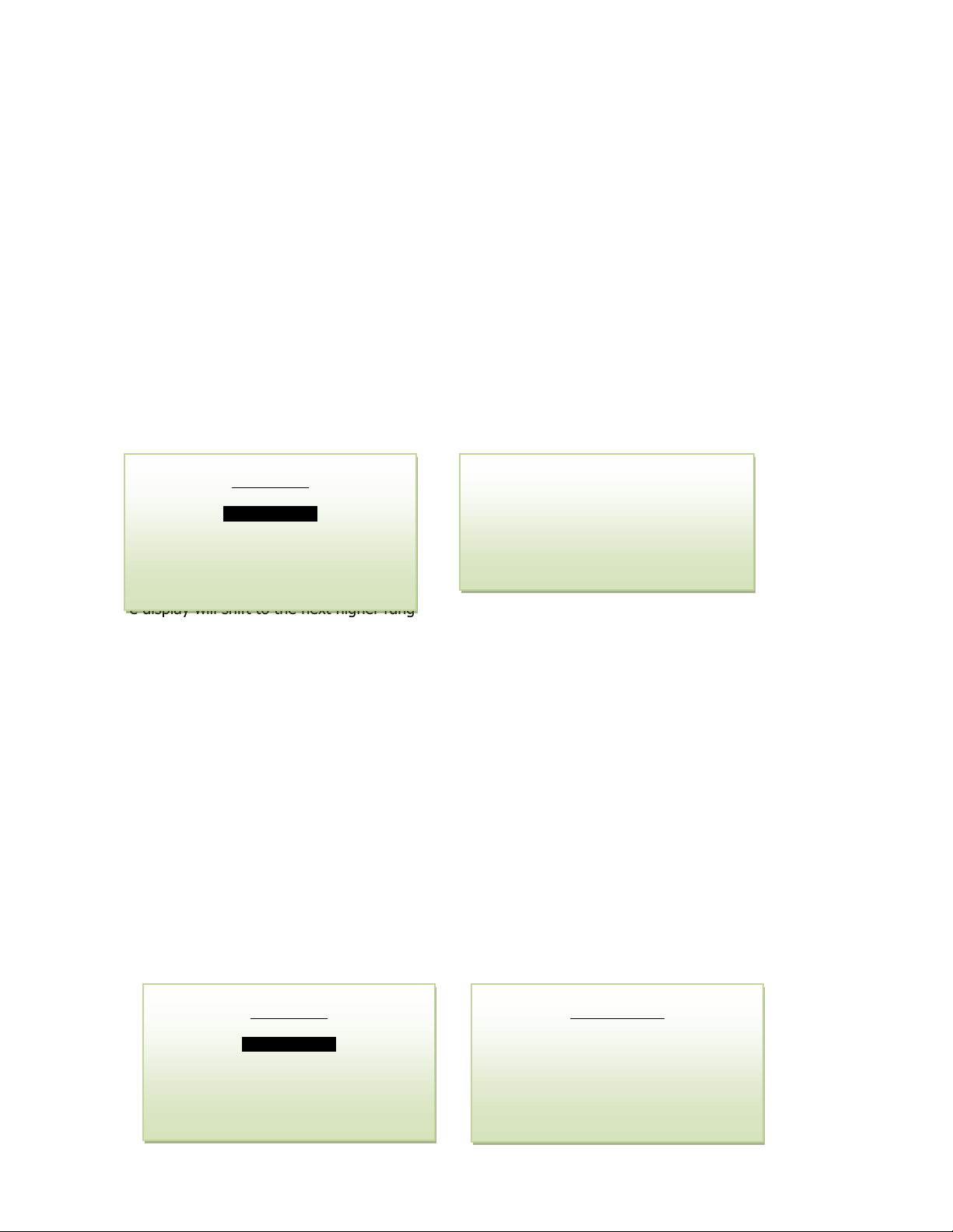
Auto Sampling
• Access the MAIN MENU by pressing the MENU key.
• Advance the reverse shade cursor using the ARROW keys to highlight SELECT RANGE.
• Press the ENTER key to select the highlighted menu option.
• Advance the reverse shade cursor using the ARROW keys to highlight AUTO.
• Press the ENTER key to select the highlighted menu option
• The display returns to the sampling mode:
The display will shift to the next higher range when the oxygen reading (actually the sensor’s signal
output) exceeds 99.9% of the upper limit of the current range. The display will shift to the next lower
range when the oxygen reading drops to 85% of the upper limit of the next lower range.
For example, if the transmitter is reading 1% on the 0-10% range and an upset occurs, the display will
shift to the 0-25% range when the oxygen reading exceeds 9.9%. Conversely, once the upset condition
is corrected, the display will shift back to the 0-10% range when the oxygen reading drops to 8.5%.
Manual Sampling
• Access the MAIN MENU by pressing the MENU key.
• Advance the reverse shade cursor using the ARROW keys to highlight SELECT RANGE.
• Press the ENTER key to select the highlighted menu option.
• Advance the reverse shade cursor using the ARROW keys to highlight the desired MANUAL
RANGE.
• Press the ENTER key to select the highlighted menu option.
The following displays appears:
MAIN MENU
SELECT RANGE
CALIBRATION
VIEW HISTORY
SYSTEM OPTIONS
CONFIG ALARMS
BYPASS ALARMS
20.9 %
AUTO SAMPLING
25 % RANGE
76 F 97 KPA
1L=2% 2H=22%
MAIN MENU
SELECT RANGE
CALIBRATION
VIEW HISTORY
SYSTEM OPTIONS
CONFIG ALARMS
BYPASS ALARMS
SELECT RANGE
AUTO
1 %
5 %
10 %
25 %
Page 22
Advanced Instruments, Inc.
22
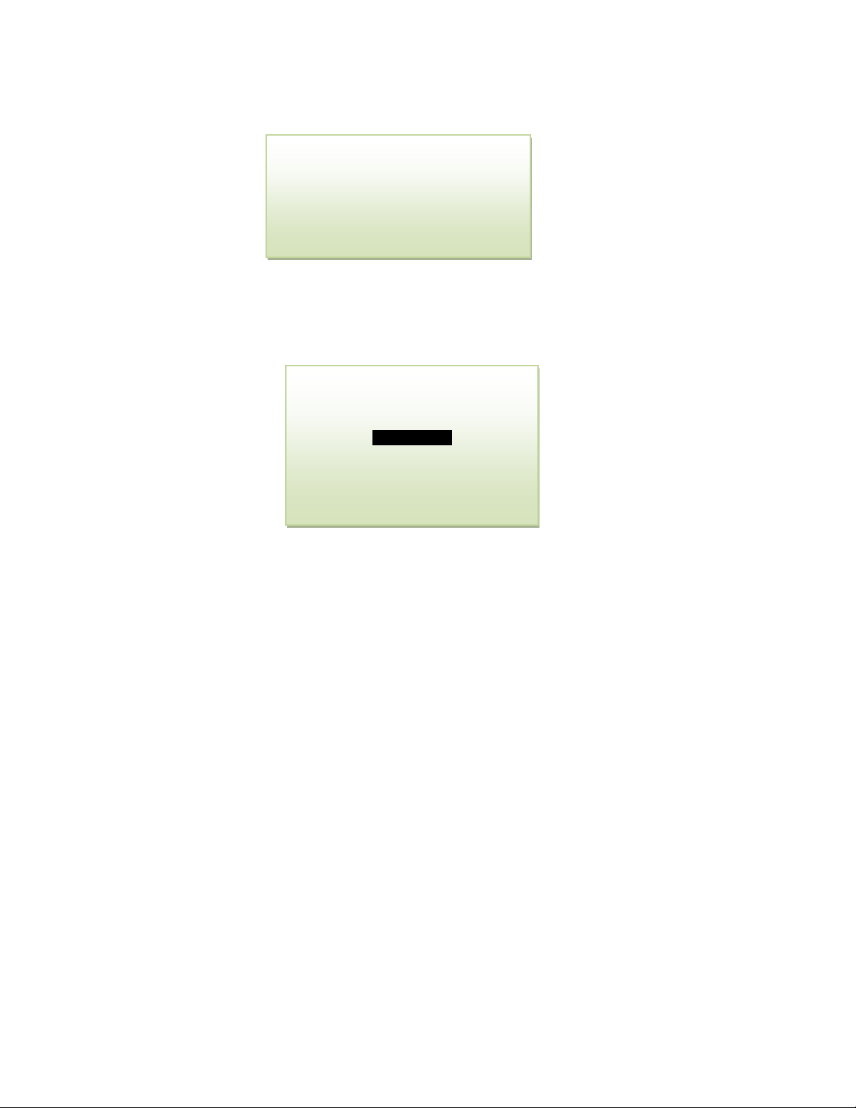
The following display appears with the range selected and oxygen concentration of the sample gas:
The display will not shift automatically. Instead, when the oxygen reading (actually the sensor’s signal
output) exceeds 110% of the upper limit of the current range an OVER RANGE warning will be displayed.
Once the OVER RANGE warning appears the user must advance the transmitter to the next higher range
via the menu and keypad Press MENU, select MANUAL SAMPLING, press ENTER, select the appropriate
MANUAL RANGE and press ENTER again.
Analyzer Calibration
The electrochemical oxygen sensors generate an electrical current that is linear or proportional to the
analyzer concentration in a sample gas. In the absence of oxygen, the sensor exhibits an absolute zero,
i.e. the sensor does not generate a current output in the absence of oxygen. Given the properties of
linearity and an absolute zero, a single point calibration is possible.
The analyzer is equipped with a “Zero Calibration” feature. However, as described below, zero calibration
is recommended only when the application (or user) demands optimum accuracy of below 5% of the
most sensitive or lowest range available on the analyzer. For example, if the user requires analysis of a
sample gas below 0.05% zero calibration may be required.
Span calibration is necessary to adjust the analyzer sensitivity for accurate measurements of oxygen by
using a standardized (certified) oxygen or by using ambient air (20.9%).
Zero Calibration
The maximum zero offset correction is limited to a maximum of 50% of the lowest (most sensitive) range
for positive zero offset and 10% of the lowest range for negative zero offset.
Normally, zero calibration is performed when a new sensor is installed or changes are made in the
sample system connections. Allow the ZERO gas to flow through the analyzer and wait until the signal
has dropped to a low value and is stable.
20.9 %
MANUAL SAMPLING
25 % RANGE
76 F 97 KPA
1L=2% 2H=22%
12.5 %
OVERRANGE
MANUAL SAMPLING
10 % RANGE
76 F 97 KPA
1L=2% 2H=22%
Page 23
Advanced Instruments, Inc.
23
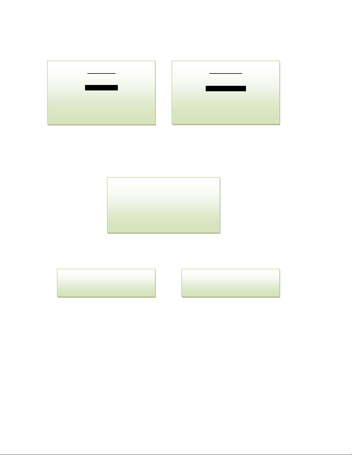
• Access the MAIN MENU by pressing the MENU key.
• Advance the reverse shade cursor using the ARROW keys to highlight CALIBRATION.
• Press the ENTER key to select the highlighted menu option.
• Select ZERO CALIBRATE. The following display appears
Allow the zero gas to flow through the transmitter until a stable oxygen reading is obtained. This may
take from several minutes to a few hours. It is highly recommended to monitor oxygen trend on a chart
recorder to ensure that the oxygen reading has stabilized; evidenced by a horizontal trend.
Press the ENTER key to ZERO calibrate or MENU key to abort and return to SAMPLING mode.
Pressing ENTER, the analyzer will complete ZERO calibration and return to Sample mode. If you press
ENTER when the oxygen reading is outside of the acceptable zero offset limit, the analyzer will fail ZERO
calibration and return to the Sample mode.
Note: The maximum zero calibration adjustment permitted is approximately 60% of the lowest full scale
range available. Thus the maximum zero calibration adjustment or zero offset for this analyzer is 0.6%
oxygen.
Factory Default Zero
The software will eliminate any previous zero calibration adjustment and display the actual signal output
of the sensor at a specified oxygen concentration. For example, assuming a zero gas is introduced, the
display will reflect an oxygen reading representing basically zero oxygen contents. However, a small
oxygen reading contributed by the sensor and electronics may be seen (typically less than 2% of the full
scale of the most sensitive range of the transmitter. This feature allows the user to test the integrity of
the sample system, sensor and electronics without removing the sensor from the sensor housing.
MAIN MENU
SELECT RANGE
CALIBRATION
VIEW HISTORY
SYSTEM OPTIONS
CONFIG ALARMS
BYPASS ALARMS
CALIBRATION
SPAN CALIBRATE
ZERO CALIBRATE
DEFAULT SPAN
DEFAULT ZERO
OUTPUT CALIBRATE
OUTPUT SIMULATE
0.0 PPM
ZERO CALIBRATION
WAIT FOR STEADY RDG
ENTER TO CALIBRATE
MENU TO ABORT
CALIBRATION
PASSED
CALIBRATION
FAILED
Page 24
Advanced Instruments, Inc.
24
Factory Default Span
The embedded software will remove previous span calibration data and reset the SPAN adjustment to the
factory default value based on the average oxygen sensor’s signal output. For example, after factory
default span, when a span gas is introduced, the micro-processor will display oxygen reading within
+50% of the span gas value when the sensor signal output is within its specification. If the sensor’s
signal output is outside of its specification, the oxygen reading will be beyond +/-50% of the span gas
value. This feature allows the user to test the sensor’s signal output without removing it from the sensor
housing.
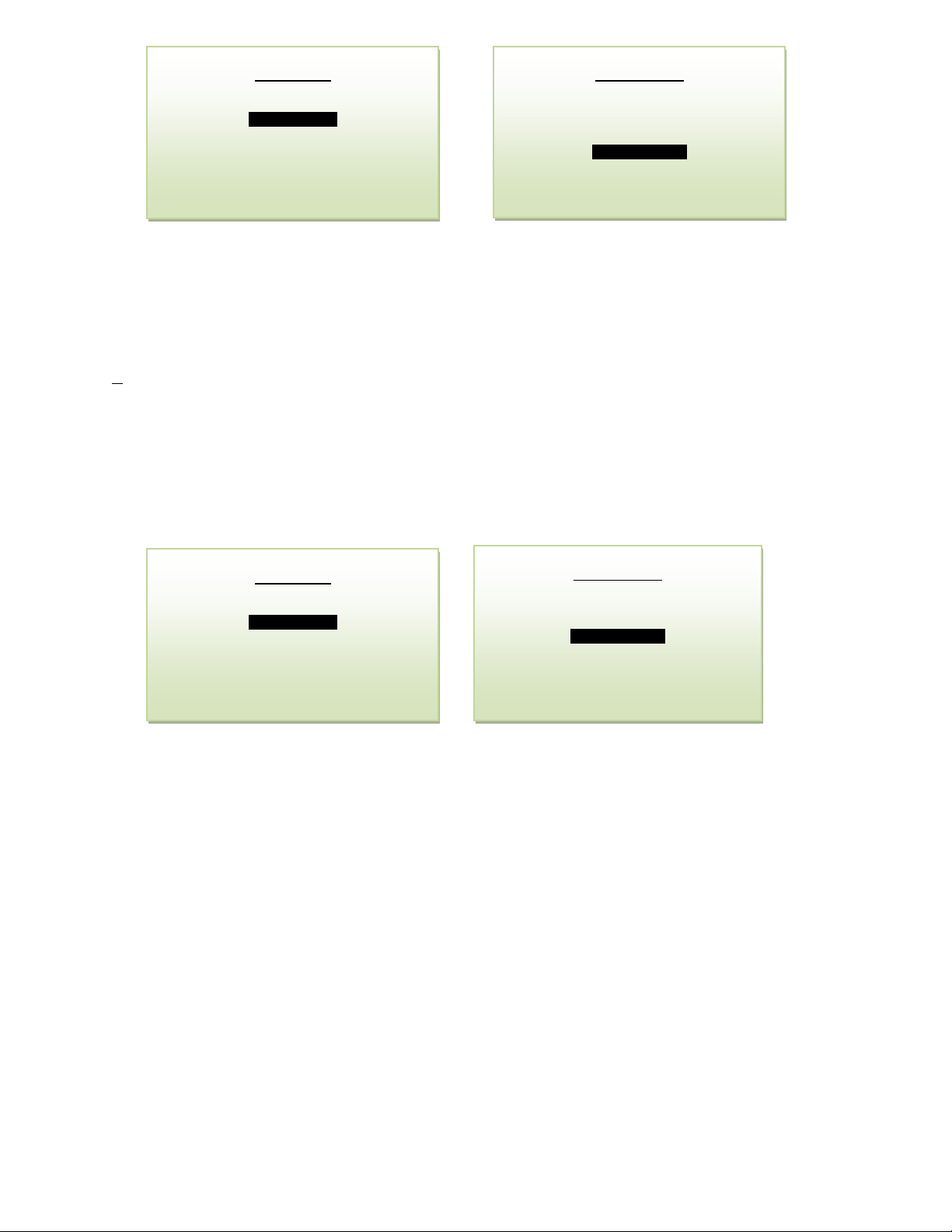
Access the MAIN MENU by pressing the MENU key.
Advance the reverse shade cursor using the ARROW keys to highlight CALIBRATION.
Press the ENTER key to select the highlighted menu option. The following display appears:
MAIN MENU
SELECT RANGE
CALIBRATION
VIEW HISTORY
SYSTEM OPTIONS
CONFIG ALARMS
BYPASS ALARMS
CALIBRATION
SPAN CALIBRATE
ZERO CALIBRATE
DEFAULT SPAN
DEFAULT ZERO
OUTPUT CALIBRATE
OUTPUT SIMULATE
MAIN MENU
SELECT RANGE
CALIBRATION
VIEW HISTORY
SYSTEM OPTIONS
CONFIG ALARMS
BYPASS ALARMS
CALIBRATION
SPAN CALIBRATE
ZERO CALIBRATE
DEFAULT SPAN
DEFAULT ZERO
OUTPUT CALIBRATE
OUTPUT SIMULATE
Page 25
Advanced Instruments, Inc.
25
Span Calibration
The analyzer is generally delivered calibrated and ready to use. However, in order to obtain reliable data,
the analyzer must be calibrated at the initial start-up and periodically thereafter. The maximum
calibration interval recommended is approximately 1-3 months, or as determined by the user’s
application.
Calibration involves adjusting the transmitter electronics gain (sensitivity) to the sensor’s signal output at
a given oxygen standard, e.g. a certified span gas with an oxygen content (balance nitrogen)
approximating 80% of the range of analysis or one range above the intended measuring range is
recommended for optimum accuracy, see Calibration and Accuracy. Calibration with ambient or
instrument air (20.9%) is recommended when installing a new sensor or when a certified gas is not
available.
The user must ascertain that the oxygen reading (actually the sensor’s signal output) has reached a
stable value within the acceptable limits before completing the span adjustment. Failure to do so will
result in an error.
• For calibration purposes, use of the AUTO SAMPLE mode is recommended. However, the user
can select the full scale MANUAL SAMPLE RANGE – for example, a span gas with an 8% oxygen
concentration with the balance nitrogen would dictate the use of the 0-10% full scale range for
calibration.
• Regulate the span gas pressure between 5-30 psig and set flow rate between 1-2 SCFH.
• Allow the span gas to flow for 1-2 minutes to purge the air trapped in the span gas line.
• Disconnect the sample gas line and connect the span gas line to the sample IN.
• The transmitter will immediately respond to the span gas. Typically, within 5-10 minutes, oxygen
reading will stabilize. To perform span calibration
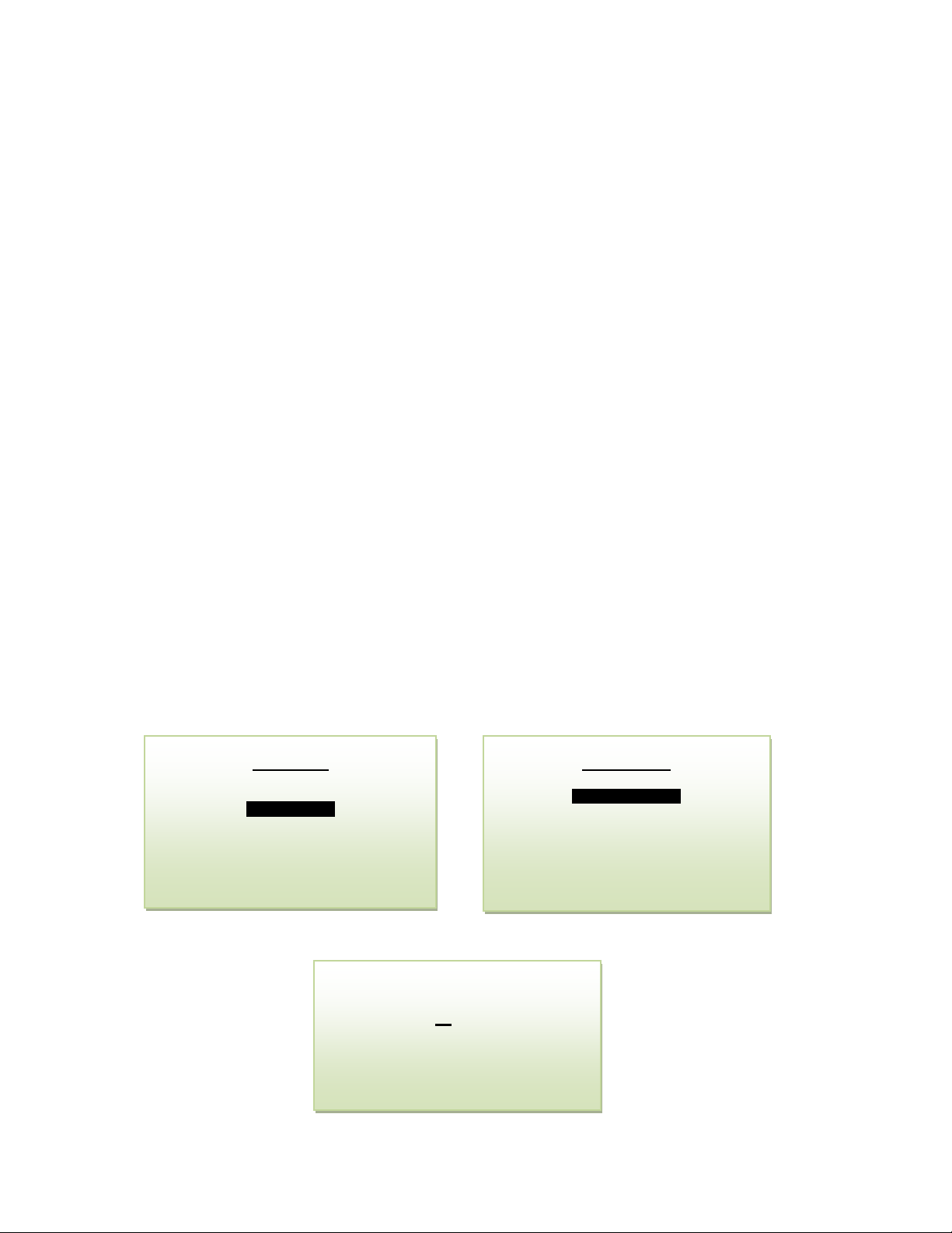
• Access the MAIN MENU by pressing the MENU key.
• Advance the reverse shade cursor using the ARROW keys to highlight CALIBRATION.
• Press the ENTER key to select the highlighted menu option.
• Advance the reverse shade cursor using the ARROW keys to highlight SPAN CALIBRATE and
press ENTER.
• The following displays appear:
Use the ARROW keys to enter the first digit of the span value.
MAIN MENU
SELECT RANGE
CALIBRATION
VIEW HISTORY
SYSTEM OPTIONS
CONFIG ALARMS
BYPASS ALARMS
CALIBRATION
SPAN CALIBRATE
ZERO CALIBRATE
DEFAULT SPAN
DEFAULT ZERO
OUTPUT CALIBRATE
OUTPUT SIMULATE
SPAN GAS VALUE
20.9
PRESS UP OR DOWN
TO CHANGE VALUE
ENTER TO SAVE
MENU TO RETURN
Page 26

Advanced Instruments, Inc.
26
Press the ENTER key to advance the underline cursor right or press the MENU key to advance
the underline cursor left.
Repeat steps until the complete span value has been entered. After entering the span value,
the following display appears
Allow approximately 5-10 min for oxygen to stabilize and the press ENTER to complete span gas
calibration
Both the Zero Calibrate and Span Calibrate functions result in the following displays showing either
'PASSED CALIBRATION" OR "FAILED CALIBRATION"
In either case, the analyzer returns to the SAMPLING mode and resume sampling.
Disconnect the span gas line and replace it with sample gas line.
Wait 10-15 minutes to ensure the reading is stable and then proceed to sampling.
20.9%
SPAN CLAIBRATION
WAIT FOR STEADY RDG
ENTER TO CALIBRATE
MENU TO ABORT
CALIBRATION
PASSED
CALIBRATION
FAILED
Page 27
Advanced Instruments, Inc.
27
Adjustment of 4-20 mA Analog Output
In rare instances the 4-20mA signal output may not agree to the reading displayed by the LCD. This
feature enables the user to adjust the 20mA signal output should the LCD display not agree.
Note: Adjust the 4mA signal output with the OUTPUT CALIBRATE option described above.
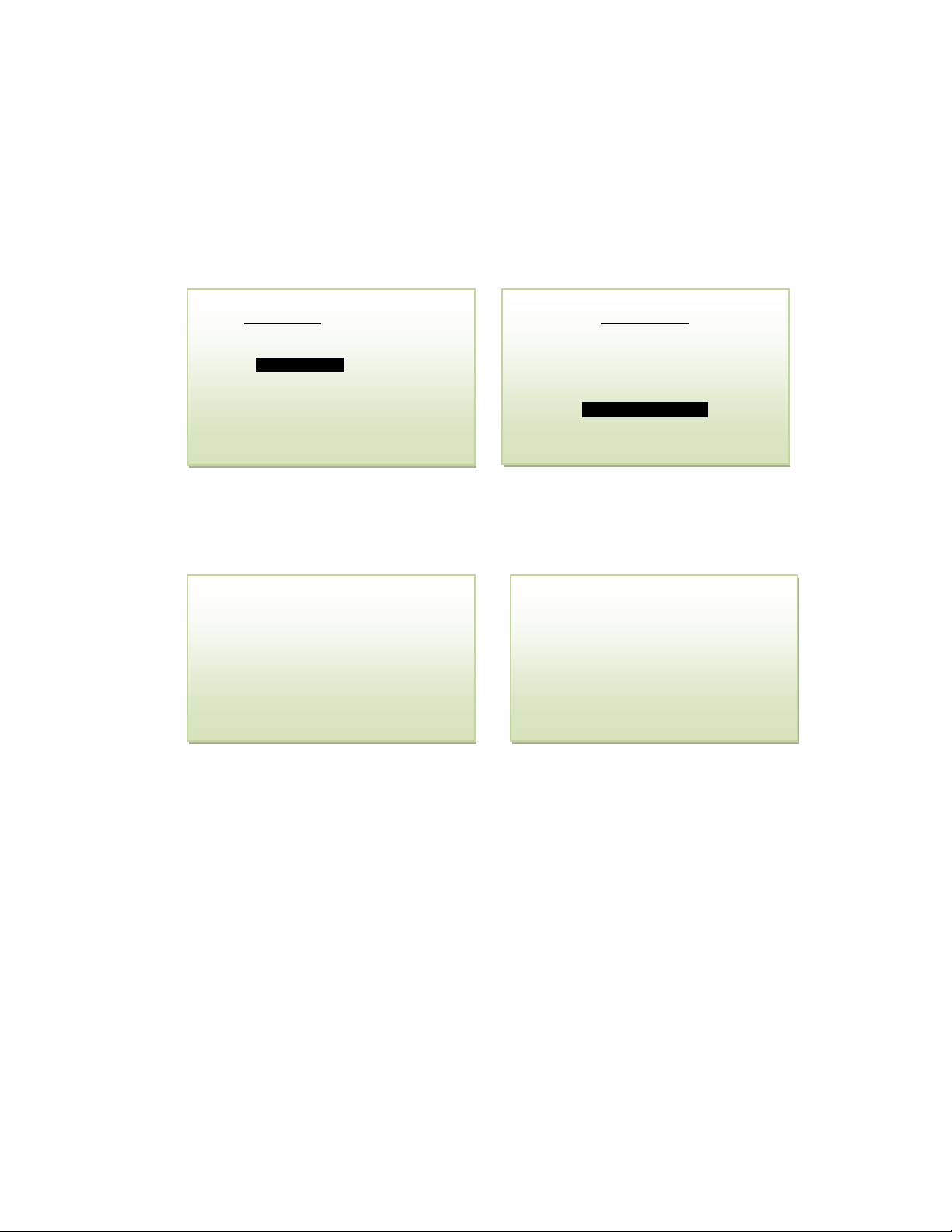
1. Access the MAIN MENU by pressing the MENU key.
2. Advance the reverse shade cursor using the ARROW keys to highlight CALIBRATION.
3. Press the ENTER key to select the highlighted menu option.
The following displays appear:
4. Advance the reverse shade cursor using the ARROW keys to highlight OUTPUT CALIBRATE.
5. Press the ENTER key to select the highlighted menu option.
The following display appears
6. While measuring the output value on a meter, use the UP/DOWN keys to adjust the value up
or down until the meter reads 20mA.
7. Save the adjustment value by pressing the ENTER key or abort by pressing the MENU key.
8. While measuring the output value on a meter, use the UP/DOWN keys to adjust the value up
or down until the meter reads 4mA.
9. Save the adjustment value by pressing the ENTER key or abort by pressing the MENU key.
The system returns to the SAMPLING mode.
MAIN MENU
SELECT RANGE
CALIBRATION
VIEW HISTORY
SYSTEM OPTIONS
CONFIG ALARMS
BYPASS ALARMS
OUTPUT SPAN
4MA ADJUST
PRESS UP OR DOWN
TO ADJUST OUTPUT
ENTER TO SAVE
MENU OT ABORT
OUTPUT SPAN
20MA ADJUST
PRESS UP OR DOWN
TO ADJUST OUTPUT
ENTER TO SAVE
MENU OT ABORT
CALIBRATION
SPAN CALIBRATE
ZERO CALIBRATE
DEFAULT SPAN
DEFAULT ZERO
OUTPUT CALIBRATE
OUTPUT SIMULATE
Page 28
Advanced Instruments, Inc.
28
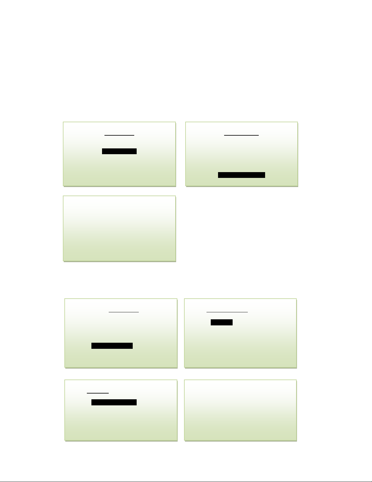
Output Simulate
Forces the 4-20mA output to a specified value. The corresponding value (mA) is shown in steps of 5% of
span.
1. Access the MAIN MENU by pressing the MENU key.
2. Advance the reverse shade cursor using the ARROW keys to highlight CALIBRATION.
3. Press the ENTER key to select the highlighted menu option.
4. Advance the reverse shade cursor using the ARROW keys to highlight OUTPUT SIMULATE.
5. Press the ENTER key to select the highlighted menu option and using the UP or DOWN
ARROW keys the output increments or decrements in steps of 5% of span.
Alarms
The transmitter is equipped with two programmable alarm relays. The two alarms set points are user
adjustable and can be set either as LOW/HIGH, LOW/LOW or HIGH/HIGH.
CALIBRATION
SPAN CALIBRATE
ZERO CALIBRATE
DEFAULT SPAN
DEFAULT ZERO
OUTPUT CALIBRATE
OUTPUT SIMULATE
MAIN MENU
SELECT RANGE
CALIBRATION
VIEW HISTORY
SYSTEM OPTIONS
CONFIG ALARMS
BYPASS ALARMS
OUTPUT SIMULATE
0% SPAN
4.0MA
PRESS UP OR DOWN
TO ADJUST OUTPUT
ENTER/MENU TO EXIT
CONFIG ALARMS
ALARM 1
ALARM 2
PULSING = OFF
AUDIBLE = NO
BYPASSED = NO
MAIN MENU
SELECT RANGE
CALIBRATION
VIEW HISTORY
SYSTEM OPTIONS
CONFIG ALARMS
BYPASS ALARMS
ALARM 1 SETPOINT
02.0
PRESS UP OR DOWN
TO CHANGE VALUE
ENTER TO SAVE
MENU TO RETURN
ALARM 1
SETPOINT = 2.0%
MODE = LOW
DELAY = 1.0 MIN
LATCHING = NO
FAILSAFE = NO
ENABLED = YES
Page 29
Advanced Instruments, Inc.
29
Alarm Delays
Alarm delay option allows the user to ignore the alarm should a sudden short spike in the oxygen reading
occurs.
Alarm Bypass
The alarms bypass feature allows the user to bypass the alarm during trouble shooting/repair or test run.
However, once the alarm bypass is selected, alarm will remain disabled even if the oxygen reading is
over/under the alarm set point. The alarm will re-arm itself only after the fault condition has been
reverted.
The alarms are automatically disabled during SPAN/ZERO calibration.
The relays are rated at 1A @ 230V.
CAUTION; When using these relays, do not exceed the recommended rating.
Standby
The transmitter has no special storage requirements.
The sensor should remain inside of the sensor housing and connected to the electronics during storage
periods. Before turning the transmitter OFF, ensure that sample system is purged with clean ambient air.
This will keep the sample system clean and would be ready to use again when required with very short
down time.
Store the transmitter with power OFF at a safe location and away from a direct heating source.
If storing for an extended period of time, protect the transmitter from dust, heat and moisture.
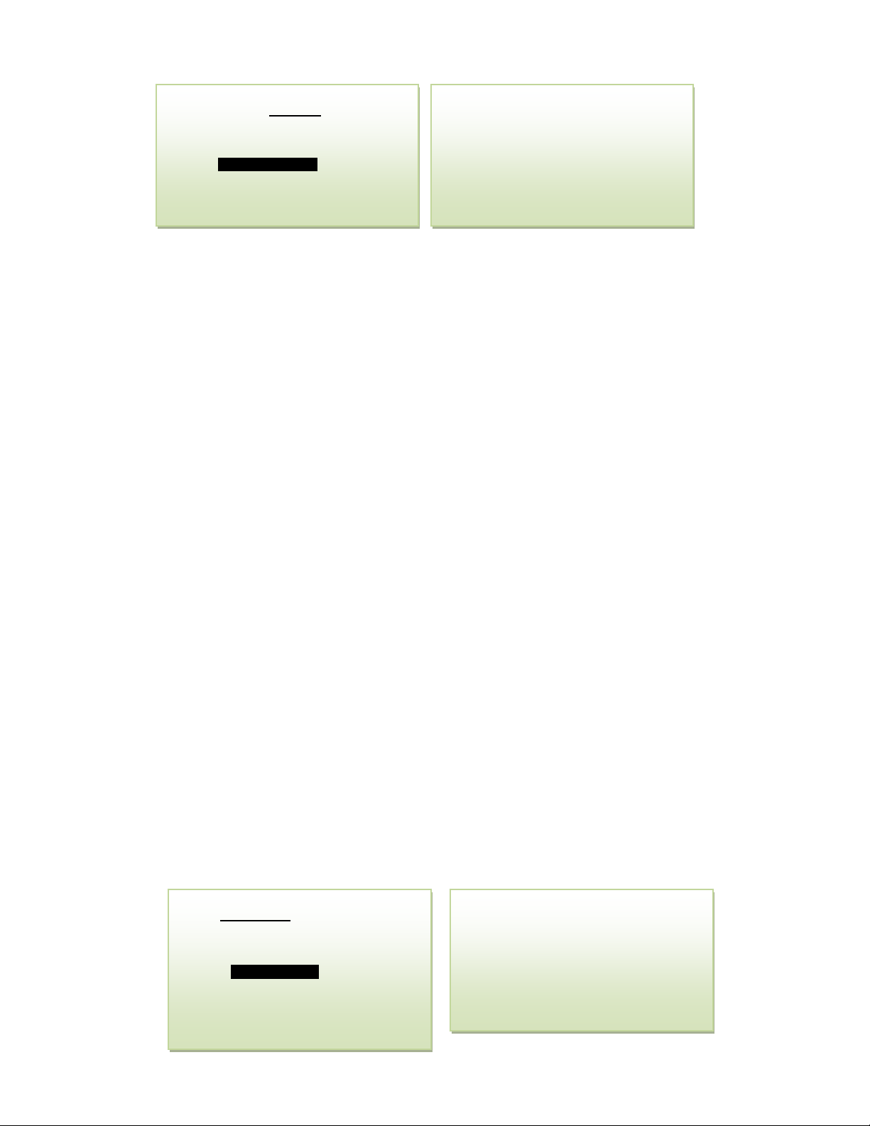
History
View History displays the highest, lowest and average gas concentration measured during the time period
shown in the upper right hand corner of the screen.
MAX TEMP displays the highest temperature recorded since the first calibration of the sensor.
SNSR TIMR displays the number of days since the sensor was first calibrated.
SPAN TIMR displays the number of days since the last span calibration.
DELAY IN MINUTES
01.0
PRESS UP OR DOWN
TO CHANGE VALUE
ENTER TO SAVE
MENU TO RETURN
ALARM 1
SETPOINT = 1 PPM
MODE = LOW
DELAY = 1.0 MIN
LATCHING = NO
FAILSAFE = NO
ENABLED = YES
HISTORY
0 DAYS
MAX PPM = 0.1
MIN PPM = 0.0
AVG PPM = 0.0
MAX TEMP = 64.0
SNSR TIMR = 0 DAYS
SPAN TIMR = 0 DAYS
MAIN MENU
SELECT RANGE
CALIBRATION
VIEW HISTORY
SYSTEM OPTIONS
CONFIG ALARMS
BYPASS ALARMS
Page 30

Advanced Instruments, Inc.
30
Security
PASSCODE LOCK prevents unauthorized access to the analyzer’s menus, functions and settings. Selecting
PASSCODE LOCK will put the analyzer in sample mode and accessing the menus will require a valid
passcode.
SET PASSCODE changes the security passcode.
AUTO LOCK enables or disables auto passcode locking. If no keys are pressed for a time period
exceeding the auto lock delay, the analyzer will automatically passcode lock. Setting the duration to 0
minutes disables auto locking.
SYSTEM OPTIONS
SECURITY
DEFINE RANGES
SHOW NEGATIVE = NO
SECURITY
PASSCODE LOCK
SET PASSCODE
AUTO LOCK = OFF
SECURITY
PASSCODE LOCK
SET PASSCODE
AUTO LOCK =OFF
ENTER NEW PASSCODE
1111
PRESS UP OR DOWN
TO CHANGE VALUE
ENTER TO SAVE
MENU TO RETURN
MAIN MENU
SELECT RANGE
CALIBRATION
VIEW HISTORY
SYSTEM OPTIONS
CONFIG ALARMS
BYPASS ALARMS
SECURITY
PASSCODE LOCK
SET PASSCODE
AUTO LOCK=OFF
DELAY IN MINUTES
00
PRESS UP OR DOWN
TO CHANGE VALUE
ENTER TO SAVE
MENU TO RETURN
Page 31
Advanced Instruments, Inc.
31
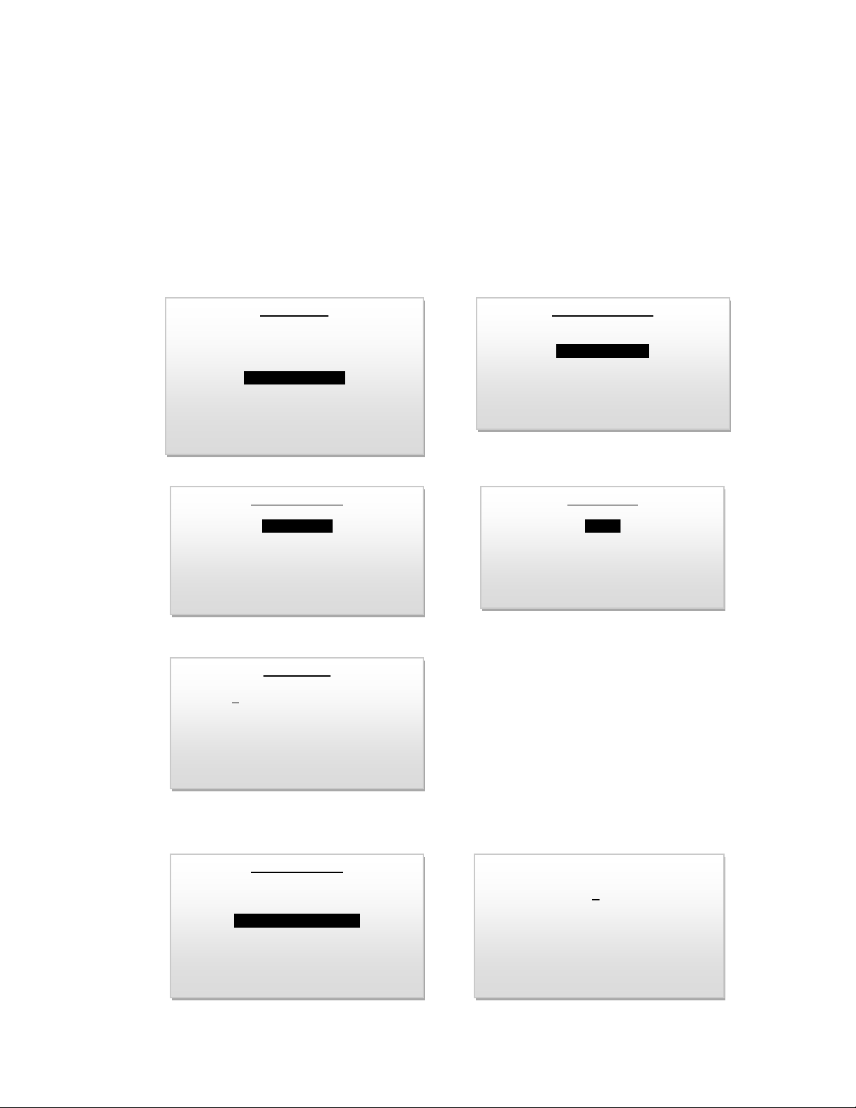
Define Ranges
EDIT RANGE sets the full-scale range values. A new range may not exceed the highest or lowest factorysupplied ranges. A new range must be at least 20% greater than the next lower range and at least 20%
lower than the next higher range.
DFLT RANGE sets a default range. If no keys are pressed for a time period exceeding the default range
delay (DFLT DELAY), the analyzer will automatically change ranges to the default range. Setting the
default range to off disables default ranging.
DFT DELAY sets the default delay.
OUT RANGE unlocks or locks the analog output to a specific range. The analog output will only be locked
on the set range while the analyzer is in auto ranging mode. Manual ranging will cause the analog output
range to follow the display range. Setting the output range to UNLOCKED will cause the analog output
range to follow the display range, regardless of auto/manual ranging mode.
SYSTEM OPTIONS
SECURITY
DEFINE RANGES
SHOW NEGATIVE = NO
MAIN MENU
SELECT RANGE
CALIBRATION
VIEW HISTORY
SYSTEM OPTIONS
CONFIG ALARMS
BYPASS ALARMS
DEFINE RANGES
EDIT RANGE
DFLT RANGE = OFF
DFLT DELAY = 10 MIN
OUT RANGE = UNLOCKED
EDIT RANGE
1-1 %
2-5%
3- 10%
4- 25%
PPM RANGE
00020
PRESS UP OR DOWN
TO CHANGE VALUE
ENTER TO SAVE
MENU TO RETURN
DEFINE RANGES
EDIT RANGE
DFLT RANGE = OFF
DFLT DELAY = 10 MIN
OUT RANGE = UNLOCKED
DELAY IN MINUTES
10
PRESS UP OR DOWN
TO CHANGE VALUE
ENTER TO SAVE
MENU TO RETURN
Page 32

Advanced Instruments, Inc.
32
Modbus Communication
SLAVE ID: Sets the network ID (address) of the analyzer. A valid ID is between 1 and 247. Each device
on the Modbus network must have a unique ID for the network to operate properly.
BAUD: Sets the network communication baud rate: 9600 or 19200 bites per sec. All devices on the
Modbus network must operate at the same baud rate.
PARITY: Sets the communication byte error detection method: NONE, ODD, EVEN. This setting must
match with the setting used by the Modbus master.
Sampling Procedure
Following calibration, the transmitter returns automatically to the SAMPLE mode.
Select the desired sampling mode - Auto or if Manual, the range that provides maximum resolution – as
described above.
Use metal tubing to transport the sample gas to the transmitter.
The main consideration is to eliminate air leaks which can affect oxygen measurements above or below
the 20.9% oxygen concentration in ambient air - ensure the sample gas tubing connections securely
connected
For sample gases under positive pressure the user must provide a means of controlling the inlet pressure
between 5-30 psig and the flow of the sample gas between 1-5 SCFH, a flow rate of 1-2 SCHF is
recommended.
For sample gases under atmospheric or slightly negative pressure an optional sampling pump is
recommended to push the sample through the transmitter. Ensure that sample flow is within the
recommended range; if necessary, use a flow control valve to set the sample flow.
Assure the sample is adequately vented for optimum response and recovery – and safety.
Allow the oxygen reading to stabilize for approximately 10 minutes at each sample point.
Avoid drawing a vacuum on the sensor that exceeds 14” of water column pressure.
Avoid excessive flow rates above 5 SCFH which generate backpressure on the sensor.
Avoid the collection of particulates, liquids or condensation collect on the sensor that could block the
diffusion of oxygen into the sensor.
Page 33

Advanced Instruments, Inc.
33
System Options
• Set security; password protected operation
• Define ranges; choose a range between two ranges, for example, 2% full scale instead
of 5% full scale.
• Display signal below 0.000%; negative signal, yes or no.
To enter password, from system option menu, select SECURITY, then enter four-digit PASS CODE,
numeral numbers only and press ENTER. Then select AUTO LOCK option and enter the number of
minutes after which access to MENU options will be locked (access allowed only after entering the PASS
CODE).
In the event PASS CODE is lost, enter the factory default PASS CODE 2855 to access the MENU and then
re-enter the new PASS CODE.
Choosing the option to display negative number will allow the user to see the display below 0.00 but the
output will be locked at 4 mA.
Page 34

Advanced Instruments, Inc.
34
6. Maintenance
Generally, cleaning the electrical contacts or replacing filter elements is the extent of the maintenance
requirements of this transmitter.
Sensor Replacement
Periodically, the oxygen sensor will require replacement. The operating life is determined by a number of
factors that are influenced by the user and therefore difficult to predict. The Features & Specifications
define the normal operating conditions and expected life of the standard sensor utilized by the GPR2500A transmitter. Expected sensor life is inversely proportional to changes in oxygen concentration,
pressure and temperature. To replace sensor, follow the procedure outlined in the section “Operation”
Serviceability: Except for replacing the oxygen sensor, there are no parts inside the transmitter for the
operator to service. Only trained personnel with the authorization of their supervisor should conduct
maintenance.
Caution: DO NOT open the oxygen sensor. The sensor contains a corrosive liquid electrolyte that could
be harmful if touched or ingested, refer to the Material Safety Data Sheet contained in the Owner’s
Manual. Avoid contact with any liquid or crystal type powder in or around the sensor or sensor housing,
as either could be a form of electrolyte. Leaking sensors should be disposed of in accordance with local
regulations.
Page 35

Advanced Instruments, Inc.
35
7. Spare Parts
Recommended spare parts for the GPR-2500A Oxygen Transmitter:
Item No.
Description
GPR-11-32-4
Oxygen Sensor (GPR-2500A)
XLT-11-24-4
Oxygen Sensor (GPR-2500A)
Other spare parts:
Item No.
Description
A-2079
Bracket Sensor Mounting
CONN-1014-6
Cable Sensor with Female Socket
FITN-1018
Connector SS 1/8” MNPT to 1/8” Tube
FITN-1039
Elbow SS 1/8”
A-2221
Housing Flow Adaptor
MTR-1016
Meter Digital Panel LCD Backlight
A-2781
Nut Sensor Retaining
A-1161-AIS-2Rev C4
PCB Assembly Main / Display
A-1166-AIS-2 Rev
J2
PCB Assembly Power Supply / Interconnections
Page 36

Advanced Instruments, Inc.
36
8. Trouble Shooting
Symptom
Possible Cause
Recommended Action
No Display
Reading does not reflect
expected values
Inadequate power supply
Incorrect polarity of power input
Sensor was not calibrated at similar
vent pressure, flow rate and
temperature anticipated in the sample
gas stream
Ensure that power to the transmitter is
within the recommended range
Ensure that the polarity of the input
power matches with the designation on
the power input terminal
Recalibrate the analyzer at ambient
conditions that resemble with sampling
conditions.
Unable to span calibrate the
sensor with ambient air or
with a certified span gas
Indication sensor signal output is
outside the acceptable limit
Replace sensor, see Section 6 Maintenance.
Slow response time
Erratic oxygen reading
No oxygen reading
Longer sample line
Low sample flow
Liquid covering sensing membrane
Presence of interference gases.
Damaged sensor cable and or sensor
housing bring signal to the PCB
No signal from sensor possibly due to
defective/used up sensor or broken
wire connections from sensor cable or
sensor housing to PCB
Reduce the sample tubing to a
minimum, set sample flow between 1-2
SCFH, gently remove any liquid that
might have accumulated on the
sensor’s sensing side. If condensable
components are present, use a
coalescing filter upstream of sensor
Consult factory, interfering gas such as
H2S might need to removed from the
sample gas, replace sensor.
Replace sensor cable
Replace upper section of sensor
housing
Check for any physical damage to
sensor cable and or sensor housing.
Use a voltmeter and check continuity
from sensor housing to the Molex
connector (the connector from sensor
housing to the PCB)
Check sensor signal output in air (by
using a voltmeter (set to measure
micro-amp current). Sensor signal in
air must be within 40-60 uA (%
sensor) or 450-900 uA (PPM sensor).
High oxygen reading
Inadequate control of pressure and
sample flow rate
Excessive back pressure on sensor
caused by high sample flow
Set sample gas pressure within
recommended range of 5-30 PSIG
Set sample flow between 1-2 SCFH
Vent sample to atmosphere
Page 37

Advanced Instruments, Inc.
37
Cannot perform Zero
calibration
Obstruction on sample vent line
Abnormality in span gas
Leak in sample/zero gas line
Inadequate zero gas flow
Contaminated zero gas
Attempting to Zero calibrate
prematurely
If venting sample to a vent pipe with
pressure above atmosphere, consult
factory for recommendations.
Qualify span gas with a secondary
analyzer
Check for any leakage in sample/zero
gas line
Check the integrity of zero gas
Set the gas flow rate between 1-2
SCFH
Allow sufficient time for the oxygen
reading to stabilize before attempting
Zero calibration.
Page 38

Advanced Instruments, Inc.
38
9. Warrant Policy
What is covered:
Any defect in material and workmanship from normal use in accordance with the Owner’s Manual.
This warranty applies to all transmitter purchased worldwide. Advanced Instruments Inc. reserves the
right in its sole discretion to invalidate this warranty if the serial number does not appear on the
transmitter.
For how long:
One year from shipment by manufacturer or purchase from a distributor with proof of purchase.
Who is warranted:
This warranty is limited to the first customer who submits a claim. Under no circumstances will the
warranty extend to more than one customer.
What we will do:
If your Advanced Instruments Inc. transmitter is defective with respect to material and workmanship, we
will repair it or, at our option, replace it at no charge to you.
If we choose to replace your Advanced Instruments Inc. transmitter, we may use new or reconditioned
replacement parts.
If we choose to replace your Advanced Instruments Inc. transmitter, we may replace it with a new or
reconditioned one of the same or upgraded design.
Limitations:
Implied warranties, including those of fitness for a particular purpose and merchantability (an unwritten
warranty that the product is fit for ordinary use), are limited to one year from the date of shipment by
manufacturer or purchase from a distributor with proof of purchase.
Advanced Instruments Inc. will not pay for: loss of time; inconvenience; loss of use of your Advanced
Instruments Inc. transmitter or property damage caused by your Advanced Instruments Inc. transmitter
or its failure to work; any special, incidental or consequential damages; or any damage resulting from
alterations, misuse or abuse; lack of proper maintenance; unauthorized repair or modification of the
transmitter; affixing of any attachment not provided with the transmitter or other failure to follow the
Owner’s Manual.
Some states and provinces do not allow limitations on how an implied warranty lasts or the exclusion of
incidental or consequential damages, so the above exclusions may not apply to you. This warranty gives
you specific legal rights, and you may also have other rights which vary from state to state and province
to province.
What is not covered:
This warranty does not cover installation; defects resulting from accidents; damage while in transit to our
service location; damage resulting from alterations, misuse or abuse; lack of proper maintenance;
unauthorized repair or modification of the transmitter; affixing of any attachment not provided with the
transmitter; fire, flood, or acts of God; or other failure to follow the Owner’s Manual.
Page 39

Advanced Instruments, Inc.
39
Sole Warranty
This warranty is the only one we will give on your Advanced Instruments Inc. transmitter, and it sets
forth all our responsibilities regarding your Advanced Instruments Inc. transmitter.
There are no other express warranties.
How to obtain warranty service:
Do-It-Yourself-Service:
Call Advanced Instruments Inc. at 909-392-6900 between 8:00am and 5:00pm Pacific Time weekdays.
Trained technicians will assist you in diagnosing the problem and arrange to supply you with the required
parts.
Service from Distributors:
If warranty service is provided by a distributor, Advanced Instruments Inc. will provide all required parts
under warranty at no charge to you, but the distributor is an independent business and may render a
service charge for their services. Advanced Instruments Inc. will not reimburse you or otherwise be
responsible for those charges.
Return to Advanced Instruments Inc.:
You may obtain warranty service by returning you transmitter, postage prepaid to:
Advanced Instruments Inc.
2855 Metropolitan Place
Pomona, Ca 91767 USA
Be sure to pack the transmitter securely. Include your name, address, telephone number, proof of date
of purchase and a description of the operating problem. After repairing or, at our option, replacing your
Advanced Instruments Inc. transmitter, we will ship it to you at no cost for parts and labor.
Your choice of any one of the service options described above is your exclusive remedy under this
warranty.
Page 40

Advanced Instruments, Inc.
40
10. Material Safety Data Sheet [MSDS]
Product Identification
Product Name
Oxygen Sensor Models CAD, GPR, PSR, SAF, 67013
Synonyms
Galvanic Fuel Cell, Electrochemical Transducer
Manufacturer
Analytical Industries Inc.
2855 Metropolitan Place, Pomona, CA 91767 USA
Emergency Phone Number
909-392-6900
Preparation / Revision Date
January 1, 1995
Notes
Oxygen sensors are sealed, contain protective coverings and in normal
conditions do not present a health hazard. Information applies to
electrolyte unless otherwise noted.
Specific Generic Ingredients
Carcinogens at levels > 0.1%
None
Others at levels > 1.0%
Potassium Hydroxide, Lead
CAS Number
Potassium Hydroxide = KOH 1310-58-3, Lead = Pb 7439-92-1
Chemical (Synonym) and
Family
Potassium Hydroxide (KOH) - Base, Lead (Pb) - Metal
Physical Properties
Boiling Point Range
100 to 115 C
Melting Point Range
KOH -10 to 0 C, Lead 327 C
Freezing Point
-40 to 0 C
Molecular Weight
KOH = 56, Lead = 207
Specific Gravity
1.09 @ 20 C
Vapor Pressure
Not applicable
Vapor Density
Not applicable
pH
> 14
Solubility in H2O
Complete
% Volatiles by Volume
None
Evaporation Rate
Similar to water
Appearance and Odor
Colorless, odorless aqueous solution
General Requirements
Use
Potassium Hydroxide - electrolyte, Lead - anode
Handling
Rubber or latex gloves and safety glasses
Storage
Indefinitely
Fire and Explosion Data
Flash and Fire Points
Not applicable
Page 41

Advanced Instruments, Inc.
41
Flammable Limits
Not flammable
Extinguishing Method
Not applicable
Special Fire Fighting Procedures
Not applicable
Unusual Fire and Explosion
Hazards
Not applicable
Reactivity Data
Stability
Stable
Conditions Contributing to
Instability
None
Incompatibility
Avoid contact with strong acids
Hazardous Decomposition
Products
None
Conditions to Avoid
None
Spill or Leak
Steps if material is released
Sensor is packaged in a sealed protective plastic bag, check the sensor
inside for electrolyte leakage.
If the sensor leaks inside the protective plastic bag or inside a
transmitter sensor housing do not remove it without rubber or latex
gloves and safety glasses and a source of water.
Flush or wipe all surfaces repeatedly with water or wet paper towel.
Use a fresh towel each time.
Waste Disposal Method
In accordance with federal, state and local regulations for battery
disposal
Health Hazard Information
Primary Route(s) of Entry
Ingestion, eye and skin contact
Exposure Limits
Potassium Hydroxide - ACGIH TLV 2 mg/cubic meter; Lead - OSHA PEL
.05 mg/cubic meter
Effects of Exposure -
Ingestion
Electrolyte could be harmful or fatal if swallowed. Oral LD50 (RAT) =
2433 mg/kg
Eye
Electrolyte is corrosive and eye contact could result in permanent loss
of vision.
Skin
Electrolyte is corrosive and skin contact could result in a chemical
burn.
Inhalation
Liquid inhalation is unlikely.
Symptoms
Eye contact - burning sensation; Skin contact - soapy slick feeling.
Medical Conditions Aggravated
None
Carcinogenic Reference Data
NTP Annual Report on Carcinogens - not listed; LARC Monographs not listed; OSHA - not listed
Other
Lead is listed as a chemical known to the State of California to cause
birth defects or other reproductive harm.
Emergency First Aid
Ingestion
Do not induce vomiting; Give plenty of cold water; Seek medical
Page 42

Advanced Instruments, Inc.
42
attention immediately.
Skin Contact
Wash affected area repeatedly with plenty of water; Remove
contaminated clothing; If burning persists, seek medical attention.
Eye Contact
Flush repeatedly with plenty of water for at least 15 minutes; Seek
medical attention immediately.
Inhalation
Liquid inhalation is unlikely.
Special Protection Information
Ventilation Requirements
None
Eye
Safety glasses
Hand
Rubber or latex gloves
Respirator Type
Not applicable
Other Protective Equipment
None
Special Precautions
Precautions
Do not remove the sensor’s protective Teflon and PCB coverings; Do
not probe the sensor with sharp objects; Wash hands thoroughly after
handling; Avoid contact with eyes, skin and clothing; Empty sensor
body may contain hazardous residue.
Transportation
Not applicable
Product Identification
Product Name
Oxygen Sensor Models XLT
Synonyms
Galvanic Fuel Cell, Electrochemical Transducer
Manufacturer
Analytical Industries Inc.
2855 Metropolitan Place, Pomona, CA 91767 USA
Emergency Phone Number
909-392-6900
Preparation / Revision Date
January 1, 1995
Notes
Oxygen sensors are sealed, contain protective coverings and in normal
conditions do not present a health hazard.
Information applies to electrolyte unless otherwise noted.
Specific Generic Ingredients
Carcinogens at levels > 0.1%
None
Others at levels > 1.0%
Acetic Acid, Lead
CAS Number
Acetic Acid = 64-19-7, Lead = Pb 7439-92-1
Chemical (Synonym) and
Family
Acetic Acid (CH3CO2H) - Acid, Lead (Pb) - Metal
Physical Properties
Boiling Point Range
100 to 117 C
Melting Point Range
Acetic Acid = not applicable, Lead 327 C
Freezing Point
-40 to -10 C
Molecular Weight
Acetic Acid = not applicable, Lead = 207
Specific Gravity
1.05 @ 20 C
Page 43

Advanced Instruments, Inc.
43
Vapor Pressure
11.4 @ 20 C
Vapor Density (air = 1)
2.07
pH
2-3
Solubility in H2O
Complete
% Volatiles by Volume
None
Evaporation Rate
Similar to water
Appearance and Odor
Colorless, vinegar-like odor aqueous solution
General Requirements
Use
Acetic Acid - electrolyte, Lead - anode
Handling
Rubber or latex gloves; Safety glasses
Storage
Indefinitely
Fire and Explosion Data
Flash and Fire Points
Not applicable
Flammable Limits
Not flammable
Extinguishing Method
Not applicable
Special Fire Fighting Procedures
Not applicable
Unusual Fire and Explosion
Hazards
Not applicable
Reactivity Data
Stability
Stable
Conditions Contributing to
Instability
None
Incompatibility
Avoid contact with strong bases
Hazardous Decomposition
Products
Emits toxic fumes when heated
Conditions to Avoid
Heat
Spill or Leak
Steps if material is released
Sensor is packaged in a sealed protective plastic bag, check the sensor
inside for electrolyte leakage. If the sensor leaks inside the protective
plastic bag or inside an transmitter sensor housing do not remove it
without rubber or latex gloves, safety glasses and a source of water.
Flush or wipe all surfaces repeatedly with water or wet paper towel.
Use a fresh towel each time.
Waste Disposal Method
In accordance with federal, state and local regulations for battery
disposal.
Health Hazard Information
Primary Route(s) of Entry
Ingestion, eye and skin contact
Exposure Limits
Acetic Acid - ACGIH TLV / OSHA PEL 10 (TWA); Lead - OSHA PEL .05
mg/cubic meter
Effects of Exposure -
Page 44

Advanced Instruments, Inc.
44
Ingestion
Electrolyte could be harmful or fatal if swallowed; Oral LD50 (RAT) =
6620 mg/kg
Eye
Electrolyte is corrosive and eye contact could result in permanent loss
of vision.
Skin
Electrolyte is corrosive and skin contact could result in a chemical
burn.
Inhalation
Liquid inhalation is unlikely.
Symptoms
Eye contact - burning sensation; Skin contact - burning sensation.
Medical Conditions Aggravated
None
Carcinogenic Reference Data
NTP Annual Report on Carcinogens - not listed; LARC Monographs not listed; OSHA - not listed
Other
Lead is listed as a chemical known to the State of California to cause
birth defects or other reproductive harm. Lead acetate formed as the
sensor is used is listed as a chemical known to the State of California
to cause cancer.
Emergency First Aid
Ingestion
Do not induce vomiting; Give plenty of cold water or if available milk;
Seek medical attention immediately.
Skin Contact
Wash affected area repeatedly with plenty of water; Remove
contaminated clothing; If burning persists, seek medical attention.
Eye Contact
Flush repeatedly with plenty of water for at least 15 minutes; Seek
medical attention immediately.
Inhalation
Liquid inhalation is unlikely.
Special Protection Information
Ventilation Requirements
None
Eye
Safety glasses
Hand
Rubber or latex gloves
Respirator Type
Not applicable
Other Protective Equipment
None
Special Precautions
Precautions
Do not remove the sensor’s protective Teflon and PCB coverings; Do
not probe the sensor with sharp objects; Wash hands thoroughly after
handling; Avoid contact with eyes, skin and clothing; Empty sensor
body may contain hazardous residue.
Transportation
Not applicable
 Loading...