

Page 1
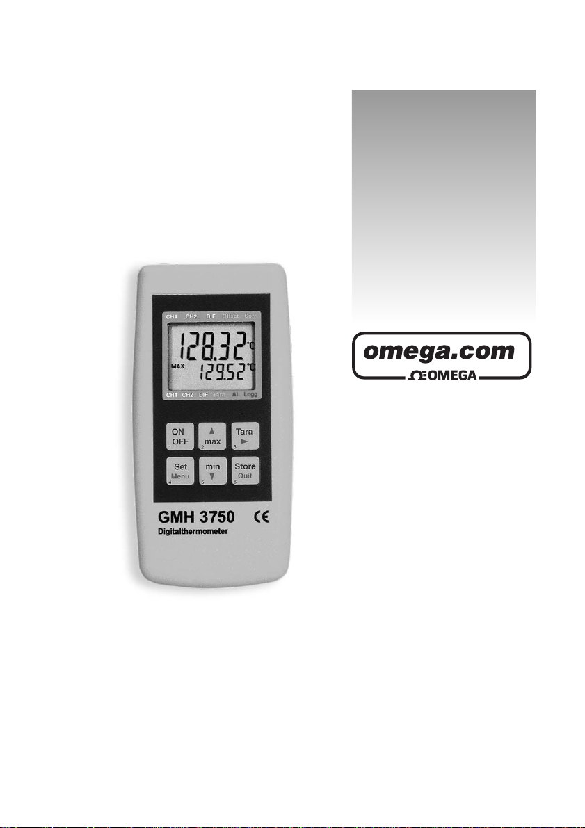
User’s Guide
Shop on line at
®
®
www.omega.com
e-mail: [email protected]
GMH3750
Precision Thermometer
For Pt100 4-Wire Temperature Probes
Page 2

OMEGAnet®On-Line Service Internet e-mail
®
®
www.omega.com [email protected]
Servicing North America:
USA: One Omega Drive, P.O. Box 4047
ISO 9001-Certified Stamford, CT 06907-0047
Canada: 976 Bergar
TEL: (203) 359-1660 FAX: (203) 359-7700
e-mail: [email protected]
Laval (Quebec) H7L 5A1
TEL: (514) 856-6928 FAX: (514) 856-6886
e-mail: [email protected]
For immediate technical or application assis tance:
USA and Kanada: Sales Service: 1-800-826-6342 / 1-800-TC-OMEGA
Mexico and TEL: (001) 800-TC-OMEGA FAX: (001) 203-359-7807
Latin America: En Español: (001) 203-359-7803
Customer Service: 1-800-622-2378 / 1-800-622-BEST
Engineering Service: 1-800-872-9436 / 1-800-USA-WHEN
e-mail: [email protected]
Servicing Europe:
Germany Daimlerstrasse 26
and Austria:
Benelux: Postbus 8034, 1180 LAAmstelveen, The Netherlands
Czech Republic: Fryštátská 184, 733 01 Karviná
France: 11, rue Jacques Cartier, 78280 Guyancourt
United Kingdom: One Omega Drive, River Bend Technology Centre
ISO 9002-Certified Northbank, Irlam, Manchester, M44 5BD, United Kingdom
D-75392 Deckenpfronn
TEL: 49 (07056) 9398-0 FAX: 49 (07056) 9398-29
Toll free in Germany: 0800 82 66 342
e-mail: [email protected]
TEL: (31) 20 347 2121 FAX: (31) 20 6434643
Toll free in Benelux: 0800-0993344
e-mail: [email protected]
TEL: 420 (59)6 311 899 FAX: 420 (59)6 311 114
e-mail: [email protected]
TEL: (33) 0-1 61 37 29 00 FAX: (33) 1 30 57 54 27
Toll free in France: 0800-466 342
e-mail: [email protected]
TEL: +44(0) 161 777 6611 FAX: +44(0) 161 777 6622
Toll free in England: 0800 488 488
e-mail: [email protected]
It is the policy of OMEGA to comply with all worldwide safety and EMC/EMI regulations that apply.
OMEGA is constantly pursuing certification of its products to the European New Approach Directives. OMEGA will add
the CE mark to every appropriate device upon certification.
The information contained in this document is believed to be correct, but OMEGA Engineering, Inc. accepts no liability
for any errors it contains, and reserves the right to alter specifications without notice.
WARNING: These products are not designed for use in, and should not be used for, patient-connected applications.
This device is marked with the international caution symbol. It is important to read the Setup Guide before installing or
commissioning this device as the guide contains important information relating to safety and EMC.
Page 3

Table of Contents
Chapter Page
Chapter 1 In General....................................................................................4
1.1 Safety Instructions........................................................................4
1.2 Operating And Maintenance.........................................................4
1.3 Connections .................................................................................5
1.4 Display Elements..........................................................................6
1.5 Pushbuttons..................................................................................6
Chapter 2 Device Configuration .................................................................7
2.1 Set Configuration:Generic Settings.............................................7
2.2 Set Alarm: Settings Of Alarm Function.........................................8
2.3 Set Logger: Configuration Of Logger Function.............................9
2.4 Set Clock:Setting Of Real Time Clock.........................................9
Chapter 3 Some Basics Of Precision Temperature Measuring .............10
Chapter 4 Special Functions.....................................................................12
4.1 Display Resolution .....................................................................12
4.2 User Sensor Curve ('Lin USEr')..................................................12
4.3 Zero Displacement ('Offset').......................................................12
4.4 Scale Correction ('Scale')...........................................................13
4.5 Output .......................................................................................13
4.5.1 Interface - Base Address ('Adr.').................................................13
4.5.2 Analogue Output – Scaling with DAC.0 and DAC.1....................14
4.6 Alarm ....................................................................................15
4.7 Real Time Clock .........................................................................15
Abschnitt 5 Operation Of Logger................................................................16
5.1 "Func-Stor" :Storing Single Measurements...............................16
5.2 "Func-CYCL" : Automatic Recording
with Selectable Logger-Cycle-Time............................................17
Chapter 7 Probe pin assignment..............................................................20
Chapter 8 Calibration Services.................................................................20
Chapter 9 Specification.............................................................................21
3
Page 4

Precision Thermometer GMH3750
Chapter 1 In General
1.1 Safety Instructions
This device has been designed and tested in accordance to the safety regulations for
electronic devices.
However, its trouble-free operation and reliability cannot be guaranteed unless the
standard safety measures and special safety advises given in this manual will be
adhered to when using it.
1. Trouble-free operation and reliability of the device can only be guaranteed if it is not
subjected to any other climatic conditions than those stated under "Specification".
2. Transporting the device from a cold to a warm environment condensation may
result in a failure of the function. In such a case make sure the device temperature
has adjusted to the ambient temperature before trying a new start-up.
3. The circuitry has to be designed most carefully if the device should be connected to
other devices. Internal connection in third party devices (e.g. connection GND and
earth) may result in not-permissible voltages impairing or destroying the device or
another device connected.
4. Warning: Operating the device with a defective mains power supply (e.g. short
circuit from mains voltage to output voltage) ma y result in hazardous v oltages at the
device (e.g.at sensor socket).
5. Whenever there may be a risk whatsoever involved in running it, the device has to
be switched off immediately and to be marked accordingly to avoid re-starting.
Operator safety may be a risk if:
• there is visible damage to the device
• the device is not working as specified
• the device has been stored under unsuitable conditions for a longer time
In case of doubt, please return device to manufacturer for repair or maintenance.
6. Warning: Do not use these product as safety or emergency stop device, or in any
other application where failure of the product could result in personal injury or
material damage.
Failure to comply with these instructions could result in death or serious injury and
material damage.
1.2 Operating And Maintenance
• Battery Operation
The battery has been used up and needs to be replaced, if and "bAt" are
shown in lower display.
The device will, however, continue operating correctly for a certain time.
4
Page 5
Precision Thermometer GMH3750
The battery has been completely used up, if ´bAt´ is shown in the upper display.
The battery has to be taken out, when storing device above 50°C.
Hint:We recommend to remove the battery if device is not used for a longer period
of time!
• Mains Operation
Attention:When using a power supply unit please note that operating voltage has to
be 10.5 to 12 V DC. Do not apply overvoltage!! Simple 12V-power supplies often
have excessive no-load voltage.We, therefore, recommend using regulated voltage
power supplies. Trouble-free operation is guaranteed by our power supply
GNG10/3000.
Prior to connecting the plug power supply with the mains supply make sure that the
operating voltage stated at the power supply is identical to the mains voltage.
• Treat device and probes carefully. Use only in accordance with above specification.
(do not throw, hit against etc.). Protect plugs and sockets from soiling.
• To disconnect sensor plug do not pull at the cable but at the plug.
• When connecting the probe the plug will slide in smoothly if plug is entered
correctly.
• Selection of Output-Mode: The output can be used as serial interface or as
analogue output.This choice has to be done in the configuration menu.
1.3 Connections
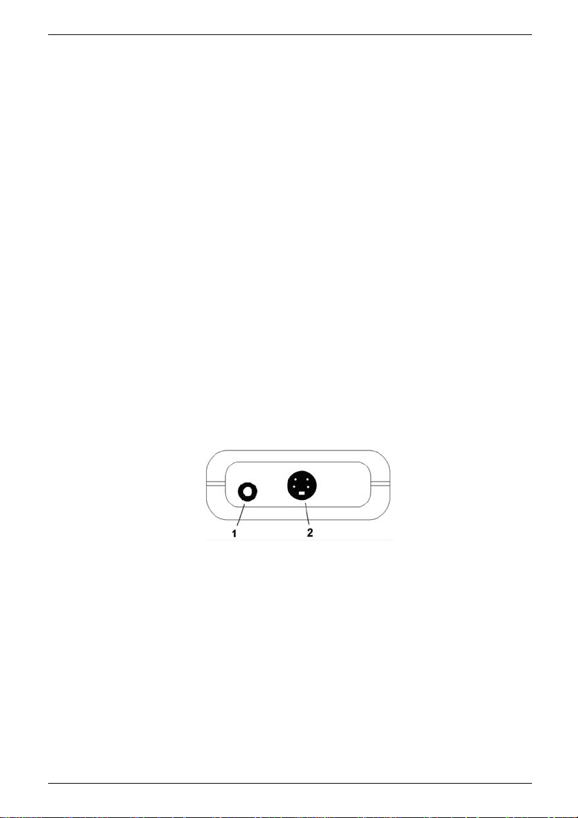
1. Output:
Operation as interface: Connect to optically isolated interface adapter (accessory:
GRS 3100 or GRS3105)
Operation as analogue output: Connection via suitable cable.
Attention: The output mode has to be configured (p.r.t 2.7) and influences battery
life!
2. Probe connection Pt100 4-wire
3. The mains socket is located at the left side of the instrument.
5
Page 6
Precision Thermometer GMH3750
1.4 Display Elements
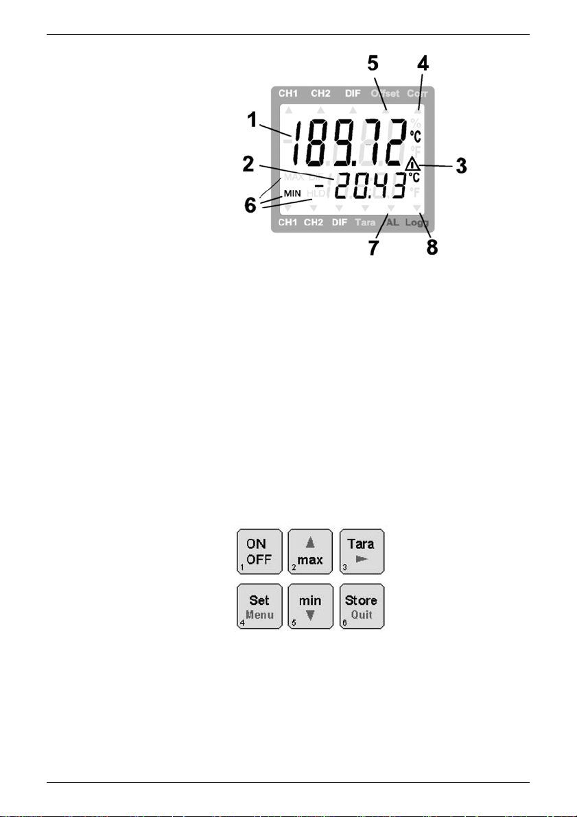
1 = Main Display: Currently measured temperature
2 = Auxiliary Display: Display of min, max or hold values
Special display elements:
3 = Warning triangle: indicates a low battery
4 = Corr-arrow: indicates that correction factor is activated
5 = Offset-arrow: indicates that zero point offset (offset) is activated
6 = Min/Max/Hold: shows if a min., max. or hold value is displayed in the
secondary display
7 = Alarm-arrow: Flashes if alarm is present
8 = Logg-arrow: Shown if logger function is selected,
flashes if cyclic logger is running
1.5 Pushbuttons
key 1: On/Off key
key 4: Set/Menu
press (Menu) for 2 sec.:configuration will activated
keys 2, 5: min/max when taking measurements:
press shortly: min. or max.measuring value will be displayed
press for 2 sec.:the min.or max. value will be deleted
up/down for configuration: to enter values or change settings
6
Page 7
Precision Thermometer GMH3750
key 6: Store/Quit
- Measurement: Hold current measuring value ('HLD' in display) or
operation of logger functions (p.r.t. Chapter 5)
- Menu: Acknowledge setting, return to measuring
key 3: When taking measurements:no function
During configuration: Selection of menu-parameter
Chapter 2 Device Configuration
Note: Some menu items will be shown depending on the actual device configuration
(e.g. there are some items disabled when the logger contains data). Please
note the hints by the menu items.
For configuration of the device press "Menu"-key (key 4) for 2 seconds, the main menu
will be shown (main display: "SEt"). Choose the desired menu branch by pressing the
"Menu"-key (key 4). By pressing "FORWARD" (key 3) the referr ing parameters can be
chosen.
The referring values are changed by pressing the keys "UP" (key 2) or "DOWN" (key 5)
(Choice of parameter: "FORWARD"). Pressing "Menu" (key 4) again will jump back to
the main menu selection and stores the settings. Use key "Quit" (key 6) to leave
configuration.
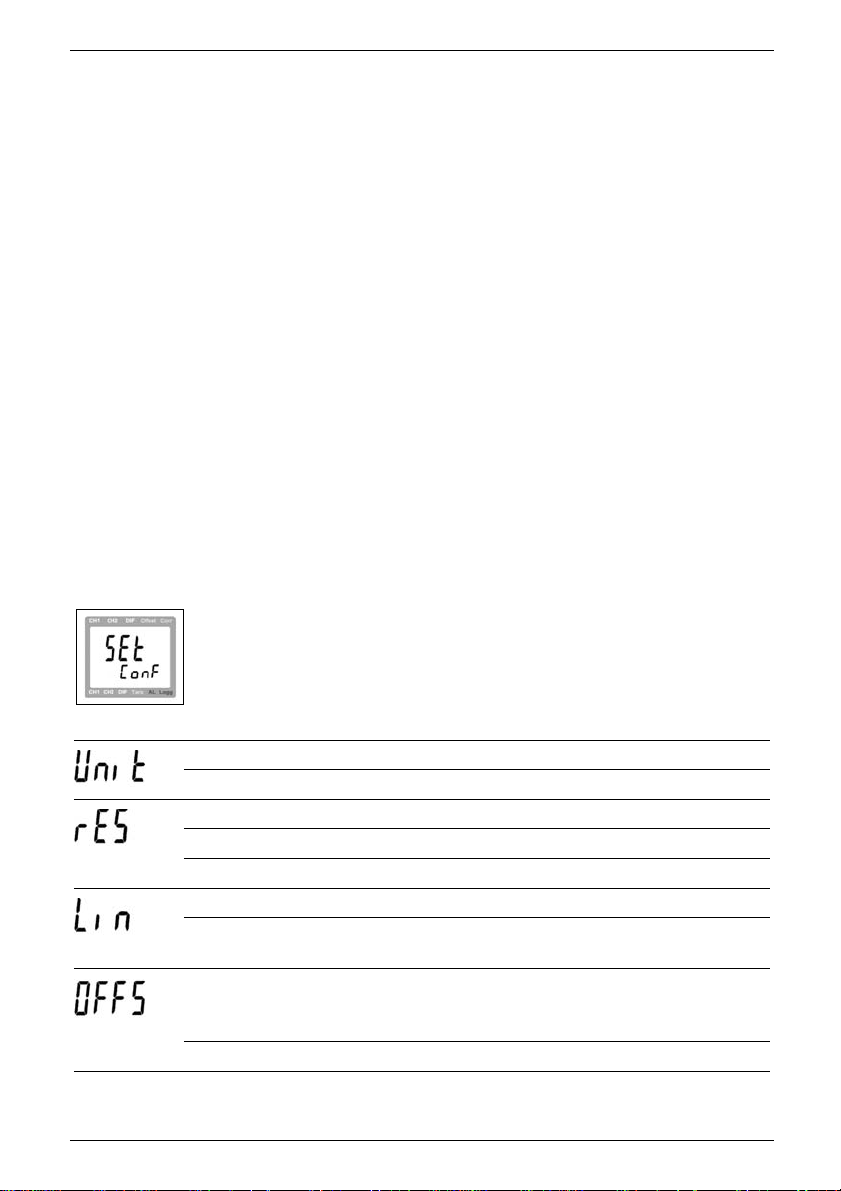
2.1 Set Configuration: Generic Settings
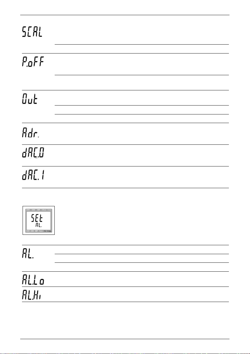
Parameter Value Meaning
°C All temperature values are in degrees Celsius
°F All temperature values are in degrees Fahrenheit
0.1° Resolution 0.1°C
0.01° Resolution 0.01°C
Auto Resolution is selected automatically
E.751 Measuring / sensor curve according to EN60751
USEr User sensor curve (Predefined to EN60751 values,
changeable by software GMHKonfig)
-2.50°C...2.50°C The zero point of the measurement will be
resp. displaced by this value to compensate for
-4.50°F...4.50°F deviations in the probe or in the measuring device.
oFF Zero displacement inactive (=0.0°)
7
Page 8
Precision Thermometer GMH3750
-2.000...2.000 The scale of the measuring will be changed by this
oFF Scale correction factor inactive (=0.000)
1...120 Power -off delay in minutes. Device will be automatically
switched off as soon as this time has elapsed if no key is
pressed/no interface communication takes place
oFF: Power-off function inactive (continuous operation, e.g.mains
operation)
oFF Function of the output: No output function, lowest power
consumption
SEr Output is serial interface
dAC Output is analogue output 0...1V
01,11...91 Base Address when Output = Serial Interface :
-200.0...850.0°C Enter desired temperature value
resp. at which the analogue output potential
-328.0...1562.0°F should be 0V
-200.0...850.0°C Enter desired temperature value
resp. at which the analogue output potential
-328.0...1562.0°F should be 1V
factor (in %) to compensate deviations of
temperature probe or measuring device
Base address of device for interface
communication.
2.2 Set Alarm: Settings Of Alarm Function
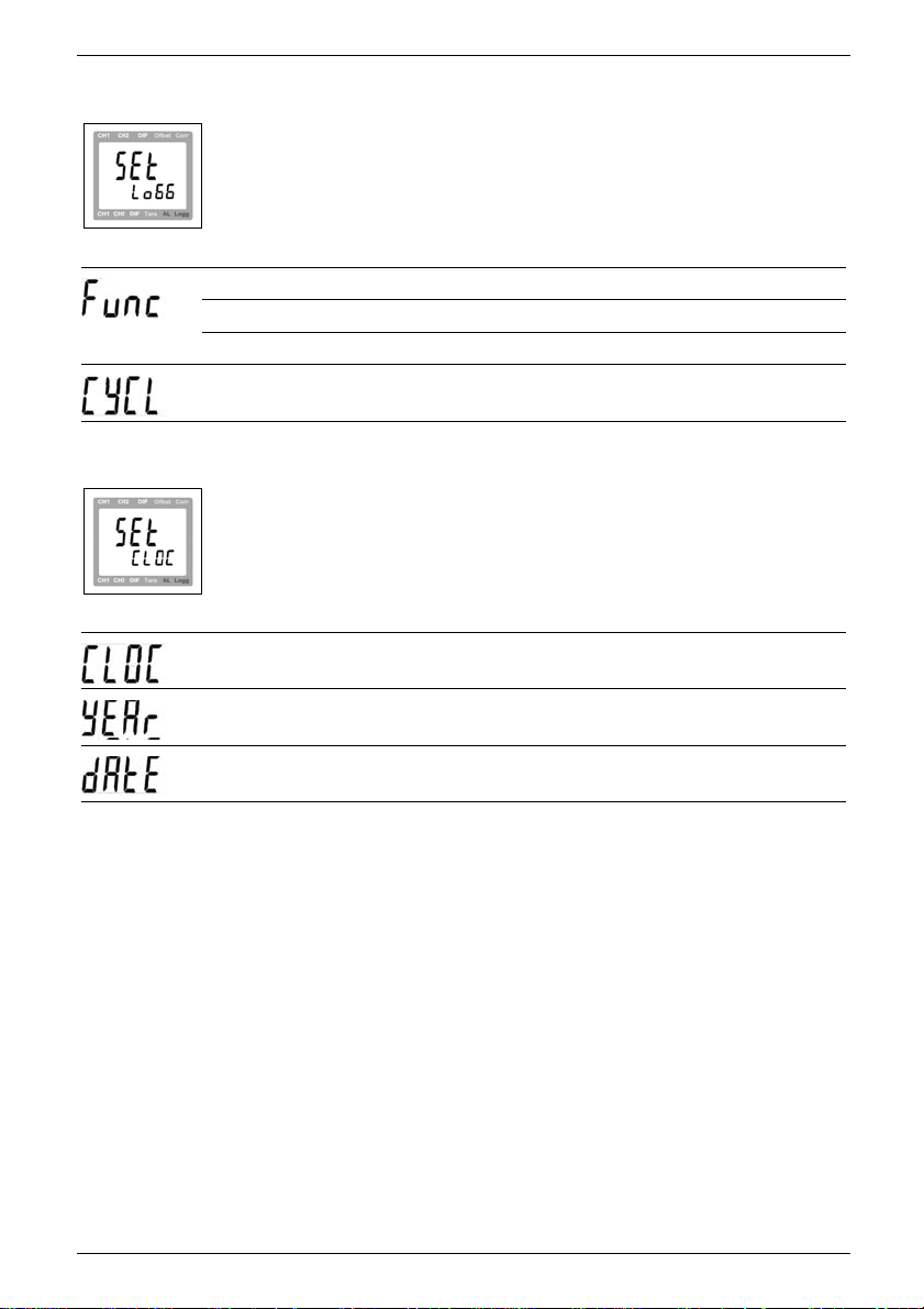
Parameter Value Meaning
on Alarm on, with horn-sound
no.So Alarm on, without horn-sound
oFF no alarm function
... AL.Hi Min alarm rail (not when AL.oFF)
AL.Lo ... Max alarm rail (not when AL. oFF)
8
Page 9
Precision Thermometer GMH3750
2.3 Set Logger: Configuration Of Logger Function
Parameter Value Meaning
CYCL Cyclic: logger function ‚cyclic logger‘
Stor Store:logger function ‚individual value logger‘
oFF no logger function
0:01... 60:00 Cycle time of cyclic logger [minutes:seconds]
2.4 Set Clock: Setting Of Real Time Clock
Parameter Value Meaning
HH:MM Clock: Setting of time hours:minutes
YYYY Year
TT.MM Date: day.month
Hint:
The settings will be set to the settings ex works, if keys ‘Set‘ and ‘Store‘ are pressed
simultaneously for more than 2 seconds.
(*) If the logger memor y contains data already, the menus/parameters marked with (*)
can not be invoked! If these should be altered the logger memory has to be cleared
before!
9
Page 10
Precision Thermometer GMH3750
Temperature ˚C
Tolerance ±˚C
Class B
1/10 DIN
Class A
1/3 DIN
0,5
0
1
1,5
-100 0 100
200
0,5
-2000-100 0 100 200 300 400 500 600 700 800
1
1,5
2
2,5
3
3,5
4
4,5
5
Temperature ˚C
Tolerance ±˚C
Class B
1/10 DIN
Class A
1/3 DIN
Chapter 3 Some Basics Of Precision Temperature Measuring
• Probe Precision/Device Precision
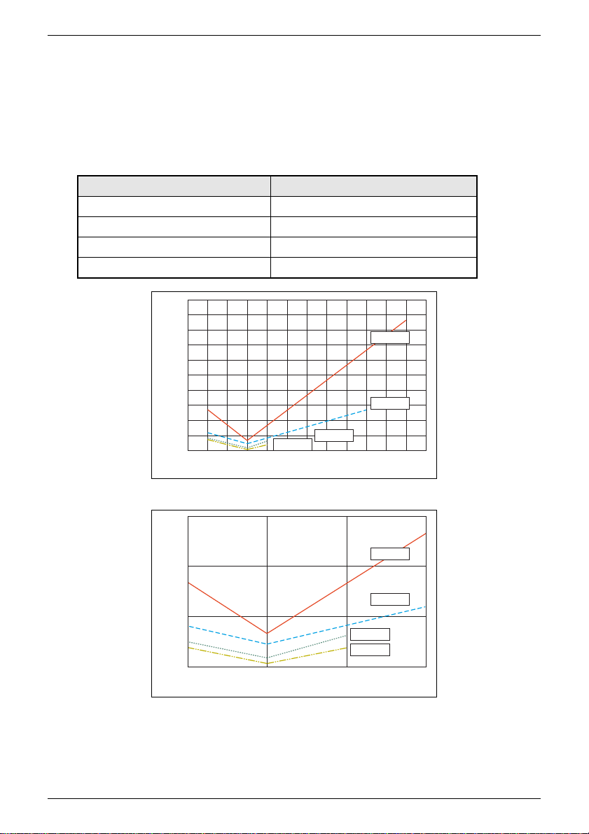
The device is very precise (please refer to technical data). To be able to use this
high precision, the connected temperature probe has to be as precise as possible,
too. The following precision classes are available as a standard at reasonable
prices (Platinum resistor thermometers according to EN60751):
Class Error ranges
B ± (0,3 + 0,005 • [temperature])
1/3 B (=1/3 DIN) ± (0,1 + 0,0017 • [temperature])
1/10 B (=1/10 DIN) ± (0,03 + 0,0005 • [temperature])
A ± (0,15 + 0,002 • [temperature])
For applications demanding higher precision than given by this classes we suggest
to adjust the device to the used probe or to get a calibration certificate for the device
combined with the probe.
10
Error over measuring range
Error over range –50...150°C
Page 11

Precision Thermometer GMH3750
Attention: if an adjusted or calibrated probe is replaced, also the adjustment or
calibration certificate has to be renewed to maintain the referring overall precision!
Be careful when buying third party temperature probes: Besides the standard
EN60751 there are some other obsolete or unusual standards on the market. If
such a probe has to be connected, the user sensor curve (have a look to the
referring chapter) can be used to adjust the instrument!
• 4-Wire-Measuring
When using resistance thermometers as the Pt100 a quite large measuring error
can be caused by inadequate cables and connections. Using 4wire measuring
avoids this kinds of errors mainly caused by unwanted resistances. It is suggested
to use suitable probes and extensions only. (For pin assignment please refer to
chapter 7).
• Heat loss caused by probe construction
Especially when measuring temperatures which deviate very much from the
ambient temperature, measuring errors often occur if the heat loss caused by the
probe is not considered. When measuring fluids therefore the probe should be
emerged sufficiently deep and be stirred continuously. When measuring gases the
probe should also emerge as deep as possible in the gas to be measured (e.g.
when measuring in channel/pipes) and the gas should flow around the probe at
sufficient flow.
• Measuring Surface Temperature
If temperature of the surface of an object has to be measured, one should pay
attention especially when measuring hot (or very cold) surfaces, that the ambient
air cools (or heats) the surface.Additionally the object will be cooled (or heated) by
the probe or the probe can have a better heat flow to the ambient temperature as to
the objects surface. Therefore specially designed surface probes should be used.
The measuring precision depends mainly on the construction of the probe and of
the physics of the surface itself .If selecting a probe try to choose one with low mass
and heat flow from sensor to handle.Ther mally conductive paste can increase the
precision in some cases.
• Allowable temperature Range Of Probes
Pt100 Sensors are defined over a wide temperature range. Depending on probe
materials and sort of sensor (e.g. hybrid sensors, wire wound resistors...) the
allowable temperature ranges ha ve to be considered. Exceeding the ranges at least
causes a wrong measuring, it may even damage the probe permanently!
Often it also has to be considered, that the temperature range is just valid for the
probe tube, (plastic-) handles can’t stand the same high temperatures. Therefore
the tube length should be selected long enough, that temperature keeps low at the
handle.
11
Page 12

Precision Thermometer GMH3750
• Self Heating
The measuring current of the instrument is just 0.3mA. Because of this comparably
low current practically no self heating effect has to be considered, even at air with
low movement the self heating is <= 0.01°C.
• Cooling by Evaporation
When measuring air temperature the probe has to be dry.Otherwise the cold due to
the evaporation causes too low measurings.
Chapter 4 Special Functions
4.1 Display Resolution
Standard setting: 'Auto', i.e. the device automatically switches over to the optimum
resolution between .01° and 0.01°.
If temperatures to be measured are near the switching threshold, a fixed resolution may
be better, e.g. for easy recording. In such a case please select the optimum resolution
manually.
4.2 User Sensor Curve ('Lin USEr')
By means of this function besides the standard conversion of resistance to temperature
following EN60751(Lin E.751) also other curves can be used. The user sensor curve
can be read and edited by the configuration software GMHKONFIG. The standard
setting ex works is also set to the EN60751 data. The curve is defined by a table with
two columns (input resistance[Ohm]/output temperature [°C]) with 50 rows.
Info: The sensor curve following EN60751 uses the international temperature scale
ITS90 and following formulas:
Temperatures <0°C: R
Temperatures >=0°C: R
(T) := 100[1+3.908310
neg
(T) := 100(1+3.908310
pos
-3
× T – 5.77510
-3
× T – 5.77510-7× T2)
-7
× T2 – 4.18310
-12
× (T–100) × T3]
4.3 Zero Displacement ('Offset')
A zero displacement can be carried out for the measured temperature:
temperature displayed = temperature measured - offset
Standard setting: 'off' = 0.0°, i.e. no zero displacement will be carried out.Together with
the scale correction (see below) this factor is mainly used to compensate for sensor
deviations.Unless the factor is set to 'off', the offset arrow in the display shows an active
zero displacement.
12
Page 13

Precision Thermometer GMH3750
4.4 Scale Correction ('Scale')
The scale of the measuring can be influenced by this setting (factor is in %):
displayed temperature[°C] = measured temperature[°C] * (1+Scal/100)
respectively
displayed temperature[°F] = (measured temperature [°F]-32°F) * (1+Scal/100) + 32°F
Standard setting: 'off' =0.000, i.e. temperature is not corrected. Together with the zero
displacement (see above) this factor is mainly used to compensate for sensor
deviations.
Unless the factor is set to 'off', the Corr arrow in the display shows an active scale
correction.
4.5 Output
The output can be used as serial interface (for GRS3100 or GRS3105 interface
adapters) or as analogue output (0-1V). If none of both is needed, we suggest to switch
the output off, because battery life then is extended.
4.5.1 Interface - Base Address ('Adr.')
By using an electrically isolated interface converter GRS3100 or GRS3105 (accessory)
the device can be connected to a PC.With the GRS3105 it is possible to connect up to 5
instruments to a single interface (please also refer to GRS3105-manual). As a
precondition the base addresses of all devices must not be identical. In case several
devices will be connected via one interface make sure to configure the base addresses
accordingly. In order to avoid transmission errors, there are several security checks
implemented (e.g.CRC).
The following standard software packages are available for data transfer:
• EBS9M : 9-channel software to record and display the measuring values
• EASYCONTROL : Universal multi-channel software (EASYBUS-, RS485-, and/or
GMH3000-operation possible) for real-time recording and presentation of
measuring data in the ACCESS
In case you want to develop your own software we offer a GMH3000-development
package including
• an universally applicable 32bit Windows functions library ('GMH3000.DLL') with
documentation that can be used by all 'serious' programming languages.
• Programming examples for Visual Basic 6.0™, Delphi 1.0™, Testpoint™,
Labview™
Note: The measuring and range values read via interface are always in the selected
display unit (°C/°F)!
®
-data base format.
13
Page 14
Precision Thermometer GMH3750
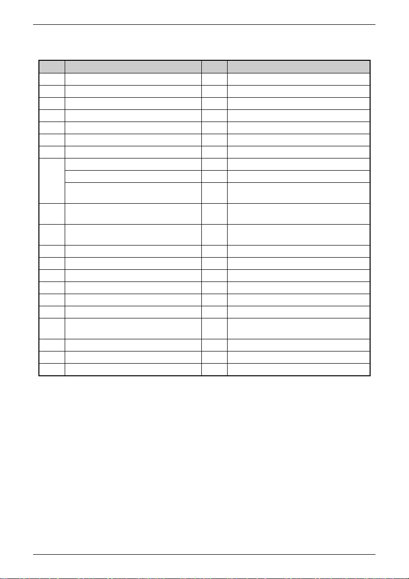
Supported interface functions:
Code Name/Funktion Code Name/Funktion
0 read nominal value 200 read min. display range
3 read system status 201 read max. display range
6 read min. value 202 read unit of display
7 read max. value 204 read decimal point of display
12 read ID-no. 208 read channel count
22 read min.alarm rail (AL.- AL.Lo) 214 read scale correction
23 read max.alarm rail (AL.- AL.Hi) 215 set scale correction
read configuration flag 216 read zero displacement
alarm function: 1; Alarm horn:3; 217 set zero displacement
32
BitLoggerOn:50;
BitCyclicLogger:51;
102 set min. alarm rail (AL. - AL.Lo) 225
103 set max. alarm rail (AL. - AL.Hi) 226
224 Logger:read data cyclic logger
Logger: read cycle time
(LoGG - CYCL)
Logger: set cycle time
(LoGG - CYCL)
160 set configuration flag (see 32) 227 Logger: start recording
174 delete min. value 228 Logger:read #of data
175 delete max. value 229 Logger: read status
176 read min measuring range 231 Logger:read stop time
177 read max measuring range 233 read Real time clock (CLOC)
178 read measuring range unit 234 set Real time clock (CLOC)
read measuring range decimal
179
point
236 Read logger memory size
180 read measuring type 240 Reset
194 set display unit 254 read program identification
199 read meas. type in display 260 Logger: read data manual logger
4.5.2 Analogue Output – Scaling with DAC.0 and DAC.1
With the DAC.0 and DAC.1 values the output can be rapidly scaled to Your efforts.
Keep in mind not to connect low-resistiv e loads to the output, otherwise the output value
will be wrong and battery life is decreased. Loads above ca 10kOhm are uncritical.
If the display exceeds the value set by DAC.1, then the device will apply 1V to the
output.
If the display falls below the value set by DAC.0, then the device will apply 0V to the
output.
In case of an error (Err.1, Err.2, no sensor, etc.) the device will apply slightly above 1V to
the output.
14
Page 15
Precision Thermometer GMH3750
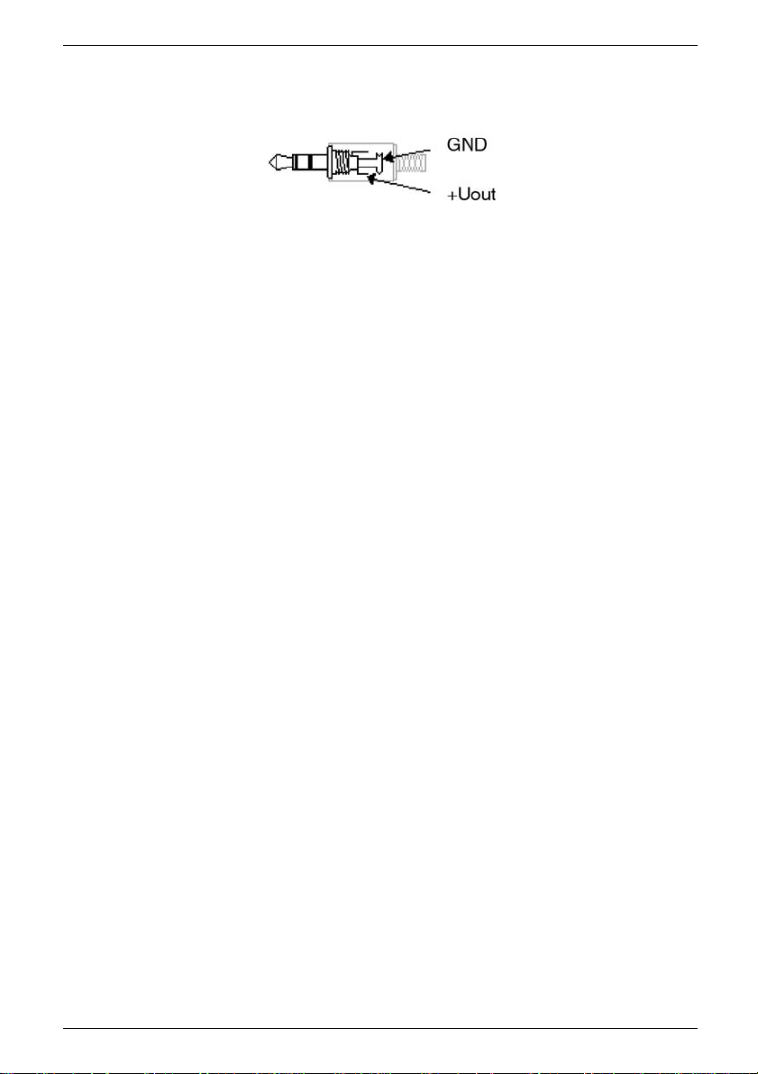
Plug wiring:
Attention!
The 3rd contact has to be left floating! Only stereo plugs are allowed!
4.6 Alarm
There are three possible settings:
Alarm off (AL. oFF), on with horn sound (AL. on), on without horn sound (AL. no.So).
Following conditions will display an alarm, when the function is activated (on or no.So):
– Value is below lower (AL.Lo) or above upper alarm rail (AL.Hi).
– Sensor error
– Low battery (bAt)
– Err.7:System error (always with sound)
In case of an alarm and when polling the interface the prio-flag is set in the returned
interface message.
4.7 Real Time Clock
The real time clock is used for the logger function:Recorded values are also containing
the point of time, when they were measured.Please check the settings when necessary.
If the battery was replaced the referring menu ‚CLOC‘ will automatically be started.
15
Page 16
Precision Thermometer GMH3710
Abschnitt 5 Operation Of Logger
The device supports two different logger functions:
"Func-Stor" : each time when „store“ (key 6) is pressed a measurement will be
recorded.
"Func-CYCL" : measurements will automatically be recorded at each interval,
which was set in the logger menu ‚CYCL‘ until the logger will be
stopped or the logger memory is full. The recording is star ted by
pressing "Store" 2 seconds.
The logger records 1 measurement result each time.
For the ev aluation of the data the softw are GSOFT3050 (V1.7 or higher) has to be used.
The software also allows easy configuration and starting of the logger.
When the logger is activated (Func Stor or Func CYCL) the hold function is no longer
available, key 6 is solely used for the operation of the logger functions.
5.1 "Func-Stor" : Storing Single Measurements
Each time when "Store" (key 6) is pressed a measurement and its time stamp will be
recorded. The recorded data can be viewed either in the display (when calling the
configuration an additional menu "REAd LoGG" is displayed, see below) or by means of
the interface and a PC with GSOFT3050-software.
Max. number of measurings: 99
A measuring contains: – current measuring value at the time of recording
– time and date of the recording
After each recording "St. XX" will be displayed for a short time. XX represents the
number of the recording.
When logger memory contains recordings already:
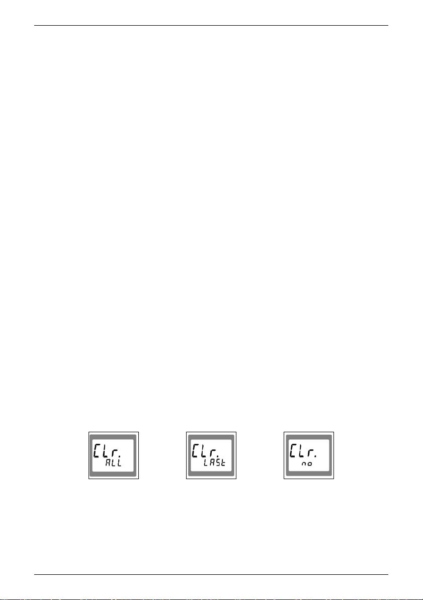
When "Store" is pressed for 2 seconds, the choice f or clearing the logger memory will be
displayed:
Clear all Clear the last Clear nothing
recordings recording (cancel menu)
The selection can be made by "UP" (key 2) and "DOWN" (key 5). "Quit" (key 6) enters
the choice.
16
Page 17
Precision Thermometer GMH3710
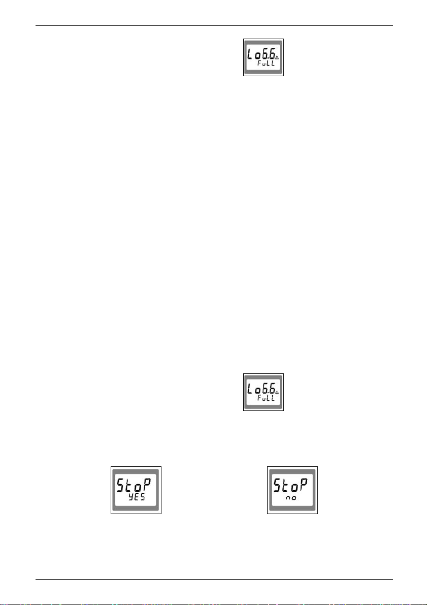
If the logger memory is full, the display will show:
Viewing Recorded Measurings
Within the "LoGG Stor" function the measurings can be viewed directly in the display not
only by means of a computer (like at "Func CYCL"): press 2 seconds "Set" (key 4):The
first menu displayed now is "rEAd LoGG" (read logger data). After pressing
"FORWARD" (key 3) the measurement recorded last will be displayed, changing
between the different data referring to the measurement also is done by pressing
"FORWARD".
Changing the measurement is done by pressing the keys "UP" or "DOWN".
5.2 "Func-CYCL" : Automatic Recording
with Selectable Logger-Cycle-Time
The Logger-Cycle-Time is selectable (p.r.t. Configuration).
For example "CYCL" = 1:00:A measuring is recorded after each 60 seconds.
Max. number of measurings: 16384
Cycle time: 0:01...60:00 (minutes:seconds, min 1s, max 1h),
selectable in the configuration
A measuring contains: – current measuring value at the time of recording
Starting a recording:
By pressing "Store" (key 6) for 2 seconds the recording will be initiated. After that the
display shows ‘St.XXXXX‘ for a short time whenever a measuring is recorded. XXXXX is
the number of the measuring 1..16384.
If the logger memory is full, the display will show:
The recording automatically will be stopped.
Stopping the recording manually:
By pressing "Store" (key 6) the recording can be stopped manually. Then the following
choice appears:
Stop the recording Do not stop the recording
The selection can be made by "UP" (key 2) and "DOWN" (key 5). "Quit" (key 6) enters
the choice.
17
Page 18
Precision Thermometer GMH3710
Note: If you try to switch off the instrument in the cyclic recording operation you will
be asked once again if the recording should be stopped.
The device can only be switched off after the recording has been stopped!
The Auto-Power-Off-function is deactivated during recording!
Clear Recordings:
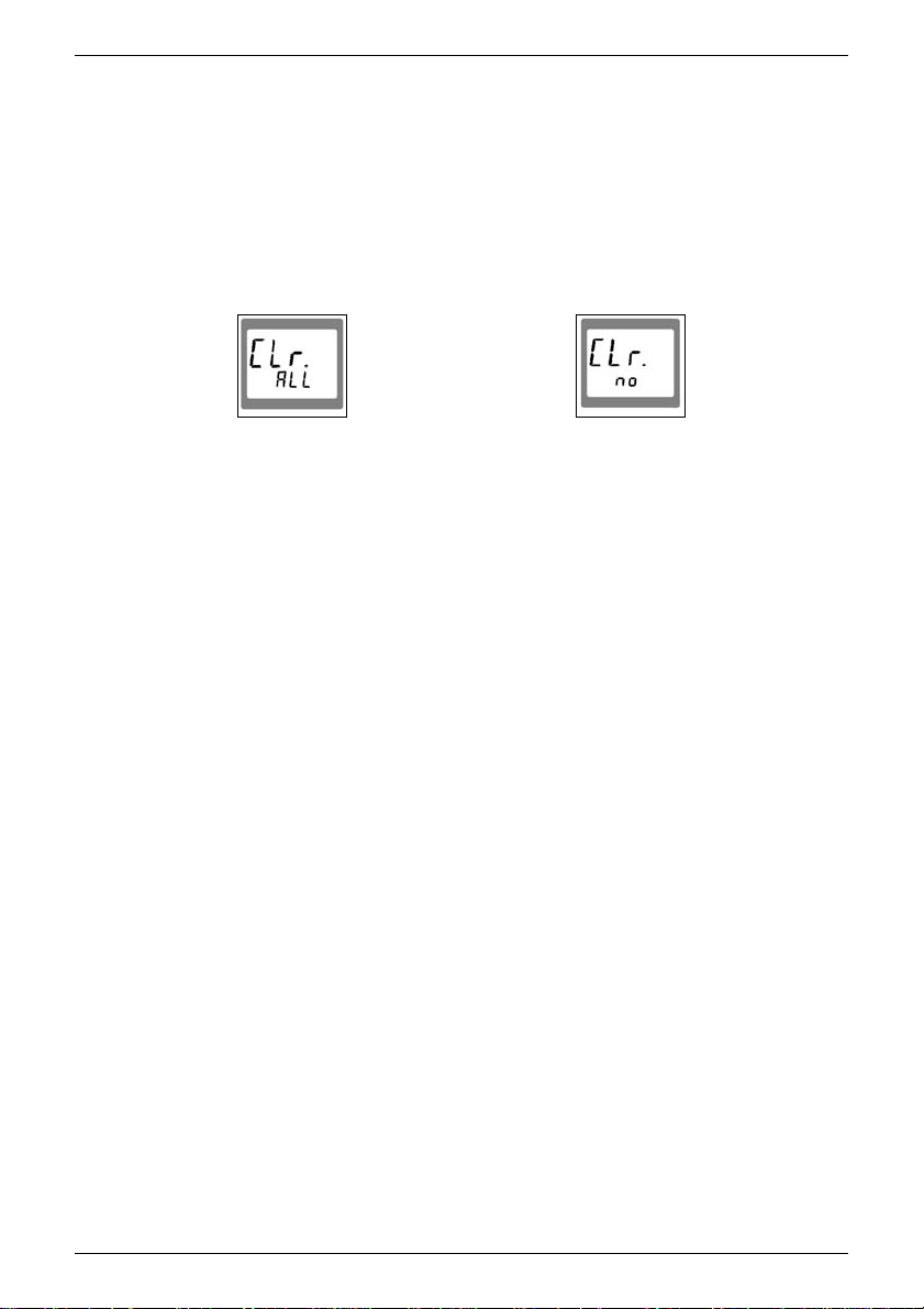
When "Store" is pressed for 2 seconds, the choice f or clearing the logger memory will be
displayed:
Clear all recordings Clear nothing (cancel menu)
The selection can be made by "UP" (key 2) and "DOWN" (key 5). "Quit" (key 6) enters
the choice.
18
Page 19
Precision Thermometer GMH3710
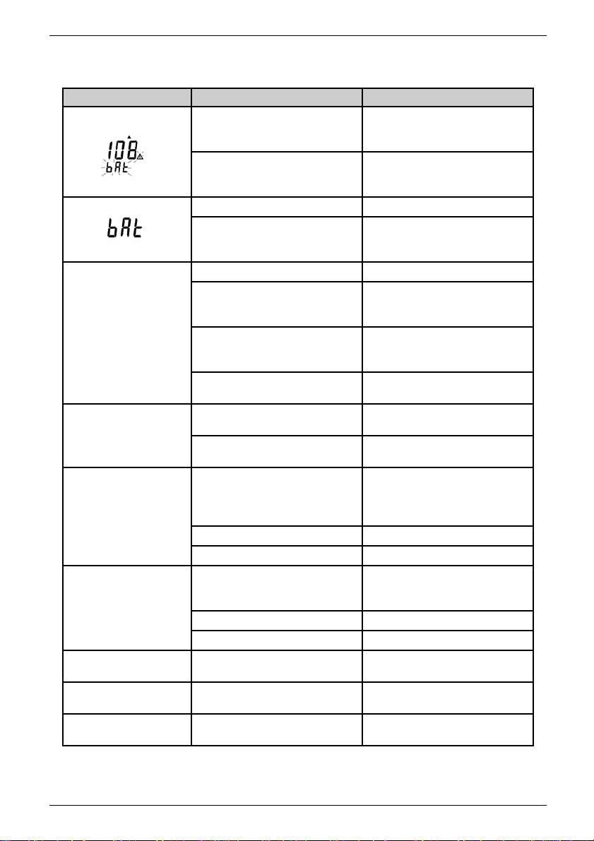
Chapter 6 Fault and System Messages
Display Meaning Remedy
low battery voltage, device will
continue to work for a short
time
If mains operation: wrong
voltage
low battery voltage replace battery
If mains operation: wrong
voltage
low battery voltage replace battery
No display
or
weird display
Device does not
react on keypress
----
Err.1
Err.2
Err.3 Value exceeding display range
Err.4 Value below display range
Err.7 system error
If mains operation: wrong
voltage
system error
device defective
Sensor error: no sensor
connected
sensor/cable or device
defective
Value exceeding measuring
range
Wrong probe connected Check probe
sensor/cable defective -> replace
Value below display range
Wrong probe connected Check probe
sensor/cable defective -> replace
replace battery
replace power supply, if fault
continues to exist:device
damaged
Check/replace power supply, if
fault continues to exist:device
damaged
Check/replace power supply, if
fault continues to exist:device
damaged
Disconnect battery or power
supply, wait some time, reconnect
return to manufacturer for
repair
Connect sensor to socket
return to manufacturer for
repair
Check:Is the value exceeding
the measuring range
specified?
->temperature too high!
Check:Is the value below the
measuring range specified?
-> temperature too low!
-> set resolution to 0.1° or
-> set resolution to 0.1° or
return to manufacturer for
repair
Auto
Auto
19
Page 20
Precision Thermometer GMH3710
Chapter 7 Probe pin assignment
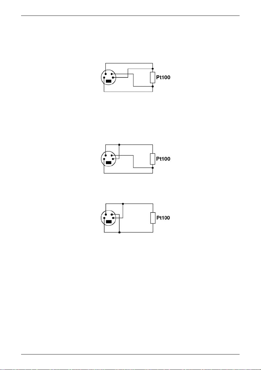
The device is constructed for the connection of a Pt100 4-wire probe.The connection is
be carried out as follows:
figure shows view upon probe jack pins
It is also possible to connect an 3- or 2-wire probe to the device.Please obser ve that in
consequence of the cable resistance a increased measuring fault will occur. The
connection of this probes should be carried out as follows:
3-wire connection
2-wire connection
Chapter 8 Calibration Services
Calibration certificates can be issued by the factory.
For this the device has to be sent to the manufacturer. Just the manufacturer can check
the factory settings and correct them if necessary.
20
Page 21

Precision Thermometer GMH3750
Precision Thermometer GMH3710
Chapter 9 Specification
Supported probes Pt100 4-wire (2-wire possible)
Sensor Curve according to EN60751
or with user-sensor curve (table of 50 rows and 2
columns: Ohm/°C]
Probe connection 4pole Mini-DIN socket
Resolution 0.01°C respectively 0.1°C, 0.01°F respectively 0.1°F
Measuring Ranges 0.01°C 0.1°C
-199.99... +199.99°C -200.0...+850.0°C
0.01°F 0.1°F
-199.99... +199.99°F -328.0...+1562.0°F
Precision Device without probe ±1 Digit (at nominal temperature)
Range 0.01°C/F: ±0.03°C / ±0.06°F
Range 0.1°C/F: ±0.1°C / ±0.2°F
Measuring 4-wire measuring with automatic compensation of
thermovoltage errors, measuring current ca.0.3mA
Temperature drift <=0.002K per 1K
Nominal temperature 25°C
Ambient Temperature: -25 ... +50°C (-13 ... 122°F)
Rel. humidity: 0 ... 95% r.F.(not condensing)
Storage temperature -25 ... +70°C (-13 ...158°F)
Housing Dimensions:142 × 71 × 26 mm (L × W × D)
impact-resistant ABS plastic housing, membrane
keyboard, transparent panel.Front side IP65, integrated
pop-up clip for table top or suspended use.
Weight approx. 155 g
Output: 3,5 mm audio plug, stereo
Selectable as serial interface:
via optically isolated interface adapter GRS3100 or
GRS3105 (p.r.t. accessories) directly connectable to
RS232-interfaces.
or analogue output:
0..1V, freely scaleable (resolution 13 bit, accuracy 0.05%
at nominal temperature, cap.load <1 nF)
Min/Max-Alarm: The measuring value is constantly monitored for the min
and max rails set.Alarming is done by integrated horn,
display and interface
Real time clock: Integrated clock with date and year
Logger: 2 Functions:individual value logger ("Func–Stor") and
cyclic logger ("Func–CYCL")
Memory: Stor: 99 data sets;
CYCL: 16384 data sets
Cycle time CYCL: 0:01...60:00 (minutes:seconds)
min 1s
max 1h
21
Page 22

Precision Thermometer GMH3710
Precision Thermometer GMH3750
Power Supply 9V-Battery, type IEC 6F22 (included) as well as additional
d.c. connector (diameter of internal pin 1.9 mm) for
external 10.5-12V direct voltage supply. (suitable power
supply: GNG10/3000)
Power Consumption output off approx.0.90mA
output serial interface: approx. 1.15mA
analogue output: approx. 1.25mA
Display Two 4 ½ digits LCD’s (12.4 mm high and 7 mm high) for
temperature, min./ max values, hold function, etc.as well
as additional pointing arrows.
Pushbuttons 6 membrane keys for on/off switch, menu operation, min.
and max. value memory, hold-function etc.
Min-/Max-Value Memory Both the max.and the min. value will be memorised.
Hold Function Press button to store current value.
Automatic-Off-Function Device will be automatically switched off if no key is
pressed/no interface communication takes place for the
time of the power-off delay.The power-off delay can be set
to values between 1 and 120 min.;it can be completely
deactivated.
EMC The GMH3750 corresponds to the essential protection
ratings established in the Regulations of the Council for
the Approximation of Legislation for the member countries
regarding electromagnetic compatibility (2004/108/EG)
EN61326 +A1 +A2 (Appendix B, class B), additional error:
< 1% FS.
22
Page 23

WARRANTY/DISCLAIMER
OMEGA ENGINEERING, INC. warrants this unit to be free of defects in materials and workmanship for a period of one (1)
year from the date of purchase. In addition to OMEGA’s standard warranty period, OMEGA Engineering will extend the warranty
period for one (1) additional year if the warranty card enclosed with each instrument is returned to OMEGA.
If the unit malfunctions, it must be returned to the factory for evaluation. OMEGA’s Customer Service Department will issue
an Authorized Return (AR) number immediately upon phone or written request. Upon examination by OMEGA, if the unit
is found to be defective, it will be repaired or replaced at no charge. OMEGA’s WARRANTY does not apply to defects resulting
from any action of the purchaser, including but not limited to mishandling, improper interfacing, operation outside of design
limits, improper repair, or unauthorized modification. This WARRANTY is VOID if the unit shows evidence of having been
tampered with or shows evidence of having been damaged as a result of excessive corrosion; or current, heat, moisture or
vibration; improper specification; misapplication; misuse or other operating conditions outside of OMEGA’s control.
Components which wear are not warranted, including but not limited to contact points, fuses, and triacs.
OMEGA is pleased to offer suggestions on the use of its various products. However, OMEGA neither assumes responsibility
for any omissions or errors nor assumes liability for any damages that result from the use of its products in accordance with
information provided by OMEGA, either verbal or written. OMEGA warrants only that the parts manufactured by it will be
as specified and free of defects. OMEGA MAKES NO OTHER WARRANTIES OR REPRESENTATIONS OF ANY KIND
WHATSOEVER, EXPRESS OR IMPLIED, EXCEPT THAT OF TITLE, AND ALL IMPLIED WARRANTIES INCLUDING ANY
WARRANTY OF MERCHANTABILITY AND FITNESS FOR A PARTICULAR PURPOSE ARE HEREBY DISCLAIMED.
LIMITATION OF LIABILITY: The remedies of purchaser set forth herein are exclusive, and the total liability of OMEGAwith
respect to this order, whether based on contract, warranty, negligence, indemnification, strict liability or otherwise, shall not
exceed the purchase price of the component upon which liability is based. In no event shall OMEGA be liable for
consequential, incidental or special damages.
CONDITIONS: Equipment sold by OMEGA is not intended to be used, nor shall it be used: (1) as a "Basic Component" under
10 CFR 21 (NRC), used in or with any nuclear installation or activity; or (2) in medical applications or used on humans. Should
any Product(s) be used in or with any nuclear installation or activity, medical application, used on humans, or misused in
any way, OMEGA assumes no responsibility as set forth in our basic WARRANTY/DISCLAIMER language, and,
additionally, purchaser will indemnify OMEGA and hold OMEGAharmless from any liability or damage whatsoever arising
out of the use of the Product(s) in such a manner.
RETURN REQUESTS/INQUIRIES
Direct all warranty and repair requests/inquiries to the OMEGA Customer Service Department. BEFORE RETURNING ANY
PRODUCT(S) TO OMEGA, PURCHASER MUST OBTAIN AN AUTHORIZED RETURN (AR) NUMBER FROM OMEGA’S
CUSTOMER SERVICE DEPARTMENT (IN ORDER TO AVOID PROCESSING DELAYS). The assigned AR number should
then be marked on the outside of the return package and on any correspondence.
The purchaser is responsible for shipping charges, freight, insurance and proper packaging to prevent breakage in transit.
FOR WARRANTY RETURNS, please have the following
information available BEFORE contacting OMEGA:
1. Purchase Order number under which the product
was PURCHASED,
2. Model and serial number of the product under
warranty, and
3. Repair instructions and/or specific problems relative
to the product.
OMEGA’s policy is to make running changes, not model changes, whenever an improvement is possible. This affords our
customers the latest in technology and engineering.
© Copyright OMEGA ENGINEERING, INC. All rights reserved. This document may not be copied, photocopied,
reproduced, translated, or reduced to any electronic medium or machine-readable form, in whole or in part, without the prior
written consent of OMEGA ENGINEERING, INC.
FOR NON-WARRANTY REPAIRS, consult OMEGA for
current repair charges. Have the following information
available BEFORE contacting OMEGA:
1. Purchase Order number to cover the COST of the
repair,
2. Model and serial number of product, and
3. Repair instructions and/or specific problems relative
to theproduct.
Page 24

Where Do I Find Everything I Need
for Process Measurement and Control?
OMEGA ... Of Course!
Shop on line at www.omega.com
TEMPERATURE
VU Thermocouple, RTD & Thermistor Probes, Connectors, Panels & Assemblies
VU Wire: Thermocouple, RTD & Thermistor
VU Calibrators & Ice Point References
VU Recorders, Controllers & Process Monitors
VU Infrared Pyrometers
PRESSURE, STRAIN AND FORCE
VU Transducers & Strain Gauges
VU Load Cells & Pressure Gauges
VU Displacement Transducers
VU Instrumentation & Accessories
FLOW/LEVEL
VU Rotameters, Gas Mass Flowmeters & Flow Computers
VU Air Velocity Indicators
VU Turbine/Paddlewheel Systems
VU Totalizers & Batch Controllers
pH/CONDUCTIVITY
VU pH Electrodes, Testers & Accessories
VU Benchtop/Laboratory Meters
VU Controllers, Calibrators, Simulators & Pumps
VU Industrial pH & Conductivity Equipment
DATA ACQUISITION
VU Data Acquisition & Engineering Software
VU Communications-Based Acquisition Systems
VU Plug-in Cards for Apple, IBM & Compatibles
VU Datalogging Systems
VU Recorders, Printers & Plotters
HEATERS
VU Heating Cable
VU Cartridge & Strip Heaters
VU Immersion & Band Heaters
VU Flexible Heaters
VU Laboratory Heaters
ENVIRONMENTAL MONITORING AND CONTROL
VU Metering & Control Instrumentation
VU Refractometers
VU Pumps & Tubing
VU Air, Soil & Water Monitors
VU Industrial Water & Wastewater Treatment
VU pH, Conductivity & Dissolved Oxygen Instruments
ENG-GH234-B/3.2005
 Loading...