

Page 1
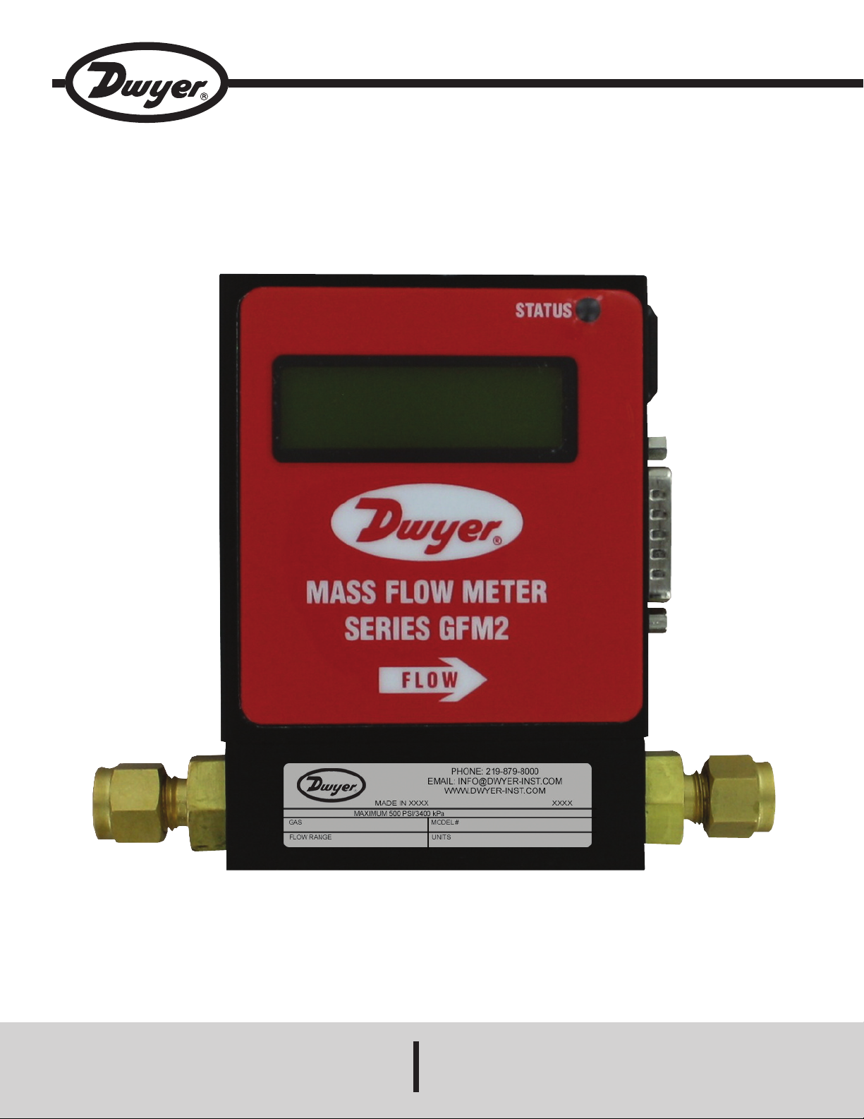
Series GFM2 Digital Mass Flow Meter
Installation and Operating Instructions
Bulletin F-GFM2 Rev A
DWYER INSTRUMENTS, INC.
Phone: 219/879-8000 www.dwyer-inst.com
Page 2

TABLE OF CONTENTS
1. Unpacking the GFM2 Flow Meter . . . . . . . . . . . . . . . . . . . . . . . . . . . . . . . . . .3
1.1 Inspect Package for External Damage . . . . . . . . . . . . . . . . . . . . . . . . . . . .3
1.2 Unpack the Mass Flow Meter . . . . . . . . . . . . . . . . . . . . . . . . . . . . . . . . . . .3
1.3 Returning Merchandise for Repair . . . . . . . . . . . . . . . . . . . . . . . . . . . . . . .3
2. Installation . . . . . . . . . . . . . . . . . . . . . . . . . . . . . . . . . . . . . . . . . . . . . . . . . . . .3
2.1 Primary Gas Connections . . . . . . . . . . . . . . . . . . . . . . . . . . . . . . . . . . . . .3
2.2 Electrical Connections . . . . . . . . . . . . . . . . . . . . . . . . . . . . . . . . . . . . . . . .3
2.2.1 Power Supply Connections . . . . . . . . . . . . . . . . . . . . . . . . . . . . . . . .3
2.2.2 Output Signal Connections . . . . . . . . . . . . . . . . . . . . . . . . . . . . . . . .3
2.2.3 Output Communication Parameters and Connections . . . . . . . . . . .3
3. Principle of Operation . . . . . . . . . . . . . . . . . . . . . . . . . . . . . . . . . . . . . . . . . . .4
7. Calibration Procedures . . . . . . . . . . . . . . . . . . . . . . . . . . . . . . . . . . . . . . . . . .8
7.1 Flow Calibration . . . . . . . . . . . . . . . . . . . . . . . . . . . . . . . . . . . . . . . . . . . . .8
7.2 Gas Flow Calibration of GFM2 Mass Flow Meters . . . . . . . . . . . . . . . . . .8
7.2.1 Connections and Initial Warm Up . . . . . . . . . . . . . . . . . . . . . . . . . . .8
7.2.2 ZERO Check/Adjustment . . . . . . . . . . . . . . . . . . . . . . . . . . . . . . . . . .8
7.2.3 Gas Linearization Table Adjustment . . . . . . . . . . . . . . . . . . . . . . . . .8
7.3 Analog Output Calibration of GFM2 Mass Flow Meters . . . . . . . . . . . . . . .9
7.3.1 Initial Setup . . . . . . . . . . . . . . . . . . . . . . . . . . . . . . . . . . . . . . . . . . . .9
7.3.2 Gas Flow 0 to 5 VDC Analog Output Calibration . . . . . . . . . . . . . . . .9
7.3.3 Gas Flow 4 to 20 mA Analog Output Calibration . . . . . . . . . . . . . . . .9
8. RS-485/RS-232 Software Interface Commands . . . . . . . . . . . . . . . . . . . . . . .9
8.1 General . . . . . . . . . . . . . . . . . . . . . . . . . . . . . . . . . . . . . . . . . . . . . . . . . . . .9
8.2 Commands Structure . . . . . . . . . . . . . . . . . . . . . . . . . . . . . . . . . . . . . . . . .9
8.3 ASCII Commands Set . . . . . . . . . . . . . . . . . . . . . . . . . . . . . . . . . . . . . . .10
4. Specifications . . . . . . . . . . . . . . . . . . . . . . . . . . . . . . . . . . . . . . . . . . . . . . . . . .4
5. Operating Instructions . . . . . . . . . . . . . . . . . . . . . . . . . . . . . . . . . . . . . . . . . . .5
5.1 Preparation and Warm Up . . . . . . . . . . . . . . . . . . . . . . . . . . . . . . . . . . . . .5
5.2 Swamping Condition . . . . . . . . . . . . . . . . . . . . . . . . . . . . . . . . . . . . . . . . . .5
5.3 GFM2 Parameters Settings . . . . . . . . . . . . . . . . . . . . . . . . . . . . . . . . . . . .5
5.3.1 Engineering Units Settings . . . . . . . . . . . . . . . . . . . . . . . . . . . . . . . . .5
5.3.2 Gas Table Settings . . . . . . . . . . . . . . . . . . . . . . . . . . . . . . . . . . . . . . .6
5.3.3 Totalizer Settings . . . . . . . . . . . . . . . . . . . . . . . . . . . . . . . . . . . . . . . .6
5.3.4 Flow Alarm Settings . . . . . . . . . . . . . . . . . . . . . . . . . . . . . . . . . . . . . .6
5.3.5 Relay Assignment Settings . . . . . . . . . . . . . . . . . . . . . . . . . . . . . . . .6
5.3.6 K-Factors Settings . . . . . . . . . . . . . . . . . . . . . . . . . . . . . . . . . . . . . . .6
5.3.7 Zero Calibration . . . . . . . . . . . . . . . . . . . . . . . . . . . . . . . . . . . . . . . . .6
5.3.8 Self Diagnostic Alarm . . . . . . . . . . . . . . . . . . . . . . . . . . . . . . . . . . . . .7
5.4 Analog Output Signals Configuration . . . . . . . . . . . . . . . . . . . . . . . . . . . . .7
6. Maintenance . . . . . . . . . . . . . . . . . . . . . . . . . . . . . . . . . . . . . . . . . . . . . . . . . . .7
6.1 Introduction . . . . . . . . . . . . . . . . . . . . . . . . . . . . . . . . . . . . . . . . . . . . . . . . .7
6.2 Flow Path Cleaning . . . . . . . . . . . . . . . . . . . . . . . . . . . . . . . . . . . . . . . . . .7
6.2.1 Restrictor Flow Element (RFE) . . . . . . . . . . . . . . . . . . . . . . . . . . . . .7
6.2.2 GFM2 Models . . . . . . . . . . . . . . . . . . . . . . . . . . . . . . . . . . . . . . . . . .7
9. Troubleshooting . . . . . . . . . . . . . . . . . . . . . . . . . . . . . . . . . . . . . . . . . . . . . . .10
9.1 Common Conditions . . . . . . . . . . . . . . . . . . . . . . . . . . . . . . . . . . . . . . . . .10
9.2 Troubleshooting Guide . . . . . . . . . . . . . . . . . . . . . . . . . . . . . . . . . . . . . . .12
9.3 Technical Assistance . . . . . . . . . . . . . . . . . . . . . . . . . . . . . . . . . . . . . . . .13
10. Calibration Conversions from Reference Gases . . . . . . . . . . . . . . . . . . .13
Appendix I GFM2 EEPROM Variables . . . . . . . . . . . . . . . . . . . . . . . . . . . .14
Appendix II Internal User Selectable Gas Factor Table
(Internal “K” Factors) . . . . . . . . . . . . . . . . . . . . . . . . . . . . . . .15
Appendix III Gas Factor Table (“K” Factors) . . . . . . . . . . . . . . . . . . . . . .16
Appendix IV Component Diagram . . . . . . . . . . . . . . . . . . . . . . . . . . . . . . .18
Appendix V Dimensional Drawings . . . . . . . . . . . . . . . . . . . . . . . . . . . . .19
Appendix VI Maintenance/Repair, Warranty/Return . . . . . . . . . . . . . . . . .19
Page 2
Page 3

1. UNPACKING THE GFM2 MASS FLOW METER
1.1 - Inspect Package for External Damage
Your GFM2 Mass Flow Meter was carefully packed in a sturdy cardboard carton,
with anti-static cushioning materials to withstand shipping shock. Upon receipt,
inspect the package for possible external damage. In case of external damage to
the package contact the shipping company immediately.
1.2 - Unpack the Mass Flow Meter
Open the carton carefully from the top and inspect for any sign of concealed
shipping damage. In addition to contacting the shipping carrier please forward a
copy of any damage report to your distributor or Dwyer Instruments, Inc directly.
When unpacking the instrument please make sure that you have all the items
indicated on the Packing List. Please report any shortages promptly.
1.3 - Maintenance/Repair
Upon final installation of the Series GFM2, no routine maintenance is required. The
Series GFM2 is not field serviceable and should be returned if repair is needed.
Field repair should not be attempted and may void warranty.
Warranty/Return
Refer to “Terms and Conditions of Sales” in our catalog and on our website. Contact
customer service to receive a Return Goods Authorization number before shipping
the product back for repair. Be sure to include a brief description of the problem
plus any additional application notes.
2. INSTALLATION
2.1 - Primary Gas Connections
Please note that the GFM2 Mass Flow Meter will not operate with liquids. Only
clean gases are allowed to be introduced into the instrument. If gases are
contaminated they must be filtered to prevent the introduction of impediments into
the sensor.
CAUTION
application. For more information, contact your distributor or Dwyer.
Attitude limit of Mass Flow Meter is ±15° from calibration position (standard
calibration is in horizontal position). This means that the gas flow path of the Flow
Meter must be within this limit in order to maintain the original calibration accuracy.
Should there be need for a different orientation of the meter, re-calibration may be
necessary. It is also preferable to install the GFM2 transducer in a stable
environment, free of frequent and sudden temperature changes, high moisture, and
drafts.
Prior to connecting gas lines inspect all parts of the piping system including ferrules
and fittings for dust or other contaminants. Be sure to observe the direction of gas
flow as indicated by the arrow on the front of the meter when connecting the gas
system to be monitored. Insert tubing into the compression fittings until the ends of
the properly sized tubing home flush against the shoulders of the fittings.
Compression fittings are to be tightened according to the manufacturer's
instructions to one and one quarter turns. Avoid over tightening which will seriously
damage the Restrictor Flow Elements (RFE's)!
WARNING
pressure above 500 PSIA (34.47 bars) will seriously damage the flow sensor and
may cause serious injury or death.
GFM2 transducers are supplied with standard 1/4˝ or 3/8˝ inlet and outlet
compression fittings which should not be removed unless the meter is being
cleaned or calibrated for a new flow range.
GFM2 transducers should not be used for monitoring OXYGEN
gas unless specifically cleaned and prepared for such
For models GFM2 models the maximum pressure in the gas
line should not exceed 500 PSIA (34.47 bars). Applying
CAUTION
2.2.2 - Output Signals Connections
CAUTION
do so might cause damage to this device. Be sure to check that the wiring and
the polarity of the power supply is correct before turning the power ON. Wiring
error may cause damage or faulty operation.
GFM2 Mass Flow Meters are equipped with either calibrated 0 to 5 VDC (0 to 10
VDC optional) or calibrated 4 to 20 mA output signals (jumper selectable). This
linear output signal represents 0 to 100% of the flow meter's full scale range.
CAUTION
output signals!
Flow 0 to 5 VDC or 4 to 20 mA output signal connection:
Plus (+) ------------------- pin 2 of the 15 pin "D" connector
Minus (-) ------------------- pin 1 of the 15 pin "D" connector
To eliminate the possibility of noise interference, use a separate cable entry for the
DC power and signal lines.
2.2.3 - Communication Parameters and Connections
The digital interface operates via RS-485 (optional RS-232 or Profibus DP is
available) and provides access to applicable internal data including: flow, CPU
temperature, pressure reading, auto zero, totalizer and alarm settings, gas table,
conversion factors and engineering units selection, dynamic response
compensation and linearization table adjustment.
Communication Settings:
RS-485 Communication Interface Connection:
The RS-485 converter/adapter has to be configured for: multidrop, 2 wire, half
duplex mode. Settings for the receiver circuit usually should follow the selection
made for the transmitter circuit in order to eliminate echo.
RS-485 T(-) or R(-) -------- pin 8 of the 15 pin "D" connector (TX-)
RS-485 T(+) or R(+) -------- pin 15 of the 15 pin "D" connector (RX+)
RS-485 GND (if available) -------- pin 9 of the 15 pin "D" connector (GND)
RS-232 Communication Interface Connection:
Crossover connection has to be established:
RS-232 RX
(pin 2 on the DB9 connector) -------- pin 8 of the 15 pin "D" connector (TX)
RS-232 TX
(pin 3 on the DB9 connector) -------- pin 15 of the 15 pin "D" connector (RX)
RS-232 GND
(pin 5 on the DB9 connector) -------- pin 9 of the 15 pin "D" connector (GND)
Do not apply power voltage above 26 VDC. Doing so will cause
GFM2 damage or faulty operation.
When connecting the load to the output terminals, do not
exceed the rated values shown in the specifications. Failure to
All 4 to 20 mA current loop outputs are self-powered (nonisolated). Do not connect an external voltage source to the
Baud rate: -------- 9600 baud
Stop bit: -------- 1
Data bits: -------- 8
Parity: -------- None
Flow Control: -------- None
Using a Helium Leak Detector or other equivalent method perform a thorough
leak test of the entire system. (All GFM2’s are checked prior to shipment for
leakage within stated limits. See specifications in this manual.)
2.2 - Electrical Connections
GFM2 is supplied with a 25 pin "D" connector. Pin diagram is presented in figure
b-1.
2.2.1 - Power Supply Connections
The power supply requirements for GFM2 transduers are: 11 to 26 VDC, (unipolar
power supply)
DC Power (+) --------------- pin 7 of the 15 pin "D" connector
DC Power (-) --------------- pin 5 of the 15 pin "D" connector
Page 3
Page 4
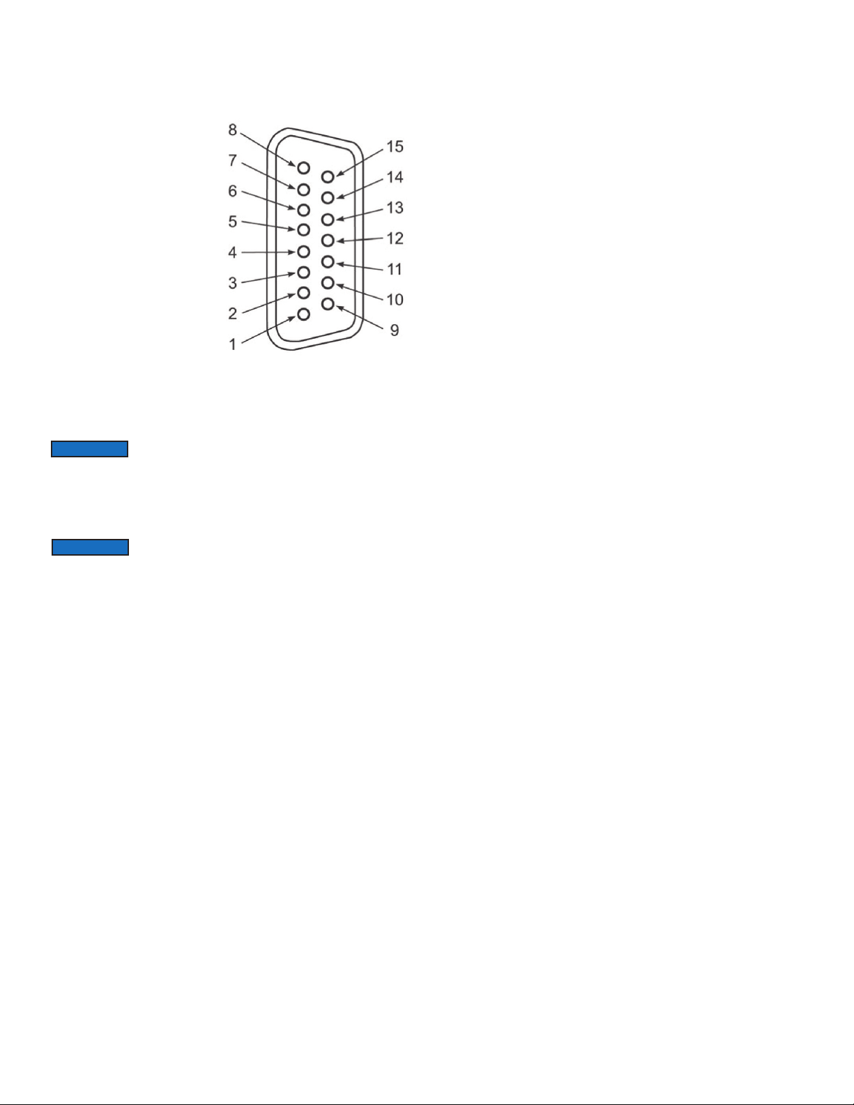
PIN GFM2 FUNCTION
1 Common, Signal Ground
For Pin 2 (4 to 20 mA return)
2 0 to 5 VDC or 4 to 20 mA
Flow Signal Output
3 Relay No. 2 - Normally Open
Contact
4 Relay No. 2 - Common
Contact
5 Common, Power Supply
(- DC power for 11 to 26 VDC)
6 Relay No. 1 - Common
Contact
7 Plus Power Supply
(+ DC power for 11 to 26 Vdc)
8 RS485 (-) (Optional RS232 TX)
9 RS232 Signal GND (RS-485
GND Optional)
10 Do not connect
(Test/Maintenance terminal)
11 Relay No. 2 - Normally Closed
Contact
12 Relay No. 1 - Normally Open
Contact
13 Relay No. 1 - Normally Closed
Contact
14 Do not connect
(Test/Maintenance terminal)
15 RS485 (+) (Optional RS232
RX) Shield Chassis Ground
NOTICE
nonconforming patterns and the numbering sequence on your mating
connector may or may not coincide with the numbering sequence shown in our
pin configuration table above. It is imperative that you match the appropriate wires
in accordance with the correct sequence regardless of then particular numbers
displayed on the mating connector.
NOTICE
In general, "D" Connector numbering patterns are
standardized. There are, however, some connectors with
Make sure power is OFF when connecting or disconnecting
any cables in the system.
Additionally, the GFM2 Mass Flow Meter incorporates a precision analog
microcontroller and non-volatile memory that stores all hardware specific variables
and up to 10 different calibration tables. The flow rate can be displayed in 23
different volumetric or mass flow engineering units. Flow meter parameters and
functions can be programmed remotely via the RS-232/RS-485 interface or
optional Profibus DP interface. GFM2 flow meters support various functions
including: programmable flow totalizer, low, high or range flow alarm, automatic
zero adjustment (activated via local button or communication interface), 2
programmable SPDT relays output, 0 to 5 VDC / 4 to 20 mA analog outputs (jumper
selectable), self diagnostic alarm, 36 internal and user defined K-factor. Optional
local 2x16 LCD readout with adjustable back light provides flow rate and total
volume reading in currently selected engineering units and diagnostic events
indication.
SPECIFICATIONS
Service: Clean gases compatible with wetted parts.
Wetted Materials:
GFM2-X-X-A: Anodized aluminum, brass, 316 SS fluoroelastomer O-rings;
GFM2-X-X-S: 316 SS, and fluoroelastomer O-rings; Buna-N, EPR and PTFE
O-rings optional.
Accuracy: ±1% FS.
Repeatability: ±0.25% FS.
Response Time: 2 seconds to within ±2% of actual flow.
Output Signal: Linear 0 to 5 VDC (3000 Ω min. load impedance) and 4 to 20 mA
(500 Ω max. loop resistance).
Max. Particulate Size: 5 microns.
Temperature Limits: 32 to 122°F (0 to 50°C).
Power Supply: 11 to 26 VDC.
Process Connections: 1/8˝ compression fitting for flow rates ≤ 10 L/min; 1/4˝ for ≤
50 L/min; 3/8˝ for ≤ 100 L/min.
Display: 2 x 16 character LCD.
Pressure Limits: 500 psig (34.5 bar).
Leak Integrity: 1 x 10⁻⁹ smL/sec of helium.
Weight: 1.05 lb (0.48 kg).
The (+) and (-) power inputs are each protected by a 300 mA M (medium time-lag)
resettable fuse. If a shorting condition or polarity reversal occurs, the fuse will cut
power to the flow transducer circuit. Disconnect the power to the unit, remove the
faulty condition, and reconnect the power. The fuse will reset once the faulty
condition has been removed. DC Power cable length may not exceed 9.5 feet (3
meters).
Use of the GFM2 flow transducer in a manner other than that specified in this
manual or in writing from Dwyer, may impair the protection provided by the
equipment.
3. Principle of Operation
The stream of gas entering the Mass Flow transducer is split by shunting a small
portion of the flow through a capillary stainless steel sensor tube. The remainder of
the gas flows through the primary flow conduit. The geometry of the primary conduit
and the sensor tube are designed to ensure laminar flow in each branch.
According to principles of fluid dynamics the flow rates of a gas in the two laminar
flow conduits are proportional to one another. Therefore, the flow rates measured
in the sensor tube are directly proportional to the total flow through the transducer.
In order to sense the flow in the sensor tube, heat flux is introduced at two sections
of the sensor tube by means of precision wound heater-sensor coils. Heat is
transferred through the thin wall of the sensor tube to the gas flowing inside. As
gas flow takes place heat is carried by the gas stream from the upstream coil to
the downstream coil windings. The resultant temperature dependent resistance
differential is detected by the electronic control circuit. The measured temperature
gradient at the sensor windings is linearly proportional to the instantaneous rate
of flow taking place.
An output signal is generated that is a function of the amount of heat carried by
the gases to indicate mass-molecular based flow rates.
Page 4
Page 5
low Rates
F
Flow rates are stated for Nitrogen at STP conditions [i.e. 70°F (21.1°C) at 1 atm].
For other gases use the K factor as a multiplier from APPENDIX III.
Model
std liters/min)
(
GFM2-X-101
Flow Rate
odel
M
FM2-X-101 Transmitter
G
T
. OPERATING INSTRUCTIONS
5
.1 - Preparation and Warm Up
5
p to 10
u
able IV - Pressure Drops
aximum Pressure Drop
M
mm H
(
30
1
eight
W
.20 lb (1.00 kg)
2
)
0
(psid)
2
.18
0
hipping Weight
S
.70 lb (1.68 kg)
3
(kPa)
.275
1
It is assumed that the Digital Mass Flow Meter has been correctly installed and
thoroughly leak tested as described in section 2. Make sure the flow source is OFF.
When applying power to a flow meter within the first 2 seconds you will see on the
CD display: the product name, the software version, and revision of the
L
EPROM table (applicable for LCD option only).
E
S: Ver1.4 Rev.A0
Figure b-2: GFM2 First Banner Screen
OTICE
N
or the GFM2 transducer with LCD option: If the LCD diagnostic is activated, the
F
econd line of the LCD will display the time remaining until the end of the warm
s
p period (Minutes:Seconds format) and will alternatively switch to Totalizer reading
u
ndication every 2 seconds.
i
uring the first 6 minutes of the initial powering of the GFM2
D
ransducer, the status LED will emit a constant amber light.
t
F: 50.0 L/min
** WarmUp 2:39 **
Figure b-5: GFM2 Main Screen During Sensor Warm Up Period.
NOTICE
peration, ready to measure). For GFM2 with LCD option, the screen will reflect
o
flow and totalizer reading. (see Figure b-4).
5.2 Swamping Condition
If a flow of more than 10% above the maximum flow rate of the Mass Flow Meter
s taking place, a condition known as "swamping" may occur. Readings of a
i
swamped" meter cannot be assumed to be either accurate or linear. Flow must
"
e restored to below 110% of maximum meter range. Once flow rates are lowered
b
to within calibrated range, the swamping condition will end. Operation of the meter
above 110% of maximum calibrated flow may increase recovery time.
fter 6 minutes of the initial powering of the GFM2 transducer,
A
he status LED will emit a constant GREEN light (normal
t
Within the next 2 seconds, the RS-485 network address, the analog output settings,
nd currently selected gas calibration table will be displayed (applicable for LCD
a
ption only).
o
Ad: 11 Out: 0 to 5 VDC
Gas# 1 AIR
Figure b-3: GFM2 Second Banner Screen
NOTICE
Actual content of the LCD screen may vary depending on the
model and device configuration.
After 2 seconds, the LSD display switches to the main screen with the following
information:
- Mass Flow reading in current engineering units (upper line).
- Totalizer Volume reading in current volume or mass based engineering units
(lower line).
F: 50.0 L/min
T: 75660.5 Ltr
Figure b-4: GFM2 Main Screen
NOTICE
During initial powering of the GFM2 transducer, the flow output signal will be
indicating a higher than usual output. This is an indication that the GFM2
transducer has not yet attained its minimum operating temperature. This condition
will automatically cancel within a few minutes and the transducer should eventually
indicate 0.
Allow the Digital Mass Flow Meter to warm-up for a MINIMUM
of 6 minutes.
5.3 GFM2 Parameters Settings
.3.1 Engineering Units Settings
5
he GFM2 Mass Flow Meter is capable of displaying flow rate with 23 different
T
Engineering Units. Digital interface commands (8.3 ASCII Command Set “GFM2
SOFTWARE INTERFACE COMMANDS”) are provided to:
- get currently active Engineering Units
- set desired Engineering Units.
The following Engineering Units are available:
Units of Measure
Number
1
2
3
4
5
6
7
8
9
10
11
12
13
14
15
16
17
18
19
20
21
22
23
Index
0
1
2
3
4
5
6
7
8
9
10
11
12
13
14
15
16
17
18
19
20
21
22
Flow Rate
Engineering
Units
%
mL/sec
mL/min
mL/hr
L/sec
L/min
L/hr
3
m
/sec
3
m
/min
3
m
/hr
3
ft
/sec
3
ft
/min
3
ft
/hr
g/sec
g/min
g/hr
kg/sec
kg/min
kg/hr
Lb/sec
Lb/min
Lb/hr
User
Totalizer
Engineering
Units
%s
mL
mL
mL
Ltr
Ltr
Ltr
3
m
3
m
3
m
3
ft
3
ft
3
ft
g
g
g
kg
kg
kg
Lb
Lb
Lb
UD
Description
Percent of full scale
Mililiter per second
Mililiter per minute
Mililiter per hour
Liter per second
Liter per minute
Liter per hour
Cubic meter per second
Cubic meter per minute
Cubic meter per hour
Cubic feet per second
Cubic feet per minute
Cubic feet per hour
Grams per second
Grams per minute
Grams per hour
Kilograms per second
Kilograms per minute
Kilograms per hour
Pounds per second
Pounds per minute
Pounds per hour
User Defined
Page 5
NOTICE
automatically.
Once Flow Unit of Measure is changed, the Totalizer’s
Volume/Mass based Unit of Measure will be changed
Page 6
5.3.2 Gas Table Settings
The GFM2 Mass Flow Meter is capable of storing calibration data for up to 10
different gases. Digital interface commands are provided to:
- get currently active Gas Table number and Gas name
- set desired Gas Table.
NOTICE
ordered). If instead of the valid Gas name (for example NITROGEN), the LCD
screen or digital interface displays Gas designator as “Uncalibrated”, then the
user has chosen the Gas Table which was not calibrated. Using an “Uncalibrated”
Gas Table will result in erroneous reading.
5.3.3 Totalizer Settings
The total volume of the gas is calculated by integrating the actual gas flow rate
with respect to the time. Digital interface commands are provided to:
- reset the totalizer to ZERO
- start the totalizer at a preset flow
- assign action at a preset total volume
- start/stop (enable/disable) totalizing the flow
- read totalizer via digital interface
The Totalizer has several attributes which may be configured by the user. These
attributes control the conditions which cause the Totalizer to start integrating the gas
flow and also to specify actions to be taken when the Total Volume is outside the
specified limit.
NOTICE
entered in % FS engineering unit. The Totalizer will not totalize until the flow rate
becomes equal to or more than the Totalizer Start value. Totalizer Stop values
must be entered in currently active volume / mass based engineering units. If the
Totalizer Stop at preset total volume feature is not required, then set Totalizer
Stop value to 0.
Totalizer action conditions become true when the totalizer reading and preset
"Stop at Total" volumes are equal.
By default the GFM2 is shipped with at least one valid
calibration table (unless optional additional calibrations were
Before enabling the Totalizer, ensure that all totalizer settings
are configured properly. Totalizer Start values have to be
Latch Mode - Controls Latch feature when Relays are assigned to Alarm event.
Following settings are available:
0 - Latch feature is disabled for both relays
1 - Latch feature is enabled for Relay#1 and disabled for Relay#2
2 - Latch feature is enabled for Relay#2 and disabled for Relay#1
3 - Latch feature is enabled for both relays.
NOTICE
NOTICE
conditions. If Relay is assigned to the Alarm event, in some cases, the Alarm
Latch feature may be desirable.
The current Flow Alarm settings and status are available via digital interface (8.3
ASCII Command Set “GFM2 SOFTWARE INTERFACE COMMANDS”).
5.3.5 Relay Assignment Settings
Two sets of dry contact relay outputs are provided to actuate user supplied
equipment. These are programmable via digital interface such that the relays can
be made to switch when a specified event occurs (e.g. when a low or high flow
alarm limit is exceeded or when the totalizer reaches a specified value).
The user can configure each Relay action from 6 different options:
No Action : (N) No assignment (relay is not assigned to any events and not
energized).
Totalizer > Limit : (T) Totalizer reached preset limit volume.
High Flow Alarm : (H) High Flow Alarm condition.
Low Flow Alarm : (L) Low Flow Alarm condition.
Range between H&L : (R) Range between High and Low Flow Alarm condition.
Manual Enabled : (M) Activated regardless of the Alarm and Totalizer conditions.
5.3.6 K-Factors Settings
Conversion factors relative to nitrogen for up to 36 gases are stored in the GFM2
(see APPENDIX II). In addition, provision is made for a user-defined conversion
factor. Conversion factors may be applied to any of the ten gas calibrations via
digital interface commands.
If the alarm condition is detected, and the Relay is assigned to
Alarm event, the corresponding Relay will be energized.
By default, flow alarm is non-latching. That means the alarm is
indicated only while the monitored value exceeds the specified
Local maintenance push button is available for manual Totalizer reset on the field.
The maintenance push button is located on the right side of the flow meter inside
the maintenance window above the 15 pin D-connector (see Figure C-1 “GFM2
configuration jumpers”).
NOTICE
sequence is recommended:
1. Disconnect GFM2 from the power.
2. Press maintenance push button (do not release).
3. Apply power to the GFM2 while holding down the maintenance push button.
4. Release maintenance push button after 6 seconds. For GFM2 with optional
LCD, when GFM2 Main Screen appears (see Figure b-4).
5.3.4 Flow Alarm Settings
GFM2 provides the user with a flexible alarm/warning system that monitors the Gas
Flow for conditions that fall outside configurable limits as well as visual feedback for
the user via the status LED and LCD (only for devices with LCD option) or via a
Relay contact closure.
The flow alarm has several attributes which may be configured by the user via a
digital interface. These attributes control the conditions which cause the alarm to
occur and to specify actions to be taken when the flow rate is outside the specified
conditions.
Mode Enable /Disable - Allows the user to Enable/Disable Flow Alarm.
Low Alarm - The value of the monitored Flow in % FS below which is considered an
alarm condition.
NOTICE
High Alarm - The value of the monitored Flow in % FS above which is considered
an alarm condition.
NOTICE
Action Delay - The time in seconds that the Flow rate value must remain above the
high limit or below the low limit before an alarm condition is indicated. Valid settings
are in the range of 0 to 3600 seconds.
In order to locally Reset Totalizer, the reset push button must
be pressed during power up sequence. The following
The value of the Low alarm must be less than the value of the
High Alarm.
The value of the High alarm must be more than the value of
the Low Alarm.
The available K Factor settings are:
• Disabled (K = 1).
• Internal Index The index [0-35] from internal K factor table (see APPENDIX II).
• User Defined User defined conversion factor.
NOTICE
5.3.7 Zero Calibration
The GFM2 includes an auto zero function that, when activated, automatically
adjusts the mass flow sensor to read zero. The initial zero adjustment for your
GFM2 was performed at the factory. It is not required to perform zero calibration
unless the device has zero reading offset with no flow conditions.
NOTICE
condition is established.
Shut off the flow of gas into the Digital Mass Flow Meter. To ensure that no seepage
or leak occurs into the meter, it is good practice to temporarily disconnect the gas
source. The Auto Zero may be initiated via digital communication interface or locally
by pressing the maintenance push button, which is located on the right side of the
flow meter inside the maintenance window above the 15 pin D-connector (see
Figure C-1 “GFM2 configuration jumpers”).
NOTICE
will prevent initiating Auto Zero function via the maintenance push button before
the 6 minutes sensor warm up period has elapsed.
To start Auto Zero locally, press the maintenance push button. The status LED will
flash not periodically with the RED light. On the GFM2 with optional LCD, the
following screen will appear:
The conversion factors will not be applied for % FS
engineering unit.
Before performing Zero Calibration, make sure the device is
powered up for at least 15 minutes and absolutely no flow
The same maintenance push button is used for Auto Zero
initiation and Totalizer reset. The internal diagnostic algorithm
AUTOZERO IS ON!
Figure b-6: GFM2 Screen in the Beginning of Auto Zero Procedure
Page 6
Page 7
he Auto Zero procedure normally takes 1 to 2 minutes during which time the DP
T
Zero counts and the Sensor reading changes approximately every 3 to 6 seconds.
AUTOZERO IS ON!
S: 405 DP: 512
igure b-7: GFM2 During the Auto Zero Procedure
F
he nominal value for a fully balanced sensor is 120 counts. If the GFM2’s digital
T
signal processor was able to adjust the Sensor reading within 120 ± 10 counts,
then Auto Zero is considered successful. The status LED will return to a constant
GREEN light.
OTICE
N
If the device was unable to adjust the Sensor reading to within 120 ± 10 counts,
then Auto Zero is considered as unsuccessful. The constant RED light will appear
on the status LED. The user will be prompted with the “AutoZero ERROR!” screen.
NOTICE
5.3.8 Self Diagnostic Alarm
GFM2 series Mass Flow Meters are equipped with a self-diagnostic alarm which is
available via multicolor LED, digital interface and on screen indication (for devices
with optional LCD). The following diagnostic events are supported:
Number
1
2
3
4
5
6
7
8
9
10
NOTICE
event with the highest priority level will be indicated on the status LED and
displayed on the LCD (if equipped). All diagnostic events may be accessed
simultaneously via digital communication interface.
5.4 Analog Output Signals Configuration
GFM2 series Mass Flow Meters are equipped with calibrated 0 to 5 VDC and 4 to
20 mA output signals. The set of the jumpers (J7A, J7B, J7C) located on the right
side of the flow meter, inside of the maintenance window above the 15 pin Dconnector (see Figure C-1 “GFM2 configuration jumpers”) are used to switch
between 0 to 5 VDC or 4 to 20 mA output signals (see Table VI). Analog output
signals of 0 to 5 VDC and 4 to 20 mA are attained at the appropriate pins of the 15pin "D" connector (see Figure b-1) on the side of the GFM2 transducer.
he actual value of the Sensor and DP counts will vary for
T
ach GFM2.
e
or GFM2 with RS-232 option all Auto Zero status info
F
available via digital communication interface.
ED Color
L
Diagnostic Alarm Description
Auto Zero procedure is running
FATAL ERROR (reset or maintenance
ervice is required for return in to the
s
normal operation)
CPU Temperature too high (Electronics
Overheating)
Sensor in the warm up stage (first 6
minutes after power up sequence,
normal operation, no critical diagnostic
events present)
Flow Sensor Temperature too low
Flow Sensor Temperature too high
Totalizer Reading hit preset limit
Low Flow Alarm conditions
High Flow Alarm conditions
Normal operation, no diagnostic events
[0] - Priority Level is highest (most important). When two or
more diagnostic events are present at the same time, the
and Pattern
Not periodically
flashing RED
Constant RED
Flashing RED/UMBER
Constant UMBER
Flashing UMBER/OFF
Flashing RED/OFF
Flashing
GREEN/UMBER
Flashing GREEN/OFF
Flashing GREEN/RED
Constant GREEN
riority
P
Level
0
1
2
3
4
5
6
7
8
9
to 20 mA
5-9
6-10
7-11
4
J7.A
J7.B
J7.C
1-5
2-6
3-7
nalog Signal Output
A
Flow Rate Output
umper Header J7
J
able VI - Analog Output Jumper Configuration
T
See APPENDIX IV for actual jumpers layout on the PCB.
OTICE
N
. MAINTENANCE
6
.1 Introduction
6
It is important that the Mass Flow Meter is only used with clean, filtered gases.
Liquids may not be metered. Since the RTD sensor consists, in part, of a small
capillary stainless steel tube, it is prone to occlusion due to impediments or gas
rystallization. Other flow passages are also easily obstructed.
c
herefore, great care must be exercised to avoid the introduction of any potential
T
flow impediment. To protect the instrument, a 50 micron (GFM2-X-010) filter is built
into the inlet of the flow transducer. The filter screen and the flow paths may require
occasional cleaning as described below. There is no other recommended
maintenance required. It is good practice, however, to keep the meter away from
ibration, hot or corrosive environments and excessive RF or magnetic interference.
v
f periodic calibrations are required, they should be performed by qualified
I
personnel and calibrating instruments, as described in section 7. It is recommended
that units are returned to Dwyer for repair service and calibration.
ARNING
W
OMPLETELY PURGED AND NEUTRALIZED OF TOXIC, BACTERIOLOGICALLY
C
NFECTED, CORROSIVE OR RADIOACTIVE CONTENTS..
I
6.2 Flow Path Cleaning
Before attempting any disassembly of the unit for cleaning, try inspecting the flow
paths by looking into the inlet and outlet ends of the meter for any debris that may
be clogging the flow through the meter. Remove debris as necessary. If the flow
path is clogged, proceed with steps below.
Do not attempt to disassemble the sensor. If blockage of the sensor tube is not
alleviated by flushing through with cleaning fluids, please return meter for servicing.
CAUTION
6.2.1 Restrictor Flow Element (RFE)
The Restrictor Flow Element (RFE) is a precision flow divider inside the transducer
which splits the inlet gas flow by a preset amount to the sensor and main flow paths.
The particular RFE used in a given Mass Flow Meter depends on the gas and flow
range of the instrument.
6.2.2 GFM2-X-010 Models
Unscrew the inlet compression fitting of meter. Note that the Restrictor Flow
Element (RFE) is connected to the inlet fitting. Carefully disassemble the RFE
from the inlet connection. The 50 micron filter screen will now become visible.
Push the screen out through the inlet fitting. Clean or replace each of the removed
parts as necessary. If alcohol is used for cleaning, allow time for drying.
Inspect the flow path inside the transducer for any visible signs of contaminant. If
necessary, flush the flow path through with alcohol. Thoroughly dry the flow paths
by flowing clean dry gas through.
Carefully re-install the RFE and inlet fitting avoiding any twisting and deforming to
the RFE. Be sure that no dust has collected on the O-ring seal.
NOTICE
CALIBRATION POINT BE CHECKED AFTER RE-INSTALLING THE INLET
FITTING.
Digital output (communication) is simultaneously available with
analog output.
TO PROTECT SERVICING PERSONNEL IT IS MANDATORY
THAT ANY INSTRUMENT BEING SERVICED IS
DISASSEMBLY MAY COMPROMISE CURRENT
CALIBRATION.
OVER TIGHTENING WILL DEFORM AND RENDER THE RFE
DEFECTIVE. IT IS ADVISABLE THAT AT LEAST ONE
to 5 VDC
0
J7.A
J7.B
J7.C
Page 7
Page 8

. CALIBRATION PROCEDURES
7
NOTICE
METER, AS DESCRIBED IN THIS SECTION, WILL VOID ANY CALIBRATION
WARRANTY APPLICABLE.
.1 Flow Calibration
7
Dwyer Instruments' Flow Calibration Laboratory offers professional calibration
support for Mass Flow Meters using precision calibrators under strictly controlled
conditions. Calibrations can also be performed at customers' site using available
tandards.
s
actory calibrations are performed using NIST traceable precision volumetric
F
alibrators incorporating liquid sealed frictionless actuators.
c
Generally, calibrations are performed using dry nitrogen gas. The calibration can
then be corrected to the appropriate gas desired based on relative correction [K]
actors shown in the gas factor table (see APPENDIX III). A reference gas, other
f
han nitrogen, may be used to better approximate the flow characteristics of certain
t
ases. This practice is recommended when a reference gas is found with
g
thermodynamic properties similar to the actual gas under consideration. The
appropriate relative correction factor should be recalculated (see section 9).
EMOVAL OF THE FACTORY INSTALLED CALIBRATION
R
SEALS AND/OR ANY ADJUSTMENTS MADE TO THE
.2.3 Gas Linearization Table Adjustment
7
NOTICE
device’s front label). There is no need to adjust the gas linearization table unless
linearity adjustment is needed, flow range has to be changed, or new additional
alibration is required. Any alteration of the gas linearization table will
c
OID calibration warranty supplied with instrument.
V
Gas flow calibration parameters are separately stored in the Gas Dependent
portion of the EEPROM memory for each of 10 calibration tables. See APPENDIX
for complete list of gas dependent variables.
I
NOTICE
be applied to the currently selected gas. Use Gas Select command via digital
communication interface or Dwyer supplied calibration and maintenance software
to verify current gas table or select a new gas table.
ctual flow values are entered in normalized fraction format: 100.000 % FS
A
orresponds to 1.000000 flow value and 0.000 % FS corresponds to 0.000000 flow
c
value. The valid range for flow values is from 0.000000 to 1.000000 (note: GFM2
will accept up to 6 digits after decimal point).
our GFM2 Digital Mass Flow Meter was calibrated at the
Y
factory for the specified gas and full scale flow range (see
ake sure the correct gas number and name selected are
M
urrent. All adjustments made to the gas linearization table will
c
It is standard practice to calibrate Mass Flow Meters with dry nitrogen gas at
0.0°F (21.1°C), 20 psia (137.9 kPa absolute) inlet pressure and 0 psig outlet
7
ressure. It is best to calibrate GFM2 transducers to actual operating conditions.
p
pecific gas calibrations of non-toxic and non-corrosive gases are available for
S
specific conditions. Please contact your distributor or Dwyer for a price quotation.
It is recommended that a flow calibrator be used which has at least four times better
collective accuracy than that of the Mass Flow Meter to be calibrated.
quipment required for calibration includes: a flow calibration standard, PC with
E
vailable RS-485/RS-232 communication interface, a certified high sensitivity
a
ulti meter (for analog output calibration only), an insulated (plastic) screwdriver,
m
a flow regulator (for example - metering needle valve) installed upstream from the
Mass Flow Meter, and a pressure regulated source of dry filtered nitrogen gas (or
other suitable reference gas). Using Dwyer supplied calibration and maintenance
software to simplify the calibration process is recommended.
Gas and ambient temperature, as well as inlet and outlet pressure conditions,
should be set up in accordance with actual operating conditions.
7.2 Gas Flow Calibration of GFM2 Mass Flow Meters
All adjustments in this section are made from the outside of the meter via digital
communication interface between a PC (terminal) and GFM2. There is no need to
disassemble any part of the instrument or perform internal PCB component
(potentiometers) adjustment.
GFM2 Mass Flow Meters may be field recalibrated/checked for the same range
they were originally factory calibrated for. When linearity adjustment is needed or
flow range changes are being made, proceed to step 7.2.3. Flow range changes
may require a different Restrictor Flow Element (RFE). Consult your distributor or
Dwyer for more information.
7.2.1 Connections and Initial Warm Up
Power up the Mass Flow Meter for at least 15 minutes prior to commencing the
calibration procedure. Establish digital RS-485/RS-232 communication between
PC (communication terminal) and the GFM2. Start Dwyer supplied calibration and
maintenance software on the PC.
7.2.2 ZERO Check/Adjustment
Using Dwyer supplied calibration and maintenance software open Back Door
access:
Sensor readings are entered in counts of 12 bits ADC output and should always
e in the range of 0 to 4095. There are 11 elements in the table so the data should
b
e obtained at an increment of 10.0 % of full scale (0.0, 10.0, 20.0, 30.0, 40.0, 50.0,
b
0.0, 70.0, 80.0, 90.0 and 100.0 % FS).
6
If a new gas table is going to be created, it is recommended to start calibration
from 100% FS. If only linearity adjustment is required, calibration can be
started in any intermediate portion of the gas table.
sing the flow regulator, adjust the flow rate to 100% of FS flow. Check the
U
low rate indicated against the flow calibrator. Observe the flow reading on the
f
GFM2. If the difference between calibrator and GFM2 flow reading is more than
0.5% FS, consult factory.
If the GFM2 flow reading is more than the calibrator reading, the number of counts
in the Index 133 must be decreased. If the GFM2 flow reading is less than the
calibrator reading, the number of counts in the Index 133 must be increased. Once
Index 133 is adjusted with a new value, check the GFM2 flow rate against the
calibrator and, if required, perform additional adjustments for Index 133.
If a simple communication terminal is used for communication with the GFM2, then
“MW” (Memory Write) command from the software interface commands set may
be used to adjust sensor value in the linearization table (see section 8.3 for
complete software interface commands list).
Memory Read “MR” command can be used to read the current value of the index.
Assuming the GFM2 is configured with RS-485 interface and has address “11”, the
following example will first read the existing value of Index 133 and then write a
new adjusted value:
!11,MR,133[CR] - reads EEPROM address 133
!11,MW,133,3450[CR] - writes new sensor value (3450 counts) in to the index 133
NOTICE
includes an automated calibration procedure which may radically simplify reading
and writing for the EEPROM linearization table.
Once 100% FS calibration is completed, the user can proceed with calibration for
another 9 points of the linearization table by using the same approach.
It is recommended to use Dwyer supplied calibration and
maintenance software for gas table calibration. This software
Query/BackDoor/Open
When software prompts with Warning, click the [YES] button. This will open the
access to the rest of the Query menu.
Start Sensor Compensated Average reading:
Query/Read/ SensorCompAverage
This will display Device Sensor Average ADC counts.
With no flow conditions, the sensor Average reading must be in the range 120±
10 counts. If it is not, perform Auto Zero procedure (see section 5.3.10 “Zero
Calibration”).
Page 8
Page 9
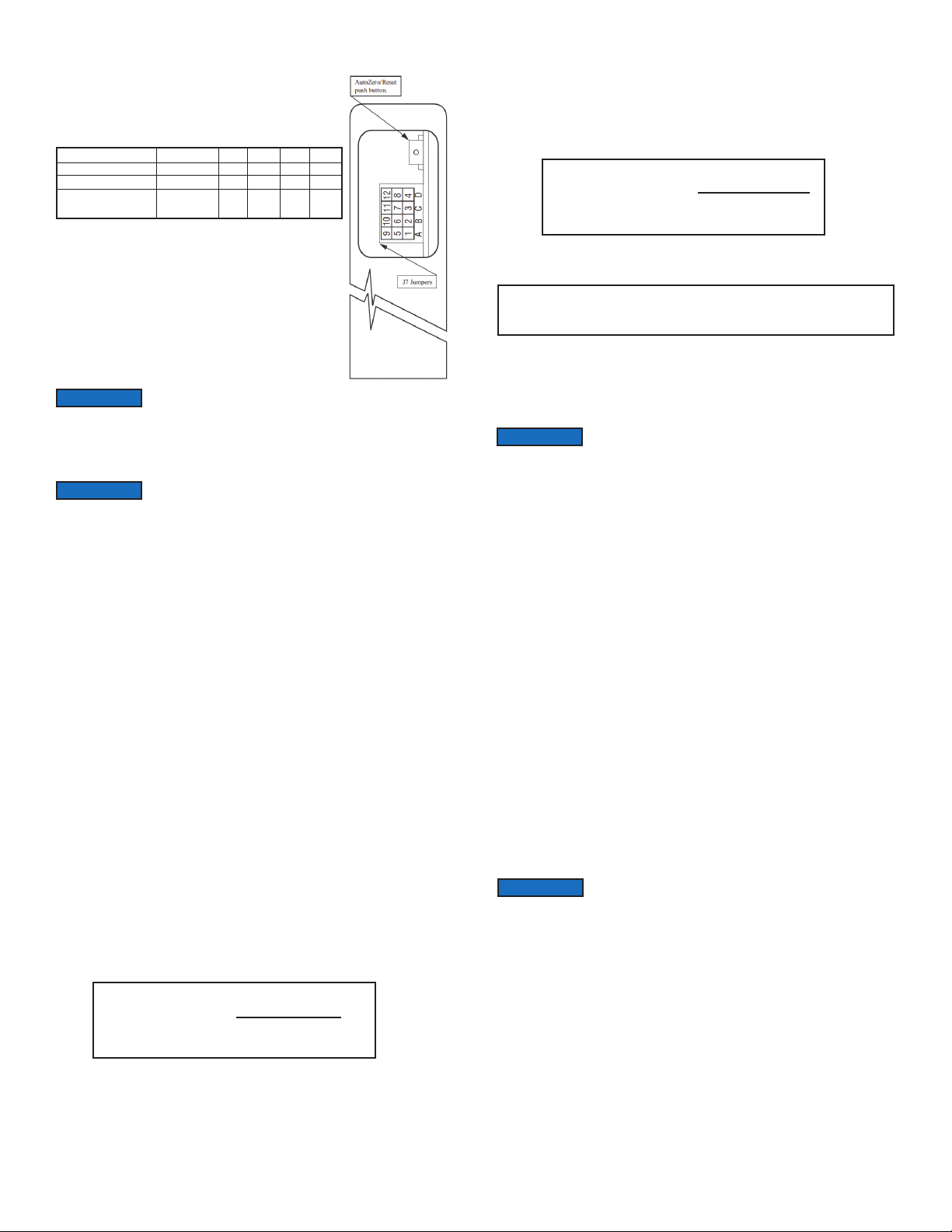
7.3 Analog output Calibration of GFM2 Mass Flow Meters
GFM2 series Mass Flow Meters are equipped with
calibrated 0 to 5 Vdc and 4 to 20 mA output signals. The set
of the jumpers (J7A, J7B, J7C) on the printed circuit board
is used to switch between 0 to 5 Vdc and 4 to 20 mA output
signals (Figure C-1 “GFM2 configuration jumpers).
Analog
Output
RS485
Terminal Resistor
Figure C-1 GFM2 Analog Output Configuration
The GFM2 analog output calibration involves calculation
and storing of the offset and span variables in the
EEPROM for each available output. The 0 to 5 VDC output
has only scale variable and 20 mA output has offset and
scale variables. The following is a list of the Gas
independent variables used for analog output computation:
Function
0 to 5 VDC
4 to 20 mA
OFF
Jumpers
ON
J7A
5-9
1-5
J7B
6-10
2-6
J7C
7-11
3-7
JCD
8-12
4-8
7.3.3 Gas Flow 4 to 20 mA Analog Output Calibration
1. Install jumpers J7A, J7B and J7C on the PC board for 4 to 20 mA output (see
Table VI).
2. Connect a certified high sensitivity multimeter set for the current measurement
to pins 2 (+) and 1 (-) of the 15 pins D connector.
3. Write 4000 counts to the DAC channel 1: !11,WRITE,1,4000[CR]
4. Read current with the meter and calculate:
AoutScale_mA =
5. Write zero counts to the DAC channel 1: !11,WRITE,1,0CR]
6. Read offset current with the meter and calculate:
4000
Reading[mA]
AoutOffset_mA = -FlowOutScale_mA*Offset_Reading[mA]
7. Save AoutScale_mA in to the EEPROM: !11,MW,27,Y[CR]
Save AoutOffset_mA in to the EEPROM: !11,MW,28,Z[CR]
NOTICE
full scale flow range (see the device’s front label). There is no need to perform
analog output calibration unless the EEPROM IC was replaced or offset/span
adjustment is needed. Any alteration of the analog output scaling variables in the
Gas independent table will VOID calibration warranty supplied with instrument.
NOTICE
software includes an automated calibration procedure which may radically
simplify calculation of the offsets and spans variables and, the reading and writing
for the EEPROM table.It is recommended to use the Dwyer supplied calibration
and maintenance software for analog output calibration. This software includes an
automated calibration procedure which may radically simplify calculation of the
offsets and spans variables and, the reading and writing for the EEPROM table.
Index Name Description
25 AoutScaleV - DAC 0 to 5 VDC Analog Output Scale
27 AoutScale_mA - DAC 4 to 20 mA Analog Output Scale
28 AoutOffset_mA - DAC 4 to 20 mA Analog Output Offset
7.3.1 Initial Setup
Power up the Mass Flow Meter for at least 15 minutes prior to commencing the
calibration procedure. Make sure absolutely no flow takes place through the
meter. Establish digital RS-485/RS-232 communication between PC
(communication terminal) and GFM2. The commands provided below assume that
calibration will be performed manually (w/o Dwyer supplied calibration and
maintenance software) and the device has RS-485 address 11. If Dwyer supplied
calibration and maintenance software is used, skip the next section and follow the
software prompts.
Enter Backdoor mode by typing: !11,MW,1000,1[CR]
Unit will respond with: !11,BackDoorEnabled: Y
Disable DAC update by typing: !11,WRITE,4,D[CR]
Unit will respond with: !11,DisableUpdate: D
The analog output available on the GFM2 Digital Mass Flow
Meter was calibrated at the factory for the specified gas and
It is recommended to use the Dwyer supplied calibration and
maintenance software for analog output calibration. This
Where: Y – the calculated AoutScale_mA value
Z – the calculated AoutOffset_mA value
NOTICE
command below).
Enable DAC update by typing: !11,WRITE,4,N[CR]
Unit will respond with: !11,DisableUpdate: N
Close BackDoor access by typing: !11,MW,1000,0[CR]
Unit will respond with: !11,BackDoorEnabled: N
8. RS-485/RS-232 SOFTWARE INTERFACE COMMANDS
8.1 General
The standard GFM2 comes with an RS-485 interface. For the optional RS-232
interface, the start character (!) and two hexadecimal characters for the address
must be omitted. The protocol described below allows for communications with
the unit using either a custom software program or a “dumb terminal.” All values
are sent as printable ASCII characters. For RS-485 interface, the start character
is always (!). The command string is terminated with a carriage return (line feeds
are automatically stripped out by the GFM2). See section 2.2.3 for information
regarding communication parameters and cable connections.
8.2 Commands Structure
The structure of the command string:
!<Addr>,<Cmd>,Arg1,Arg2,Arg3,Arg4<CR>
Where:
! Start character.
Addr RS485 device address in the ASCII representation of
Cmd The one or two character command from the table below.
Arg1 to Arg4 The command arguments from the table below.
CR Carriage Return character.
When done with the analog output calibration make sure the
DAC update is enabled and the BackDoor is closed (see
hexadecimal (00 through FF are valid).
Multiple arguments are comma delimited.
7.3.2 Gas Flow 0 to 5 VDC Analog Output Calibration
1. Install jumpers J7A, J7B and J7C on the PC board for 0-5 Vdc output (see
Table VI).
2. Connect a certified high sensitivity multi meter set for the voltage measurement
to the pins 2 (+) and 1 (-) of the 15 pins D connector.
3. Write 4000 counts to the DAC channel 1: !11,WRITE,1,4000[CR]
4. Read voltage with the meter and calculate:
AoutScaleV =
5. Save FlowOutScaleV in to the EEPROM: !11,MW,25,X[CR]
Where: X – the calculated AoutScaleV value.
20000
Reading[V]
NOTICE
RS-232 option.
Several examples of commands follow. All assume that the GFM2 has been
configured for address 18 (12 hex) on the RS485 bus:
1. To get current calibration tables: !12,G<CR>
2. To get current Alarm status: !12,A,R<CR>
3. To get a flow reading: !12,F<CR>
4. Set the high alarm limit to 85% of FS flow rate:
Page 9
Default address for all units is 11. Do not submit start
character and two character hexadecimal device address for
The GFM2 will reply: !12,G 0 AIR<CR>
(Assuming Current Gas table is #0, calibrated for AIR )
The GFM2 will reply: !12,N<CR>
(Assuming no alarm conditions)
The GFM2 will reply: !12,50.0<CR>
(Assuming the flow is at 50% FS)
The GFM2 will reply: !12,AH85.0<CR>
!12,A,H,85.0<CR>
Page 10

NOTICE
address is sent, all devices on the RS-485 bus execute the command but do not
reply with an acknowledge message.
he global address can be used to change RS-485 address for a particular
T
device with unknown address:
1. Make sure only one device (which address must be changed) is connected to
the RS-485 network.
. Type the memory write command with global address: !00,MW,7,XX[CR] where
2
X, the new hexadecimal address, can be [01 – FF].
X
.3 ASCII Commands Set
8
Command
Name
low
F
iagnostic
D
Roll Back
eature
N2F
Gas Select
Auto Zero
Flow Alarms
ddress 00 is reserved for global addressing. Do not assign,
A
the global address for any device. When command with global
No.
Description
equests the current flow sensor
R
eading in current EU.
r
nable / Disable LCD
E
Diagnostic messages (only
for LCD option).
Request current status of the
iagnostic events, LED status and
D
CD diagnostic mode
L
enabled/disabled).
(
Enable / Disable Roll back
o N
eature.
t
f
2
Selects one of the ten primary gas
calibration tables to use. Tables
are entered via the MEM
commands at time of calibration.
Starts /reads the status of the auto
zero feature (Note: The Z,N
command can be used only when
absolutely no flow thru the meter
and no earlier then 6 minutes after
power up. It can take several
minutes to complete. Unit will not
respond to other commands when
this is in progress).
Sets / reads the status of the gas
flow alarms.
Note: High and Low limits have to
be entered in the % FS. High
alarm value has to be more than
Low
alarm value.
Alarm conditions:
Flow > High Limit = H
Flow < Low Limit = L
Low < Flow < High = N
1
2
3
4
5
6
Command
F
D
N
G
Z
A
Argument 1
(enable LCD
E
Diagnostic
Messages)
D (disable LCD
Diagnostic
essages)
M
O ARGUMENT
N
read current status
(
of the diagnostic
word)
E
(enable Roll back to
N2)
D
enable Roll back to
(
N2)
NO ARGUMENT
(read current mode
of the N2Roll back )
0 (gas 0) to
9 (gas 9)
NO ARGUMENT
(read status)
N (do it now)
W (Write Zero to
EEPROM)
S (Status while auto
zero in progress)
V (Display zero
value)
H (high flow limit)
L (low flow limit)
A (action delay in
seconds)
E (enable alarm)
D (disable alarm)
R (read current
status)
S (read current
status)
B Block (Latch)
mode
fter assigning the new address, a device will accept commands with the new
A
address.
NOTICE
the same address are connected to the one RS-485 network, a communication
collision will take place on the bus and communication errors will occur.
Argument 2
<Value> (0 to
100%FS)
<Value> (0 to
100%FS)
<Value> (0 to
3600 sec)
<Value>
(0-disabled)
(1-enabl’d L)
(2-enabl’d H)
(3-both L,H)
o not assign the same RS-485 address for two or more
D
evices on the same RS-485 bus. If two or more devices with
d
Argument 3 Argument 4 Response
<Value> (Actual flow in
urrent engineering
c
nits)
u
:E
D
D:D
:0x0,L:9,E
D
x0 – diagnostic word
0
9 - current LED status
E - LCD mode (enabled)
N:E
:D
N
N:D or
N:E
G0 through G9,
<Gas Name>
G0 through G9,
<Gas Name>
ZN
ZW (when done)
ZNI,<value> while Z, N
is in progress
ZV, <zero value>
AH <Value>
AL <Value>
AA: <Value>
AE
AD
N - (no alarm)
H - (high alarm)
L - (low alarm)
AS:M,L,H,D,B where:
M – mode (E/D)
L – Low settings (%FS)
H – High settings (%FS)
D – Action Delay (sec)
B – Latch mode (0-3)
AB:<Value> where:
Value = 0 - 3
Page 10
Page 11
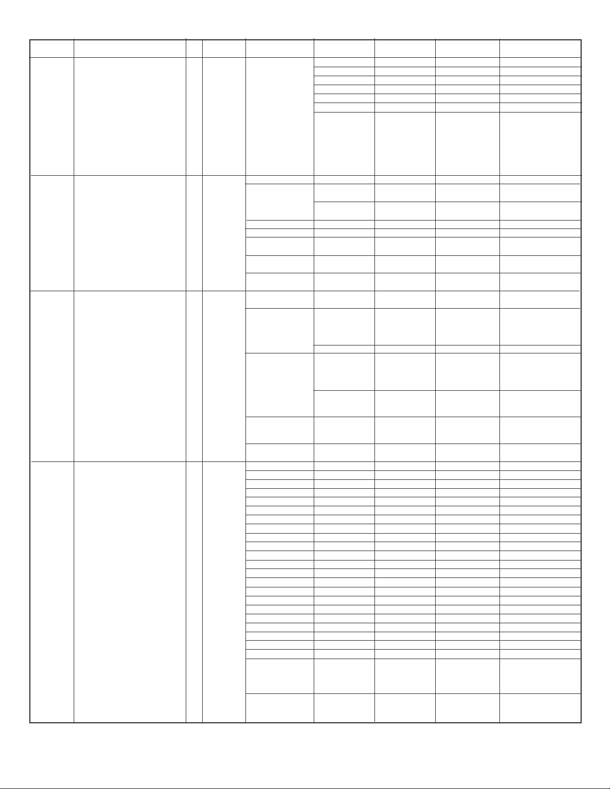
ommand
C
Name
Relay Action
Totalizer
K-Factors
Units
Description
Assigns action of the two SPDT
elays. The coil is energized
r
hen the condition specified by
w
n Argument 2 becomes true.
a
rgument 2:
A
N - no action, relay disabled
T - totalizer reading > limit
H - high flow alarm
- low flow alarm
L
- Range between High &
R
ow alarms
L
- Manual Relay overdrive
M
S - Read current status
Sets and controls action of the
flow totalizer.
OTE: If Warm Up Delay option
N
s set to E (enabled) the Totalizer
i
ill not totalize the flow during
w
first 6 minutes after power up.
Applies a gas correction factor to
the currently selected primary gas
calibration table.
NOTE: does not work with %FS
(
ngineering unit.)
e
ee list of the internal K-factors in
S
the operating manual.
Set the units of measure for gas
flow and totalizer reading.
Note: The units of the totalizer
output are not per unit time.
No.
7
8
9
10
Command
R
T
K
U
Argument 1
(relay 1)
1
(relay 2)
2
Z (reset to zero)
(start totalizer at
F
low FS)
f
(limit gas volume
L
n current EU)
i
D (disable totalizer)
E (enable totalizer)
R (read current
totalizer volume)
(warm up delay)
W
(setting status)
S
D (disable, sets
=1)
K
I (internal K-factor)
(user specified
U
actor)
f
S (status)
% (%FS)
mL/sec
mL/min
mL/hr
L/sec
L/min
L/hr
3
m
/sec
3
m
/min
3
m
/hr
3
f
/sec
3
f
/min
3
f
/hr
g/sec
g/min
g/hr
kg/sec
kg/min
kg/hr
Lb/sec
Lb/min
Lb/hr
USER (user
defined)
No Argument
<status> Returns
current EU
Argument 2
N
T
H
L
R
M
S
value> (flow
<
FS)
%
value> (gas
<
olume)
v
- enable
E
- disable
D
No argument
(enable
previously set
internal K-factor)
as Index (0-35)
G
o argument
N
enable
(
previously set
user K-factor)
<value> (decimal
correction factor)
(0-1000)
<value>
(conversion factor
from L/min)
Argument 3
S - seconds
M – minutes
H – hours (Time
base)
Argument 4
Y - use density
N – do not use
density
Response
1N or R2N
R
1T or R2T
R
1H or R2H
R
1L or R2L
R
R1R or R2R
R1M or R2M
RxN, RxT, RxH, RxL,
xR, RxM
R
TZ
F<value>
T
L<value>
T
TD
TE
<value>(in current EU)
W:E or TW:D
T
S: Mode, Start, Limit,
T
Warm Up
KD
KI,<value>,<Gas>
I,<Index>,<Gas>
K
U,<value>
K
KU,<value>
SK, <Mode>, <Index>,
<Value> where:
Mode: D, I, U
Index: 0-35
Value: K-Factor value
U:%
U:mL/sec
U:mL/min
U:mL/hr
U:L/sec
U:L/min
U:L/hr
3
U:m
/sec
3
U:m
/min
3
U:m
/hr
3
U:f
/sec
3
U:f
/min
3
U:f
/hr
U:g/sec
U:g/min
U:g/hr
U:kg/sec
U:kg/min
U:kg/hr
U:Lb/sec
U:Lb/min
U:Lb/hr
U:USER,<Factor>,
<Time base>,
<Density mode>
U,<EU name>
Page 11
Page 12

ommand
C
ame
N
aintenance
M
Timer
Full Scale
CD Back
L
ight
L
ead
R
EPROM
E
emory
M
rite
W
EEPROM
Memory
escription
D
ours since last time unit was
H
calibrated.
Returns the full scale rated flow in
/min. (Note: This term is not
L
ultiplied by the current K factor)
m
CD Back Light control
L
(0-100.0%)
0 - off
100 - Maximum Intensity
eads the value in the
R
pecified memory location.
s
Writes the specified value to the
specified memory location. Use
Carefully, can cause unit to
alfunction. (Note: Some
m
ddresses are write protected!)
a
o.
N
ommand
C
1
1
C
12
E
3
1
B
14
MR
5
1
W
M
rgument 1
A
(read timer)
R
(set timer to zero)
C
to 100%
0
o Argument
N
<current settings>
0000 to 999
Table Index)
(
000 to 999
0
Table Index)
(
rgument 2
A
alue
V
rgument 3 Argument 4 Response
A
Value> (in Hours)
<
C
C
<Value> (in L/min)
:<Counts>
B
here:
w
ounts (0 – 4095)
C
:<Value>
B
where:
Value (0 – 100.0)
<value>
W,XXX,<Value>
M
here:
w
XXX=Table Index
UART Error Codes:
1 - Not Supported Command or Back Door is not enabled.
- Wrong # of Arguments.
2
- Address is Out of Range (MR or MW commands).
3
- Wrong # of the characters in the Argument.
4
5 - Attempt to Alter Write Protected Area in the EEPROM.
6 - Proper Command or Argument is not found.
- Wrong value of the Argument.
7
8 - Reserved.
9 - Manufacture specific info EE KEY (wrong key or key is disabled).
9.2 Troubleshooting Guide
No.
Indication
1
No zero reading after 15 min. warm up time and
no flow condition.
2
Status LED indicator and LCD display remains
blank when unit is powered up. No response
when flow is introduced from analog outputs 0 to
5 VDC or 4 to 20 mA.
3
LCD display reading and/or analog output 0 to 5
VDC signal fluctuate in wide range during flow
measurement.
4
LCD display reading does correspond to the
correct flow range, but 0-5 Vdc output signal
does not change (always the same reading or
around zero).
5
LCD display reading and 0 to 5 Vdc output
voltage do correspond to the correct flow range,
but 4 to 20 mA output signal does not change
(always the same or reading around 4.0 mA).
6
Calibration is off (more than ±1.0% FS).
7
LCD display reading is above maximum flow
range and output volt age 0 to 5 VDC signal is
more than 5.0 VDC when gas flows through the
GFM2.
8
Gas flows through the GFM2, but LCD display
reading and the output voltage 0 to 5 Vdc signal
do not respond to flow.
Likely Reason
Embedded temperature has been
changed.
Power supply is bad or polarity is
reversed.
PC board is defective.
Output 0-5 Vdc signal (pins 2–1 of the Dconnector) is shorted on the GND or
overloaded.
Output 0 to 5 VDC schematic is burned
out or damaged.
Analog flow output scale and offset
variable are corrupted.
External loop is open or load resistance
more than 500 Ω.
Output 4 to 20 mA schematic is burned
out or damaged.
GFM2 has initial zero shift.
Sensor under swamping conditions (flow
is more than 10% above maximum flow
rate for particular GFM2).
PC board is defective.
The gas flow is too low for particular
model of GFM2.
GFM2 models: RFE is not connected
properly to the inlet fitting.
Sensor or PC board is defective.
9. TROUBLESHOOTING
9.1 Common Conditions
our GFM2 Digital Mass Flow Meter was thoroughly checked at numerous quality
Y
ontrol points during and after manufacturing and assembly operations. It was
c
alibrated according to your desired flow and pressure conditions for a given gas
c
or a mixture of gases.
t was carefully packed to prevent damage during shipment. Should you feel that
I
the instrument is not functioning properly, please check for the following common
conditions first:
Are all cables connected correctly? Are there any leaks in the installation? Is the
power supply correctly selected according to requirements? When several meters
re used a power supply with appropriate current rating should be selected.
a
Were the connector pinouts matched properly? When interchanging with other
manufacturers' equipment, cables and connectors must be carefully wired for
correct pin configurations. Is the pressure differential across the instrument
sufficient?
Solution
Perform Auto Zero Procedure (see section 5.3.6 “Zero
Calibration”).
Measure voltage on pins 7 and 5 of the 15 pin D-connector. If
voltage is out of specified range, then replace power supply with a
new one. If polarity is reversed (reading is negative) make correct
connection.
Return GFM2 to factory for repair.
Check external connections to pin 2 – 1, of the D-connector. Make
sure the load resistance is more than 1000 Ω.
Return GFM2 to factory for repair.
Restore original EEPROM scale and offset variable or perform
analog output recalibration (see section 7.3).
Check external connections to pins 2 and 15 of the D-connector.
Make sure the loop resistance is less than 500 Ω.
Return GFM2 to factory for repair.
Shut off the flow of gas into the GFM2 (ensure gas source is
disconnected and no seepage or leak occurs into the meter). Wait
for 15 min. with no flow condition and perform Auto Zero calibration
Procedure (see section 5.3.7 “Zero Calibration”).
Lower the flow through GFM2 within calibrated range or shut down
the flow completely. The swamping condition will end automatically.
Return GFM2 to factory for repair.
Check maximum flow range on transducer’s front panel and make
required flow adjustment.
Unscrew the inlet compression fitting of the meter and reinstall
RFE (see section 6.2.2). NOTE: Calibration accuracy can be
Return GFM2 to factory for repair.
Page 12
Page 13
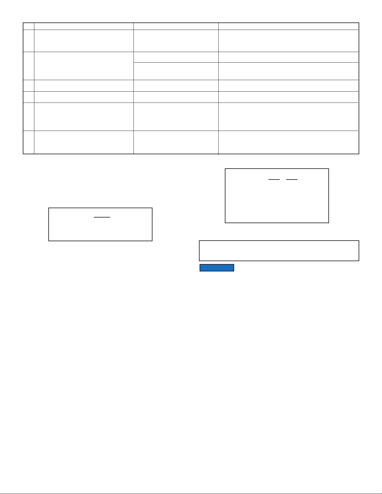
No.
Indication
9
Gas does not flow through the GFM2 with inlet
pressure applied to the inlet fitting. LCD display
reading and output voltage 0 to 5 VDC signal
show zero flow.
10
Gas flows through the GFM2, output voltage 0 to
5 VDC signal does not respond to flow (reading
near 1mV).
11
The Status LED indicator is rapidly flashing with
UMBER color on /off.
12
The Status LED indicator is rapidly flashing with
RED color on /off.
13
The Status LED indicator is rapidly flashing with
RED and UMBER colors.
14
The Status LED indicator is constantly on with
the RED light.
9.3 Technical Assistance
Dwyer Instruments will provide technical assistance over the phone to qualified
repair personnel. Please have your Serial Number and Model Number ready
when you call.
10. CALIBRATION CONVERSIONS FROM REFERENCE GASES
The calibration conversion incorporates the K factor. The K factor is derived from
gas density and coefficient of specific heat. For diatomic gases:
K
gas
where d = gas density (gram/liter)
Cp= coefficient of specific heat (cal/gram)
Note in the above relationship that d and Cp are usually chosen at the same
conditions (standard, normal or other).
1
=
d X C
p
Likely Reason
Filter screen obstructed at inlet.
Direction of the gas flow is reversed.
GFM2 is connected in the installation
with back pressure conditions and gas
leak exist in the system.
Sensor temperature is too low.
Sensor temperature is too high.
MCU temperature is too high (overload).
Fatal Error (EEPROM or Auto Zero
error).
Solution
Flush clean or disassemble to remove impediments or replace the
filter screen (see section 6.2). NOTE: Calibration accuracy can be
affected.
Check the direction of gas flow as indicated by the arrow on the front
of the meter and make required reconnection in the installation.
Locate and correct gas leak in the system. If GFM2 has internal leak
return it to factory for repair.
Make sure the ambient and gas temperatures are within specified
range (above 5°C).
Make sure the ambient and gas temperatures are within specified
range (below 50°C).
Disconnect power from the GFM2. Make sure the ambient
temperature is within specified range (below 50°C). Let the device
cool down for at least 15 min. Apply power to the GFM2 and check
Status LED indication. If overload condition will be indicated again the
unit has to be returned to the factory for repair.
Cycle the power on the GFM2. If Status LED still constantly on with
RED light, wait 6 min. and start Auto Zero function (see 5.3.7 Zero
Calibration). If after Zero Calibration the Fatal Error condition will be
indicated again the unit has to be returned to the factory for repair.
If the flow range of a Mass Flow Meter remains unchanged, a relative K factor is
used to relate the calibration of the actual gas to the reference gas.
Q
K
a
=
K
where Qa= mass flow rate of an actual gas
Qr= mass flow rate of a reference gas
Ka= K factor of an actual gas
Kr = K factor of a reference gas
For example, if we want to know the flow rate of oxygen and wish to calibrate
with nitrogen at 1000 SCCM, the flow rate of the oxygen is:
Q
= Q
O
where K = relative K factor to reference gas (oxygen to nitrogen)
NOTICE
computations will be performed internally by MCU.
= Q
a
2
If particular K factor is activated via digital interface, the user
does not need to perform any conversion. All conversion
Q
(sccm)
(sccm)
x K = 1000 X 0.9926 = 992.6 sccm
r
a
=
K
r
r
Page 13
Page 14

o.
N
ndication
I
0
lankEEPROM
B
1
SerialNumber
2
ModelNumber
3
SoftwareVer
4
imeSinceCalHr
T
5
ptions1
O
6
ackLight
B
7
ddressRS485
A
8
GasNumber
9
FlowUnits
0
1
AlarmMode
1
1
owAlarmPFS
L
2
1
iAlarmPFS
H
3
1
lmDelay
A
14
elaySetting
R
15
TotalMode
16
Total
7
1
TotalFlowStart
8
1
otalVolStop
T
9
1
factorMode
K
20
factorIndex
K
21
UserDefKfactor
22
UDUnitKfactor
23
UDUnitTimeBase
4
2
UDUnitDensity
5
2
outScaleV
A
6
2
RC_DP
D
27
outScale_mA
A
28
AoutOffset_mA
29
SensorZero
30
Klag [0]
1
3
Klag [1]
32
Klag [2]
33
Klag [3]
34
Klag [4]
35
Klag [5]
36
Kgain [0]
37
Kgain [1]
38
Kgain [2]
39
Kgain [3]
40
Kgain [4]
41
Kgain [5]
42
Zero_T
43
Tcor_K
44
AlarmLatch
45
TotalWarmDisable
46
Reserved1
47
LCD_Diagnostic
48
Reserved2
49
N2_RollBack
50
Reserved3
APPENDIX I
®
wyer
FM2 EEPROM Variables Rev. A0
D
G
as Independent Variables
G
ata Type
D
har[10]
c
char[20]
char[20]
char[10]
loat
f
int
u
nt
i
har [4]
c
int
int
char
loat
f
loat
f
int
u
har [4]
c
char
float
float
loat
f
har
c
nt
i
float
float
int
char
loat
f
loat
f
loat
f
float
uint
float
float
float
float
float
float
float
float
float
float
float
float
float
float
uint
char
uint
char
uint
char
uint
otes
N
o not modify. Table Revision. [PROTECTED]
D
Serial Number [PROTECTED]
Model Number [PROTECTED]
Firmware Version [PROTECTED]
ime since last calibration in hours
T
isc. Options
M
ack Light Level [0-4095]
B
wo character adress for RS485 only
T
Current Gas Table Number [0 - 9]
Current Units of Measure [0 - 22]
Alarm Mode [‘E’ - Enabled, ‘D’ - Disabled]
ow Flow Alarm Setting [%FS] 0 - Disabled
L
igh Flow Alarm Setting [%FS] 0 - Disabled
H
low Alarm Action Delay [0 - 3600 sec] 0 - Disabled
F
elays Assignment Setting (N, T, H, L, R, M)
R
Totalizer Mode [‘E’ - Enabled, ‘D’ - Disabled]
Totalizer Volume in %*s (updated every 6 min)
Start Totalizer at Flow [%FS] 0 - Disabled
otalizer Action Limit Volume [%*s] 0 - Disabled
T
-Disabled, I-Internal, U-User Defined
D
nternal K-Factor Index [0 - 35]
I
User Defined K-Factor
K-Factor for User Defined Units of Measure
User Defined Unit Time Base [1, 60, 3600 sec]
User Defined Unit Density Flag [Y, N]
AC 0 to 5 VDC Analog Output Scale
D
/W DRC DP settings [0-255]
H
AC 4 to 20 mA Analog Output Scale
D
DAC 4-20mA Analog Output Offset
DPW value for Sensor Zero [0-1023]
DRC Lag Constant [Do Not Alter]
DRC Lag Constant [Do Not Alter]
DRC Lag Constant [Do Not Alter]
DRC Lag Constant [Do Not Alter]
DRC Lag Constant [Do Not Alter]
DRC Lag Constant [Do Not Alter]
Gain for DRC Lag Constant [Do Not Alter]
Gain for DRC Lag Constant [Do Not Alter]
Gain for DRC Lag Constant [Do Not Alter]
Gain for DRC Lag Constant [Do Not Alter]
Gain for DRC Lag Constant [Do Not Alter]
Gain for DRC Lag Constant [Do Not Alter]
Resistance when last AutoZero was done [0-4095 count]
Resistance correction coefficient [PFS/count]
Alarm Latch [0-3]
Sensor Warm Up period Totalizer [D/E]
Reserved
LCD Diagnostic Mode: [E/D]
Flow Reading Averaging: [0,1,2] (100, 250, 1000 ms), Default -1
Back to N2 conversion mode: [E, D]
Reserved for Troubleshooting (do not change)
Page 14
Page 15

ndex
I
ame
N
100
GasIndentifier
101
FullScaleFlow
02
1
StdTemp
03
1
tdPressure
S
04
1
tdDensity
S
05
1
alibrationGas
C
106
CalibratedBy
107
CalibratedAt
08
1
DateCalibrated
09
1
ateCalibrationDue
D
10
1
_N
K
11
1
_F1
K
112
_F1
K
113
SensorTbl[0][Sensor Value]
114
SensorTbl[0][Flow]
15
1
SensorTbl[1][Sensor Value]
16
1
ensorTbl[1][Flow]
S
17
1
ensorTbl[2][Sensor Value]
S
118
ensorTbl[2][Flow]
S
119
SensorTbl[3][Sensor Value]
120
SensorTbl[3][Flow]
121
SensorTbl[4][Sensor Value]
22
1
SensorTbl[4][Flow]
23
1
ensorTbl[5][Sensor Value]
S
24
1
ensorTbl[5][Flow]
S
125
ensorTbl[6][Sensor Value]
S
126
SensorTbl[6][Flow]
127
SensorTbl[7][Sensor Value]
128
SensorTbl[7][Flow]
29
1
SensorTbl[8][Sensor Value]
30
1
ensorTbl[8][Flow]
S
31
1
ensorTbl[9][Sensor Value]
S
132
ensorTbl[9][Flow]
S
133
SensorTbl[10][Sensor Value]
134
SensorTbl[10][Flow]
Note: Values will be available for selected gas only.
NOTICE
K-factors at best are only an approximation. K factors should not be used in applications that require accuracy better than ±5 to 10%.
Index
0
1
2
3
4
5
6
7
8
9
10
11
12
13
14
15
16
17
18
19
20
21
22
23
24
25
26
27
28
29
30
31
32
33
34
35
alibration Table
C
as Dependent Variables
G
ata Type
D
char[20]
float
float
loat
f
loat
f
har[20]
c
char[20]
char[20]
char[12]
har[12]
c
loat
2
f
loat
f
loat
f
uint
float
uint
loat
f
int
u
loat
f
uint
float
uint
float
int
u
loat
f
int
u
float
uint
float
uint
loat
f
int
u
loat
f
uint
float
N
Name of Gas [If not calibrated = ‘Uncalibrated’]
Full Scale Range in l/min
Standard Temperature
S
G
N
If not calibrated = ‘Uncalibrated’]
[
Name of person who performed actual calibration
Name of Calibration Facility
Calibration Date
D
G
R
R
Index 0: Must be 120 (zero value) Do not Alter!
Index 0: Must be 0.0 (zero PFS) Do not Alter!
10.0% FS A/D Value from Sensor [counts]
A
2
A
30.0% FS A/D Value from Sensor [counts]
Actual Flow in PFS [0.3]
40.0% FS A/D Value from Sensor [counts]
Actual Flow in PFS [0.4]
5
A
6
Actual Flow in PFS [0.6]
70.0% FS A/D Value from Sensor [counts]
Actual Flow in PFS [0.7]
80.0% FS A/D Value from Sensor [counts]
A
9
A
100.0% FS A/D Value from Sensor [counts]
Flow in PFS. Should be 1.0. Do not Alter!
APPENDIX II - Internal “K” Factors
Actual Gas
Acetylene C
Air
Allene (Propadiene) C
Ammonia NH
Argon Ar
Arsine AsH
Boron Trichloride BCl
Boron Trifluoride BF
Bromine Br
Boron Trobromide Br
Bromine PentaTrifluoride BrF
Bromine Trifluoride BrF
Bromotrifluoromethane CBrF
1,3 - Butadiene C4H
Butane C4H
1 - Butene C4H
2 - Butene C4H8 CIS
2 - Butene C
Carbon Dioxide CO
Carbon Disulfide CS
Carbon Monoxide C
Carbon Tetrachloride CCl
Carbon Tetrafluoride (Freon-14) CF
Carbonyl Fluoride COF
Carbonyl Sulfide COS
Chlorine Cl
Chlorine Trifluoride CIF
Chlorodifluoromethane (Freon-22) CHCIF
Chloroform CHCl
Chloropentafluoroethane (Freon-115) C2CIF
Chlorotrifluromethane (Freon-13) CCIF
Cyanogen C2N
Helium He
Hydrogen H
Hydrogen H2(> 100 L/min)
Oxygen O
2H2
3H4
3
3
2
2
2
10
2
4H8
3
3
3
5
3
3
6
8
TRANS
2
2
0
4
4
2
3
2
3
2
Page 15
otes
tandard Pressure
as Standard Density
ame of Gas used for Calibration
ate Calibration Due
as Parameters: K-factor relative to N
eserved
2
eserved
ctual Flow in PFS [0.1]
0.0% FS A/D Value from Sensor [counts]
ctual Flow in PFS [0.2]
0.0% FS A/D Value from Sensor [counts]
ctual Flow in PFS [0.5]
0.0% FS A/D Value from Sensor [counts]
ctual Flow in PFS [0.8]
0.0% FS A/D Value from Sensor [counts]
ctual Flow in PFS [0.9]
Density
2
Cp
(Cal/g)
.4036
.240
.352
.492
.1244
.1167
.1279
.1778
.0539
.0674
.1369
.1161
.1113
.3514
.4007
.3648
.336
.374
.2016
.1428
.2488
.1655
.1654
.1710
.1651
.114
.1650
.1544
.1309
.164
.153
.2613
1.241
3.419
3.419
.2193
(g/l)
1.162
1.293
1.787
.760
1.782
3.478
5.227
3.025
7.130
11.18
7.803
6.108
6.644
2.413
2.593
2.503
2.503
2.503
1.964
3.397
1.250
6.860
3.926
2.945
2.680
3.163
4.125
5.326
5.326
6.892
4.660
3.322
.1786
.0899
.0899
1.427
K-Factor
Relative to N
.5829
1.0000
.4346
.7310
1.4573
.6735
.4089
.5082
.8083
.38
.26
.3855
.3697
.3224
.2631
.2994
.324
.291
.7382
.6026
1.00
.31
.42
.5428
.6606
.86
.4016
.4589
2
.3912
.2418
2
.3834
.61
1.454
1.0106
1.92
.9926
Page 16

OTICE
N
PPENDIX III - Gas Factor Table (“K Factors”)
A
-factors at best are only an approximation. K factors should not be used in applications that require accuracy better than ±5 to 10%.
K
Density
p
Index
ctual Gas
A
0
Acetylene C
1
Air
2
Allene (Propadiene) C
3
mmonia NH
A
4
rgon Ar (<= 10 L/min)
A
rgon AR-1 (>= 10 L/min)
A
5
rsine AsH
A
6
Boron Trichloride BCl
7
Boron Trifluoride BF
8
Bromine Br
9
oron Trobromide Br
B
0
1
romine PentaTrifluoride BrF
B
1
1
romine Trifluoride BrF
B
12
romotrifluoromethane (Freon-13 B1) CBrF
B
13
1,3 - Butadiene C4H
4
1
Butane C4H
5
1
- Butene C
1
6
1
- Butene C
2
17
- Butene C
2
18
Carbon Dioxide CO
Carbon Dioxide CO
19
Carbon Disulfide CS
0
2
Carbon Monoxide C0
1
2
arbon Tetrachloride CCl
C
2
2
arbon Tetrafluoride (Freon-14) CF
C
23
Carbonyl Fluoride COF
4
2
Carbonyl Sulfide COS
5
2
hlorine Cl
C
6
2
hlorine Trifluoride CIF
C
27
hlorodifluoromethane (Freon-22) CHCIF
C
28
Chloroform CHCl
29
Chloropentafluoroethane (Freon-115) C2CIF
30
Chlorotrifluromethane (Freon-13) CCIF
31
Cyanogen C2N
32
Cyanogen Cloride CICN
33
Cyclopropane C
34
Deuterium D
35
Diborane B2H
36
Dibromodifluoromethane CBr2F
37
Dichlorodifluoromethane (Freon-12) CCl2F
38
Dichlofluoromethane (Freon-21) CHCl2F
39
Dichloromethylsilane (CH
40
Dichlorosilane SiH2Cl
41
Dichlorotetrafluoroethane (Freon-114) C2Cl2F
42
1,1-Difluoroethylene (Freon-1132A) C2H2F
43
Dimethylamine (CH3)2NH
44
Dimethyl Ether (CH
45
2,2-Dimethylpropane C
46
Ethane C2H
47
Ethanol C2H6O
48
Ethyl Acetylene C
49
Ethyl Chloride C2H5Cl
50
Ethylene C
51
Ethylene Oxide C2H4O
52
Fluorine F
53
Fluoroform (Freon-23) CHF
54
Freon-11 CCl3F
55
Freon-12 CCl
56
Freon-13 CClF
57
Freon-13B1 CBrF
58
Freon-14 CF
59
Freon-21 CHCl2F
60
Freon-22 CHClF
61
Freon-113 CCl2FCClF
62
Freon-114 C2Cl2F
63
Freon-115 C2ClF
64
Freon-C318 C4F
65
Germane GeH
66
Germanium Tetrachloride GeCl
67
Helium He (<50 L/min)
2H2
3H4
3
3
2
2
2H4
2
10
4H8
4H8
4H8
2
2
6
6
2F2
3
4
4
3
3
3
6
IS
C
RANS
T
(<10 L/min)
2
-1 (<10 L/min)
2
2
3
3H5
2
O
3)2
4H6
3
2
2
4
5
8
3
4
2
3
3)2
3H12
Helium He-1 (>50 L/min)
Helium He-2 (>10-50 L/min)
SiCl
3
-Factor
K
elative to N
R
.5829
1.0000
.4346
7310
.
.4573
1
.205
1
6735
.
.4089
.5082
.8083
38
.
26
5
.
3855
.
3697
.
3
.3224
.2631
2994
.
324
.
291
.
.7382
.658
.6026
1.00
31
.
42
4
.
.5428
.6606
86
.
4016
.
4589
.
2
.3912
.2418
5
.3834
3
.61
.6130
.4584
1.00
.4357
6
2
.1947
.3538
2
.4252
.2522
.4044
.2235
4
.4271
2
.3714
.3896
.2170
.50
.3918
.3225
.3891
.60
.5191
.9784
.4967
.3287
.3538
.3834
.3697
.4210
.4252
.4589
.2031
.2240
.2418
.1760
.5696
4
.2668
1.454
2.43
2.05
C
g/l)
(
Cal/g)
(
2
.4036
.240
.352
492
.
1244
.
1244
.
1167
.
.1279
.1778
.0539
0647
.
1369
.
1161
.
1113
.
.3514
.4007
3648
.
336
.
374
.
.2016
.2016
.1428
.2488
1655
.
1654
.
.1710
.1651
114
.
1650
.
1544
.
.1309
.164
.153
.2613
.1739
.3177
1.722
.508
.15
.1432
.140
.1882
.150
.1604
.224
.366
.3414
.3914
.420
.3395
.3513
.244
.365
.268
.1873
.176
.1357
.1432
.153
.1113
.1654
.140
.1544
.161
.160
.164
.185
.1404
.1071
1.241
1.241
1.241
.162
1
.293
1
.787
1
.760
1.782
1.782
.478
3
.227
5
.025
3
.130
7
11.18
7.803
6.108
.644
6
.413
2
.593
2
2.503
2.503
2.503
1.964
.964
1
.397
3
.250
1
6.860
3.926
2.945
2.680
.163
3
.125
4
.858
3
5.326
6.892
4.660
2.322
2.742
1.877
1.799
1.235
9.362
5.395
4.592
5.758
4.506
7.626
2.857
2.011
2.055
3.219
1.342
2.055
2.413
2.879
1.251
1.965
1.695
3.127
6.129
5.395
4.660
6.644
3.926
4.592
3.858
8.360
7.626
6.892
8.397
3.418
9.565
.1786
.1786
.1786
Page 16
Page 17

Actual Gas
Index
Hexafluoroethane C
68
Hexane C
69
Hydrogen H2-1 (<10-100 L)
70
Hydrogen H
Hydrogen H
Hydrogen Bromide HBr
71
Hydrogen Chloride HCl
72
Hydrogen Cyanide HCN
73
Hydrogen Fluoride HF
74
Hydrogen Iodide HI
75
Hydrogen Selenide H
76
Hydrogen Sulfide H
77
Iodine Pentafluoride IF
78
Isobutane CH(CH3)
79
Isobutylene C4H
80
Krypton Kr
81
Methane CH
82
Methane CH
Methanol CH
83
Methyl Acetylene C3H
84
Methyl Bromide CH2Br
85
Methyl Chloride CH
86
Methyl Fluoride CH
87
Methyl Mercaptan CH
88
Methyl Trichlorosilane (CH
89
Molybdenum Hexafluoride MoF
90
Monoethylamine C2H5NH
91
Monomethylamine CH3NH
92
Neon NE
93
Nitric Oxide NO
94
Nitrogen N
95
Nitrogen Dioxide NO
96
Nitrogen Trifluoride NF
97
Nitrosyl Chloride NOCl
98
Nitrous Oxide N
99
Octafluorocyclobutane (Freon-C318) C
100
Oxygen O
101
Oxygen Difluoride OF
102
Ozone
103
Pentaborane B
104
Pentane C5H
105
Perchloryl Fluoride ClO3F
106
Perfluoropropane C
107
Phosgene COCl
108
Phosphine PH
109
Phosphorous Oxychloride POCl
110
Phosphorous Pentafluoride PH
111
Phosphorous Trichloride PCl
112
Propane C3H
113
Propylene C3H
114
Silane SiH
115
Silicon Tetrachloride SiCl
116
Silicon Tetrafluoride SiF
117
Sulfur Dioxide SO
118
Sulfur Hexafluoride SF
119
Sulfuryl Fluoride SO2F
120
Tetrafluoroethane (Forane 134A) CF3CH2F
121
Tetrafluorohydrazine N2F
122
Trichlorofluoromethane (Freon-11) CCl3F
123
Trichlorosilane SiHCl
124
1,1,2-Trichloro-1,2,2 Trifluoroethane
125
6H14
-2 (>10-100 L)
2
-3 (>100 L)
2
(<=10 L/min)
4
-1 (>=10 L/min)
4
3
2
2
12
8
4
(Freon-113) CCl2FCClF
Triisobutyl Aluminum (C4H9)AL
126
Titanium Tetrachloride TiCl
127
Trichloro Ethylene C2HCl
128
Trimethylamine (CH3)3N
129
Tungsten Hexafluoride WF
130
Uranium Hexafluoride UF
131
Vinyl Bromide CH2CHBr
132
Vinyl Chloride CH2CHCl
133
Xenon Xe
134
3
5H9
6
6
O
2
2
2F6
S
2
3
Cl
3
F
3
2
3F8
2
3
(Freon-116)
Se
2
5
4
SH
3
3
2
4
6
2
2
K-Factor
Relative to N
.2421
.1792
1.0106
1.35
1.9
1.000
1.000
.764
.9998
.9987
.7893
.80
.2492
.27
.2951
1.453
.7175
.75
.5843
.4313
.5835
.6299
.68
.5180
2
)SiCl
3
2
3
6
.2499
.2126
.3512
.51
1.46
.990
1.000
.737
.4802
.6134
.7128
.176
4F8
.9926
.6337
.446
.2554
.2134
.3950
.174
.4438
.759
3
5
3
.36
.3021
.30
.35
.40
.5982
4
.284
.3482
.69
.2635
.3883
.5096
4
.3237
.3287
.3278
.2031
.0608
4
3
6
6
.2691
.32
.2792
.2541
.1961
.4616
.48
1.44
2
Cp
(Cal/g)
.1834
.3968
3.419
3.419
3.419
.0861
.1912
.3171
.3479
.0545
.1025
.2397
.1108
.3872
.3701
.0593
.5328
.5328
.3274
.3547
.1106
.1926
.3221
.2459
.164
.1373
.387
.4343
.246
.2328
.2485
.1933
.1797
.1632
.2088
.185
.2193
.1917
.195
.38
.398
.1514
.197
.1394
.2374
.1324
.1610
.1250
.399
.366
.3189
.1270
.1691
.1488
.1592
.1543
.127
.182
.1357
.1380
.161
.508
.120
.163
.3710
.0810
.0888
.1241
.12054
.0378
Density
(g/l)
6.157
3.845
.0899
.0899
.0899
3.610
1.627
1.206
.893
5.707
3.613
1.520
9.90
3.593
2.503
3.739
.715
.715
1.429
1.787
4.236
2.253
1.518
2.146
6.669
9.366
2.011
1.386
.900
1.339
1.25
2.052
3.168
2.920
1.964
8.397
1.427
2.406
2.144
2.816
3.219
4.571
8.388
4.418
1.517
6.843
5.620
6.127
1.967
1.877
1.433
7.580
4.643
2.858
6.516
4.562
4.224
4.64
6.129
6.043
8.36
8.848
8.465
5.95
2.639
13.28
15.70
4.772
2.788
5.858
Page 17
Page 18
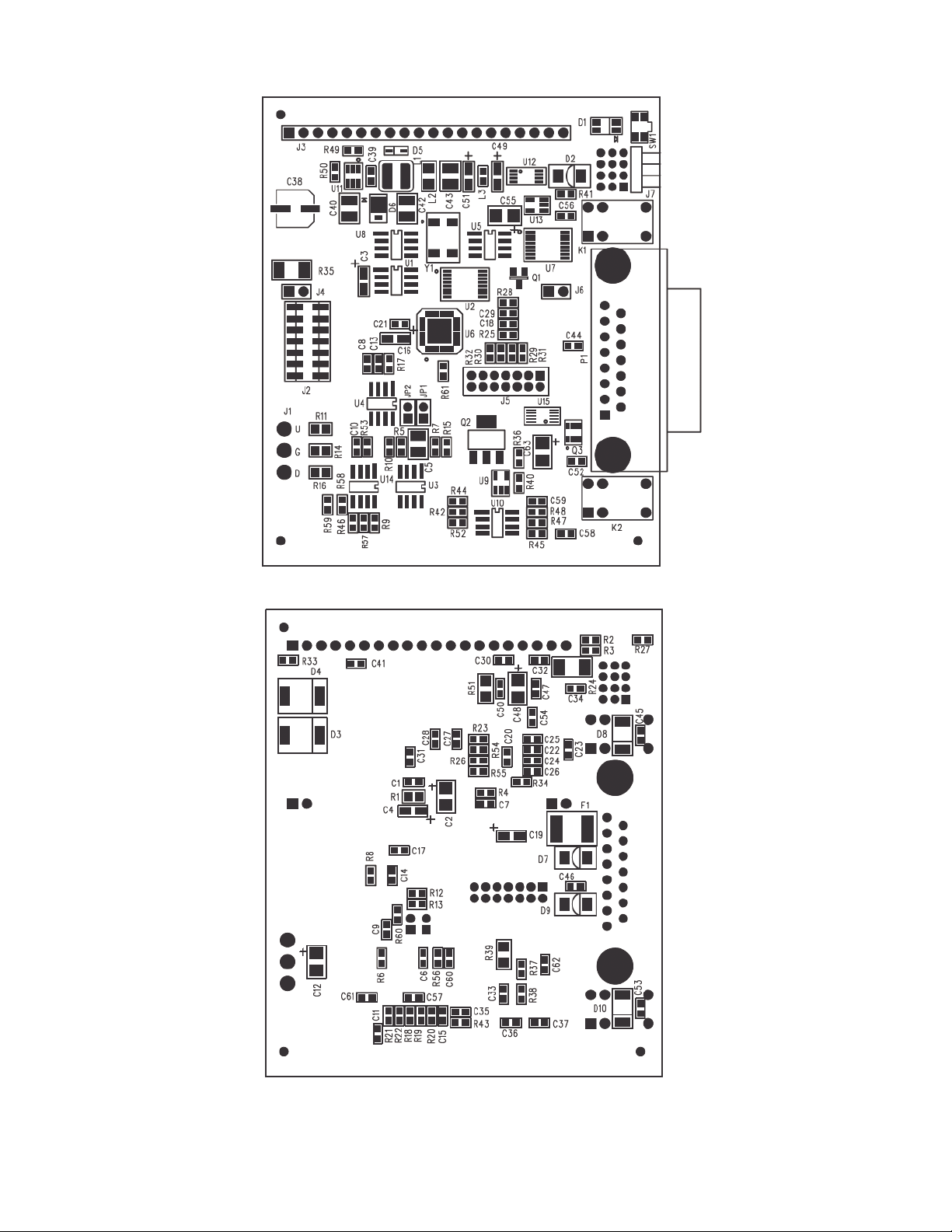
PPENDIX IV - Component Diagram
A
op Component Side
T
Bottom Component Side
Page 18
Page 19
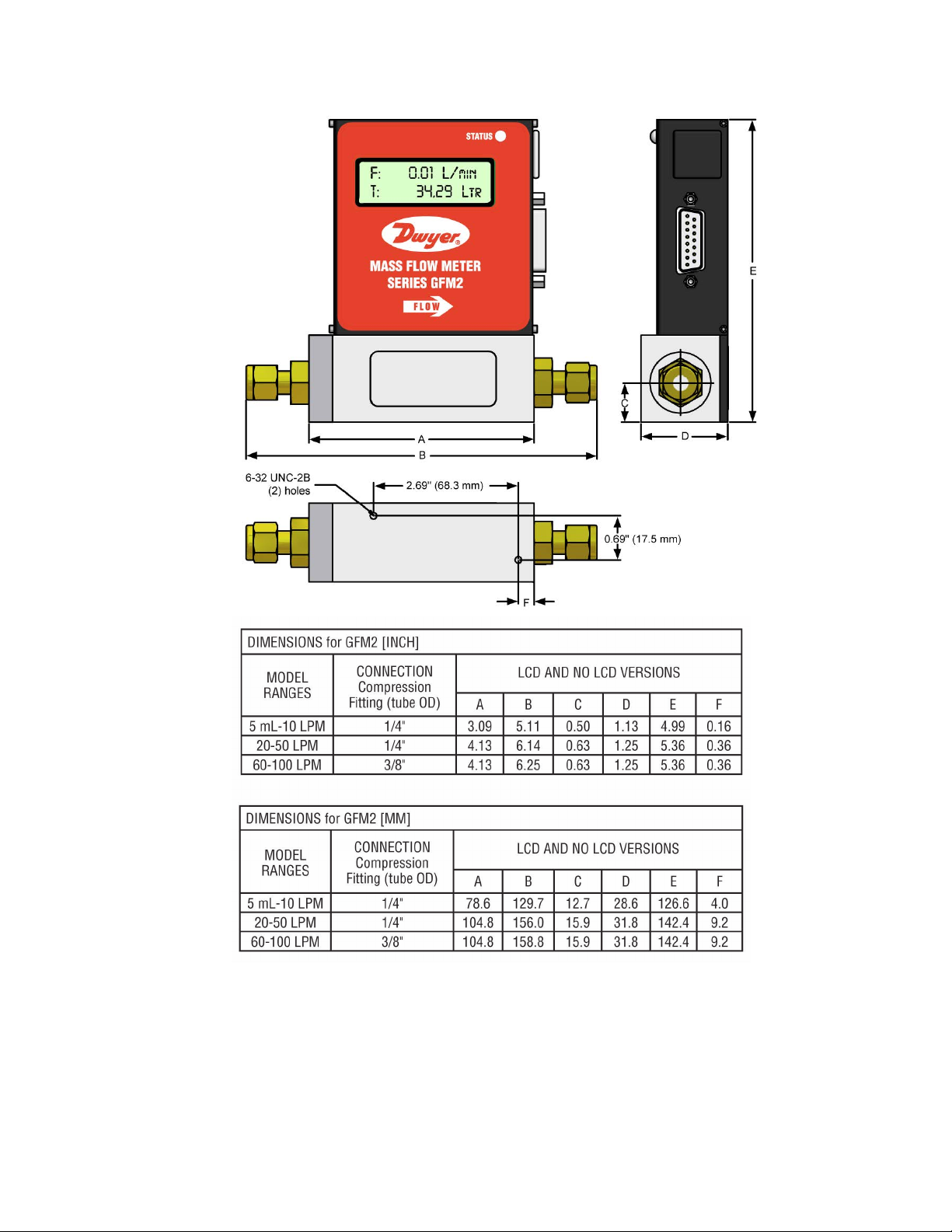
APPENDIX V
Dimensional Drawings
NOTES: Dwyer reserves the right to change designs and dimensions at its sole
discretion at any time without notice. For certified dimensions please contact Dwyer.
APPENDIX VI
MAINTENANCE/REPAIR
Upon final installation of the Series GFM2, no routine maintenance is required. The Series GFM2 is not field serviceable and should be returned if repair is needed. Field
repair should not be attempted and may void warranty (See 1.3).
WARRANTY/RETURN
Refer to “Terms and Conditions of Sales” in our catalog and on our website. Contact customer service to receive a Return Goods Authorization number before shipping the
product back for repair. Be sure to include a brief description of the problem plus any additional application notes.
Page 19
Page 20

Page 20
©Copyright 2013 Dwyer Instruments, Inc. Printed in U.S.A. 5/13 FR# RA-444052-00
DWYER INSTRUMENTS, INC.
Phone: 219/879-8000 www.dwyer-inst.com
 Loading...