

Page 1
User’s
Guide
Shop
online
at
omega.com
omegamanual.info
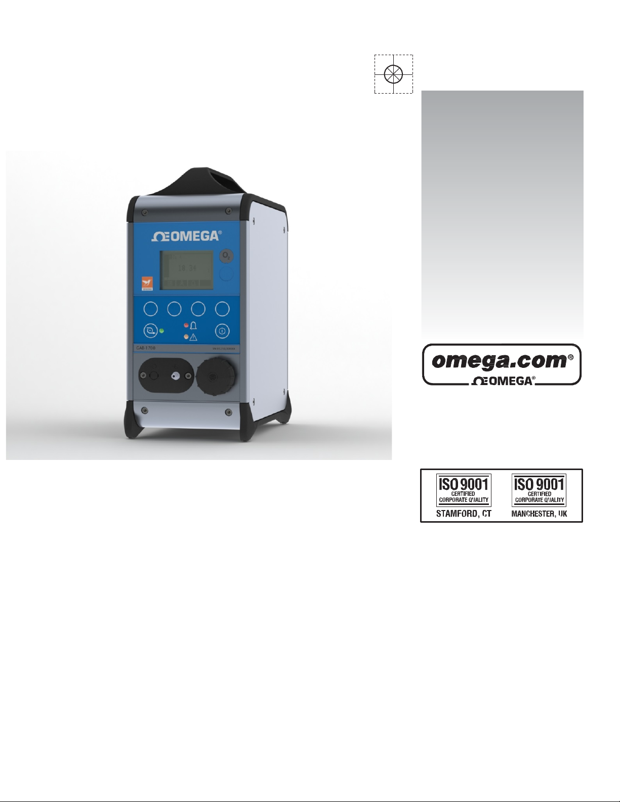
GAB-1700
Benchtop Gas Analyzer
e-mail: [email protected]
For latest product manuals:
Page 2

OMEGAnet®Online Service Internet e-mail
omega.com [email protected]
Servicing North America:
U.S.A.: Omega Engineering, Inc., One Omega Drive, P.O. Box 4047
ISO 9001 Certified Stamford, CT 06907-0047 USA
Canada: 976 Bergar
Laval (Quebec), Canada H7L 5A1
Toll-Free: 1-800-826-6342 TEL: (514) 856-6928
FAX: (514) 856-6886 e-mail: [email protected]
For immediate technical or application assistance:
U.S.A. and Canada: Sales Service: 1-800-826-6342/1-800-TC-OMEGA
Customer Service: 1-800-622-2378/1-800-622-BEST
Engineering Service: 1-800-872-9436/1-800-USA-WHEN
Mexico: En Español: 001 (203) 359-7803 FAX: (001) 203-359-7807
®
®
®
Servicing Europe:
Benelux: Managed by the United Kingdom Office
Czech Republic: Frystatska 184
733 01 Karviná, Czech Republic
Toll-Free: 0800-1-66342 TEL: +420-59-6311899
FAX: +420-59-6311114 e-mail: [email protected]
France: Managed by the United Kingdom Office
Toll-Free: 0800 466 342 TEL: +33 (0) 161 37 29 00
FAX: +33 (0) 130 57 54 27 e-mail: [email protected]
Germany/Austria: Daimlerstrasse 26
D-75392 Deckenpfronn, Germany
Toll-Free: 0 800 6397678 TEL: +49 (0) 7059 9398-0
FAX: +49 (0) 7056 9398-29 e-mail: [email protected]
United Kingdom: OMEGA Engineering Ltd.
ISO 9001 Certified One Omega Drive, River Bend Technology Centre, Northbank
Irlam, Manchester M44 5BD England
Toll-Free: 0800-488-488 TEL: +44 (0)161 777-6611
FAX: +44 (0)161 777-6622 e-mail: [email protected]
It is the policy of OMEGA Engineering, Inc. to comply with all worldwide safety and EMC/EMI
regulations that apply. OMEGA is constantly pursuing certification of its products to the European Ne
Approach Directives. OMEGA will add the CE mark to every appropriate device upon certification
The information contained in this document is believed to be correct, but OMEGA accepts no liability for any
errors it contains, and reserves the right to alter specifications without notice.
WARNING: These products are not designed for use in, and should not be used for, human applications.
.
w
Page 3

GAB-1700 Benchtop Gas Analyzer
Table of Contents
1 DESCRIPTION AND DEFINITIONS ......................................................................................................... 5
1.1 Scope of this manual ................................................................................................................... 5
1.2 Safety information ....................................................................................................................... 5
1.3 Description .................................................................................................................................. 6
1.4 Other product
options
................................................................................................................. 6
2. SPECIFICATION......................................................................................................................................... 9
2.1 General ........................................................................................................................................ 9
2.2 Sample gas ................................................................................................................................. 10
2.3 Calibration gases ....................................................................................................................... 11
2.4 Environmental limits ................................................................................................................. 12
2.5 Performance of the industrial oxygen sensor ........................................................................... 13
2.6 Rechargeable battery (optional feature)................................................................................... 14
2.7 Milliamp outputs (optional feature) ......................................................................................... 14
3 UNPACKING THE GAB-1700 ............................................................................................................... 15
4 GAB-1700 USER INTERFACE .............................................................................................................. 16
4.1 Introduction ............................................................................................................................... 16
4.2 Start-up and measurement screens .......................................................................................... 17
4.3 Soft key legends ........................................................................................................................ 18
4.4 Status icon bar ........................................................................................................................... 19
4.5 Scroll bars .................................................................................................................................. 20
4.6 Menu options/screens and password protection ..................................................................... 20
4.7 The Menu screen ....................................................................................................................... 22
4.8 The Settings screen ................................................................................................................... 23
4.9 The Information screen ............................................................................................................. 23
1
Page 4

GAB-1700 Series Gas Analyzer
4.10 Editing on-screen data............................................................................................................... 24
5 INSTALLATION AND SET-UP ............................................................................................................... 25
5.1 Installation and switch-on ......................................................................................................... 25
5.2 Charging the battery (optional rechargeable battery) .............................................................. 27
5.3 GAB-1700 set-up ....................................................................................................................... 28
5.3.1 Selecting the security level ....................................................................................................... 28
5.3.2 Changing passwords ................................................................................................................. 30
5.3.3 Setting the clock ...................................................................................................................... 31
5.3.4 Changing regional settings ....................................................................................................... 32
5.3.5 Selecting power save mode (for optional rechargeable battery) ............................................ 33
5.3.6 Selecting pump operation (for optional internal sample pump) .............................................. 34
6 GENERAL OPERATION ........................................................................................................................ 36
6.1 Calibrating the GAB-1700 .......................................................................................................... 36
6.2 Taking sample readings ............................................................................................................. 39
6.3 Correcting oxygen measurement for different background gases ........................................... 40
6.3.1 Overview of measurement errors ............................................................................................ 40
6.3.2 Entering a cross-interference compensation ........................................................................... 40
6.4 Configuring the measurement alarms ...................................................................................... 42
6.4.1 Alarm modes and levels ........................................................................................................... 42
6.4.2 Latching/non-latching alarms ................................................................................................... 42
6.4.3 Hysteresis levels ....................................................................................................................... 43
6.4.4 Setting the measurement alarm levels and modes .................................................................. 44
6
.4.5 Enabling/disabling the audible measurement alarm ............................................................... 45
6.5.6 Silencing (muting) the audible measurement alarm ................................................................ 45
6.4.7 Unlatching measurement alarms ............................................................................................. 46
6.4.8 Viewing the measurement alarm status .................................................................................. 46
6.5 Configuring and using the optional milliamp output ................................................................ 47
6.5.1 Overview................................................................................................................................... 47
2
Page 5

GAB-1700 Benchtop Gas Analyzer
6.5.2 Introduction to the milliamp output parameters .................................................................... 48
6.5.3 Set up the milliamp output parameters ................................................................................... 49
6.5.4 Select the Range associated with a measurement .................................................................. 50
6.5.5 Calibrate a milliamp output ...................................................................................................... 51
6.5.6 Check a milliamp output........................................................................................................... 52
6.6 Data logging, serial outputs and printed outputs ..................................................................... 53
6.6.1 Selecting data logging/serial output/printed outputs ............................................................. 53
6.6.2 Configuring the serial output parameters ................................................................................ 54
6.6.3 Introduction to data logging ..................................................................................................... 55
6.6.4 Entering measurement data into the data log ......................................................................... 55
6.6.5 Starting a new data log batch
6.6.6 Outputting the data log ............................................................................................................ 56
6.6.7 Viewing the data log ................................................................................................................. 57
6.6.8 Clearing the data log ................................................................................................................ 57
6.6.9 Printing a sample measurement report ................................................................................... 58
6.7 Adjusting the display ................................................................................................................. 58
6.7.1 Adjusting the backlight timer ................................................................................................... 58
6.7.2 Adjusting the contrast .............................................................................................................. 59
6.8 Switching off the GAB-1700 after use ....................................................................................... 59
7 ROUTINE MAINTENANCE .................................................................................................................. 60
7.1 Cleaning the GAB-1700 ............................................................................................................. 60
7.2 Inspecting the inlet filter element ............................................................................................. 60
7.3 Regenerate/replace the drying agent ....................................................................................... 61
7.4 Use of the GAB-1700 for toxic gas measurements ................................................................... 62
................................................................................................... 56
7.5 Preventative maintenance ........................................................................................................ 63
8 FAULT FINDING .................................................................................................................................. 64
8.1 Introduction to faults and fault messages ................................................................................ 64
8.2 Viewing fault messages ............................................................................................................. 67
3
Page 6

GAB-1700 Series Gas Analyzer
8.3 General fault finding .................................................................................................................. 67
9 STORAGE AND DISPOSAL ................................................................................................................... 73
9.1 Storage ...................................................................................................................................... 73
9.2 Disposal ..................................................................................................................................... 73
APPENDIX .................................................................................................................................................. 74
A1 DATA LOG OUTPUT FORMATS................................................................................................... 74
A2 SERIAL OUTPUT FORMATS ........................................................................................................ 76
A3 PRINTER OUTPUT FORMATS ..................................................................................................... 77
A4 RS232 CONNECTION DETAILS .................................................................................................... 79
A4.1 Overview ................................................................................................................................ 79
A4.2 Connecting the GAB-1700 to a PC ......................................................................................... 79
A4.3 Capturing data using Windows® and HyperTerminal™ ......................................................... 80
A5 MATERIALS IN CONTACT WITH SAMPLE GAS ............................................................................ 81
A6 REPLACING/REGENERATING THE DRYING AGENT .................................................................... 82
A7 DISPOSAL IN ACCORDANCE WITH THE WASTE ELECTRICAL AND ELECTRONIC EQUIPMENT
(WEEE) DIRECTIVE ................................................................................................................................. 83
A8 COMPLIANCE AND STANDARDS INFORMATION ....................................................................... 84
® Drierite is a registered trademark of W A Hammond Co.
® Krytox is a registered trademarks of Dupont.
® Windows and Excel are registered trademarks of Microsoft Corporation.
™ HyperTerminal is a trademark of Hilgraeve Inc.
© This manual is copyright, and no part of it may be
.
Engineering, Inc
.
reproduced
without written approval from Omega
4
Page 7
GAB-1700 Benchtop Gas Analyzer
☞
1 DESCRIPTION AND DEFINI TIONS
1.1 Scope of this manual
This manual provides installation, operation and routine maintenance instructions for
the Omega GAB-1700 series analyzer, abbreviated to “GAB-1700” in the
remainder of this manual.
1.2 Safety information
Read this manual and ensure that you fully understand its content before you attempt
to install, use or maintain the GAB-1700. Important safety information is highlighted in
this manual as WARNINGs and CAUTIONs, which are used as follows:
Warnings highlight specific hazards which, if not taken into
may result in personal injury or
CAUTION
Cautions highlight hazards which, if not taken into account, can result
damage to the GAB-1700 or to other equipment or
This manual also incorporates ‘Be aware of’ information, which is used as
This highlights information which it is useful for you to be aware of -
For example, specific operating conditions, and so on.
WARNING
death.
property.
account,
in
follows:
5
Page 8
GAB-1700 Series Gas Analyzer
1.3 Description
WARNING
This analyzer is not a medical device as defined in the medical
directive 93/42/EEC and is not intended to be used on human beings
diagnosis, prevention, monitoring, treatment or alleviation of
or replacement or modification of the
anatomy.
devices
disease,
for
injury
WARNING
The GAB-1700 must not be used as personal protective
The GAB-1700 is a lightweight gas analyzer, suitable for the needs of field and
laboratory analysis, and light industrial users who require fast, accurate and reliable gas
analysis.
The GAB-1700 uses a paramagnetic transducer to determine the oxygen content of gas
samples in concentrations up to 100%.
The GAB-1700 is simple to operate, with an intuitive user interface (see Section 4).
Gas sample measurements are shown on the GAB-1700 display, and can also be output
to a serial device connected to the GAB-1700, or as optional milliamp outputs.
The GAB-1700 requires little routine maintenance (see Section 7), other than
calibration (which is essential for the accuracy of sample gas measurements) and
regular inspection of the inlet filter element.
equipment.
1.4 Other product
options
The GAB-1700 can be supplied with the following options:
• With an internal sample pump
• With a rechargeable battery
• With a milliamp output
6
the
Page 9
GAB-1700 Benchtop Gas Analyzer
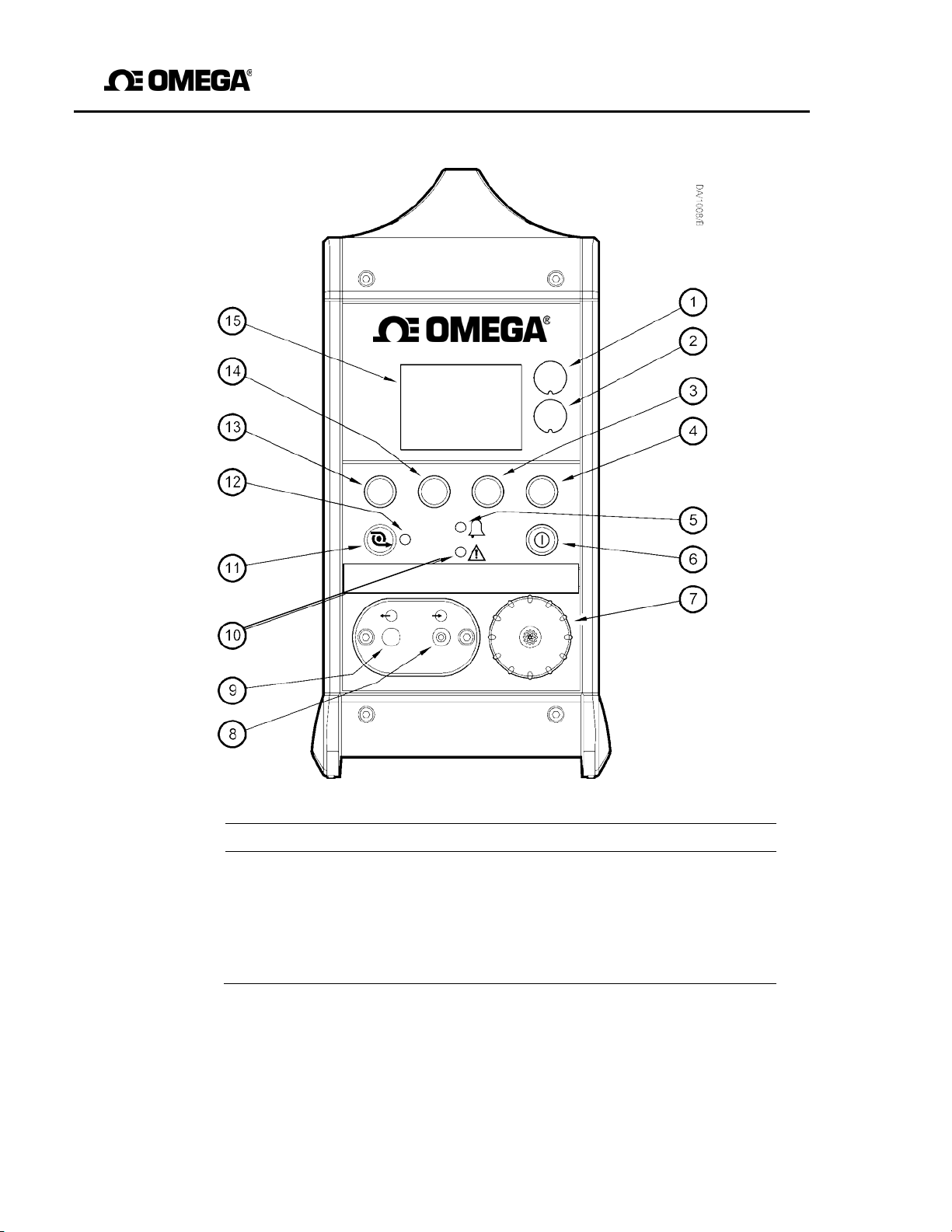
Key Description
Key Description
1.
Sample gas label
9.
Blank
2.
Blank
10.
Fault LED (amber) Sample
3.
Soft key 3
11.
pump key †
4.
Soft key 4
12.
Sample pump LED (green) †
5.
Alarm LED (red)
13.
Soft key 1
6.
Power On/Off key
14.
Soft key 2
7.
Filter retaining cap
15.
Display
8.
Sample gas inlet
GAB-1700 Serial No: 05250A1/00000
7
† Only available if the optional internal sample pump is fitted.
Figure 1 - Front of the GAB-1700
Page 10
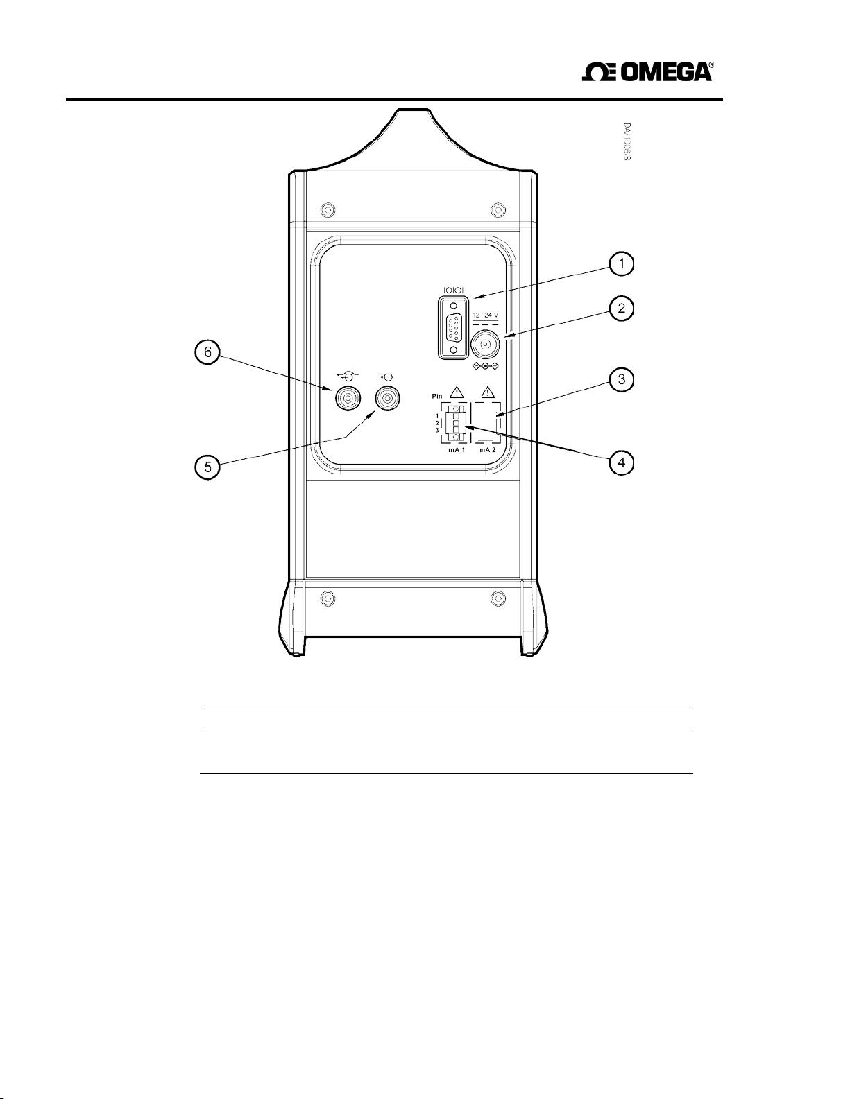
GAB-1700 Series Gas Analyzer
Key Description
Key Description
1.
Serial output port
4.
Milliamp output socket †
2.
Power inlet
5.
Sample gas outlet
3.
Blank
6.
Bypass gas outlet
#
† O nl y fitted if the GAB-1700 includes the optional milliamp output.
# Not fitted to a GAB-1700 with an internal sample pump.
Figure 2 - Rear of the GAB-1700
8
Page 11

GAB-1700 Benchtop Gas Analyzer
Mass (maximum)
2.6 to 3.9 kg (5.7 to 8.6 lbs)
2. SPECIFICATION
requirements of this section and subsequent sections of the manual.
do not, the protection facilities incorporated into the design of
2.1 General
Dimensions:
height x width x depth
WARNING
You must install and use the GAB-1700 in accordance with
may not operate as intended, sample gas
accurate, or the GAB-1700 may be
measurements
damaged.
300 x 150 x 260 mm (12 x 6 x 10.5 in)
the
If
the
GAB-1700
may not be
you
Electrical supply requirements:
Power supply unit
GAB-1700 Analyzer
Minimum gas flow rate
GAB-1700
* As supplied by the power supply unit (through a center pin +ve connector).
† Measured at the sample gas inlet.
9
†
(with internal sample pump)
100 to 240V ac, 47 to 63 Hz (nominal)
12 to 24V dc, 20W (maximum) *
700 ml min
-1
(0.025 ft3 min-1)
Page 12

GAB-1700 Series Gas Analyzer
2.2 Sample gas
WARNING
If the quantity of gas sampled by
the GAB-1700
exposure limit for the gas, the sample should be considered to be toxic. You
risk
must carry out a
gases.
assessment before you use the GAB-1700 with such
The
maximum inlet pressure of such toxic gases is
34.5 kPa gauge (5 psig, 0.35 bar
Pressure range
without internal sample pump 6.9 to 68.9 kPa gauge
(see WARNING above) (1 to 10 psig)
(0.07 to 0.69 bar gauge)
with internal sample pump -3.4 to 3.4 kPa gauge (max) (-
0.5 to 0.5 psig)
(-0.03 to 0.03 bar gauge)
Dew point Less than (ambient temperature minus 10 oC)
Less than (ambient temperature minus 50
Particulate size Less than 2 µm
is above the short term
gauge).
o
F)
10
Page 13

GAB-1700 Benchtop Gas Analyzer
2.3 Calibration gases
Low calibration gas Oxygen-free nitrogen, 99.9% pure
High calibration gas Certified oxygen supply * or instrument quality
†
air
, or other supply (with > 1% oxygen)
Calibration gas flow rate
(with internal sample pump fitted)
Minimum 1 l min
Maximum 2.5 l min
-1
(0.035 ft3 min-1
-1
(0.088 ft3 min-1)
Calibration gas pressure range
6.9 to 68.9 kPa gauge
(1 to 10 psig, 0.07 to 0.69 bar gauge)
* > 99.2% pure oxygen, with nitrogen balance gas.
† The air supply must be clean and dry, and free from oil.
# Without internal sample pump.
The industrial oxygen sensor requires at least a 1% difference in oxygen concentration
between the low and high calibration gases.
11
Page 14

GAB-1700 Series Gas Analyzer
2.4 Environmental limits
Ambient temperature range
o
Operation (analyzer) -10 to +50°C (14 to 122
Operation (power supply unit)
Battery charging
Storage *
-20 to +60°C (-4 to 140
0 to +50°C (32 to 122
+10 to +40°C (50 to 104
F)
o
F)
o
F)
o
F)
Operating ambient pressure range 1.013 x 10² kPa ±10%
(1.013 bar ±10%)
(14.69 psi ±10%)
Operating ambient humidity range 0 to 95% RH, non-condensing
Operating altitude range -500 † to 5000 ‡ meters
†
(-1640
Ingress protection IP40
* Storage below 21 oC (70 oF) is recommended to ensure optimum battery life.
† Below sea level.
‡ Above sea level.
to 16400 ‡ feet)
12
Page 15

GAB-1700 Benchtop Gas Analyzer
2.5 Performance of the industrial oxygen sensor
☞
The display indication given below is the default indication. You can configure
the GAB-1700 to provide other display indications (see Section 6.4).
Display indication Measured volume % oxygen
Full Scale Range 0 to 100% oxygen
Resolution 0.1% oxygen Linearity
± 0.1% oxygen
Intrinsic error (accuracy) ± 0.1% oxygen
Zero drift per week ± 0.2% oxygen
Output fluctuation ± 0.1% oxygen
*
Response time
Without drying tube 15 seconds
With drying tube fitted 25 seconds
Flow effect
†
± 0.1% oxygen
Zero temperature coefficient ± 0.2% oxygen per 10 oC (18 oF)
Span temperature coeffic ient ± 0.3% oxygen per 10
Tilt effects ± 0.15% oxygen per 15
Pressure effects Directly proportional to ambient barometric
#
pressure
* T
† Within sample gas supply pressure range specified in Section 2.2.
# A 1% change in ambient barometric pressure will result in a 1% change in
at 68.9 kPa gauge (10 psig, 0.69 bar gauge) supply pressure.
90
sample reading.
o
C (18 oF)
o
of tilt
13
Page 16

GAB-1700 Series Gas Analyzer
2.6 Rechargeable battery (optional feature)
Battery type Lithium ion Time
to charge (from empty) 4 hours *
Operating life (from fully charged) 8 to 35 hours
Service life Approximately 300 to 500 discharge/
* This is the charge time with the GAB-1700 switched off. With the GAB-1700 switched
on, charge time depends on ambient conditions, and on the GAB-1700 configuration and
usage.
† Battery operating life depends on the GAB-1700 configurati on (that is, the options that
2.7 Milliamp outputs (optional feature)
are fitted), and how the GAB-1700 is used.
☞ Lithium ion batteries have no ‘memory effects’, so you can charge the battery, from
any charge level, for any length of time and for often as you like, without affecting
the battery’s service life.
To ensure the optimum service life of the battery, we recommend that you charge the
battery after each session of operation, and that you store the GAB-1700 when not in
use in a cool environment: see Section 2.4.
Maximum load resistance
†
charge cycles (depending on ambient
conditions)
1 kΩ
Minimum isolation voltage
500 V
Output range
Normal sample measurement
Fault condition
Under range
†
0 to 20 mA or 4 to 20 mA *
0 mA or 21.5 mA *
Less than 4 mA
Cable requirements
Type Multi-strand twisted pair with overall screen
Maximum size 1.5 mm
2
16 AWG
* User selectable: see Sections 6.6.2 and 6.6.3.
† Only available when the 4 to 20 mA output range is selected:
See Sections 6.6.2 and 6.6.3.
14
Page 17

GAB-1700 Benchtop Gas Analyzer
3 UNPACKING THE GAB-1700
1. Remove the GAB-1700 and any other equipment from its packaging.
2. Remove the protective plastic cover from the sample gas inlet on the front of
GAB-1700 (see Figure 1).
3. Remove the protective plastic cover from the sample gas outlet on the rear of the
GAB-1700 (see Figure 2).
4. Remove the protective plastic cover from the bypass gas outlet (if fitted) on the rear
of the GAB-1700 (see Figure 2).
5. Inspect the GAB-1700 and the other items supplied, and check that they are not
damaged. If any item is damaged, immediately contact Omega.
6. If you do not intend to use the GAB-1700 immediately:
• Refit the protective plastic covers to the gas inlet, the sample gas outlet and the
bypass gas outlet (if fitted).
• Place the GAB-1700 and any other equipment supplied back in its
protective packaging.
• Store the GAB-1700 as described in Section 9.1.
the
Otherwise, read Section 4 (User Interface), and then continue from Section 5
onwards to install, set up, and use the GAB-1700.
☞
15
Retain the shipping documentation and packaging for future use (for example,
return of the GAB-1700 to Omega for servicing or repair).
CAUTION
You must remove the protective plastic covers as specified in Steps 3 and
above before you use the GAB-1700. If you do not, you may damage
GAB-1700 when you try to pass calibration or sample gases through
the
it.
4
Page 18

GAB-1700 Series Gas Analyzer
4 GAB-1700 USER INTERFACE
☞
Throughout this manual, reference is made to product options (such as
"rechargeable battery") which must be specified at the time of purchase.
Associated menus and menu options will not be available if your GABdoes not have the corresponding product options.
4.1 Introduction
The GAB-1700 user interface comprises the following (shown on Figure 1):
Power On/Off key Use this key to switch on the GAB-1700 (see
Display Shows various screens: see Section 4.2 onwards.
Soft keys The function of each of the soft keys depends on the
Alarm LED On when an alarm condition exists: see Section 6.4.
Fault LED On when a fault condition exists: see Section 8.
Sample pump key * Use this key to switch the sample pump on and off:
See Section
Sample pump LED * Flashes when the sample pump is operating:
See Section
* This key and LED are only operational if an internal sample pump is fitted.
The GAB-1700 also has an audible alarm which will go on (emit a tone):
• On initial switch-on: see Section 5.1.
• When a measurement alarm condition is detected (if the audible measurement
alarm is enabled): see Section 6.4.
• When a fault condition is detected: see Section 8.
Section 5.1) or to switch it off (see Section 6.8).
screen currently being shown on the display: see
Section 4.2.
5.3.6.
5.3.6.
1700
16
Page 19
GAB-1700 Benchtop Gas Analyzer
4.2 Start-up and measurement screens
When you first switch on the GAB-1700, a ’start-up screen’ is displayed while the
GAB-1700 carries out a self-test.
The start-up screen shows a ‘self-test time elapsed/remaining’ indicator, and messages
identifying the tasks being carried out as part of the self-test:
• The screen will initially display the message "System Check".
• The Measurement screen is then displayed, as shown in Figure 3.
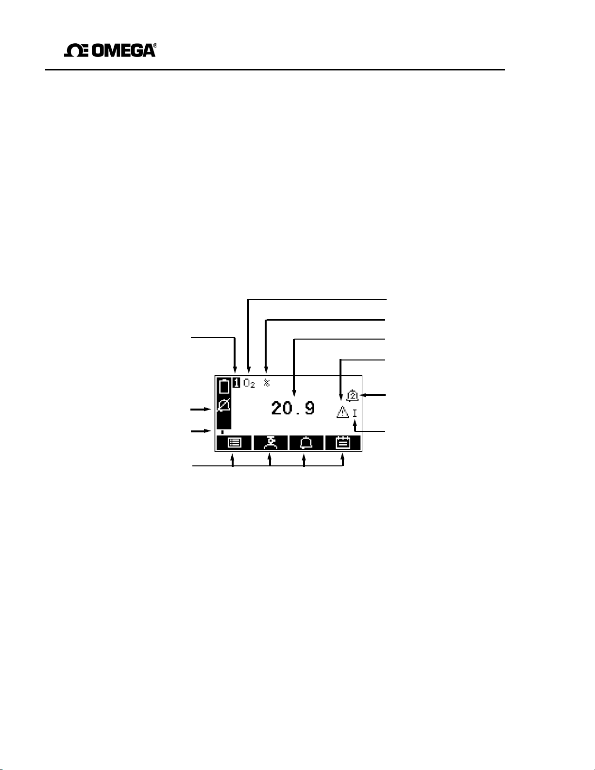
(A) 1-measurement screen:
Gas being measured
Measurement units
Transducer number Current measurement
("1" always shown)
Fault icon: see Section 8
Status icon bar Alarm icon: see Section 6.4.1
(see Section 4.4)
Software health Milliamp Range:
Indicator See Section 6.5.1
Soft key legends
*Optional feature
Figure 3 - The Measurement screen
17
Page 20
GAB-1700 Series Gas Analyzer
☞
During normal GAB-1700 operation, the software health indicator continuously
moves from left to right and then back again, below the status icon bar. If the
indicator stops moving, this means that the GAB-1700 is not operating correctly,
and you must refer to Section 8.
☞
If no soft key is pressed for 10 minutes, the Measurement screen will be
automatically displayed. (You will also then have to enter the password again
to access any password-protected screens: refer to Figure 4 and to Section 4.6.)
4.3 Soft key legends
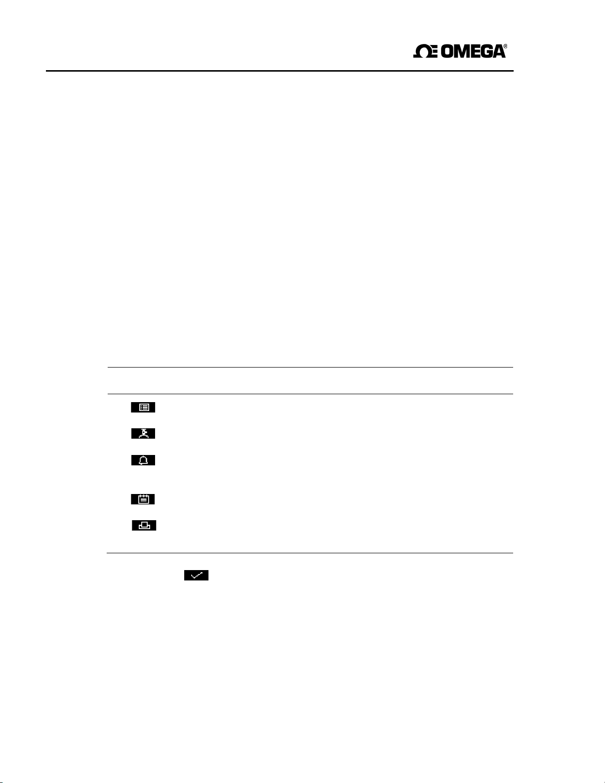
The four soft key legends at the bottom of the Measurement screen (Figure 3)
correspond to the four soft keys on the front of the GAB-1700. (The first legend
corresponds to the function of soft key 1, the second legend corresponds to the
function of soft key 2, and so on).
On the Measurement screen, the soft key functions are as follows:
Legend Meaning Function (when soft key pressed)
Menu Displays the Menu screen: see Section 4.7.
Calibrate *
Alarm *
Displays the Calibrate screen: see Section 6.1.
Displays the Alarm option screen: see
Section 6.4.4.
Logging
Print
†
†
Displays the Data logging screen: see Section 6.6.
Produces a printed sample measurement report:
see Section 6.6.9.
* These soft keys are ‘shortcuts’ to these menus, which can also be selected by
pressing the soft key with the corresponding menu option highlighted on the
Menu screen: see Section 4.7.
† If you have selected printed outputs (see Section 6.6.1), the ‘Print’ legend is
shown instead of the ‘Logging’ legend.
18
Page 21
GAB-1700 Benchtop Gas Analyzer
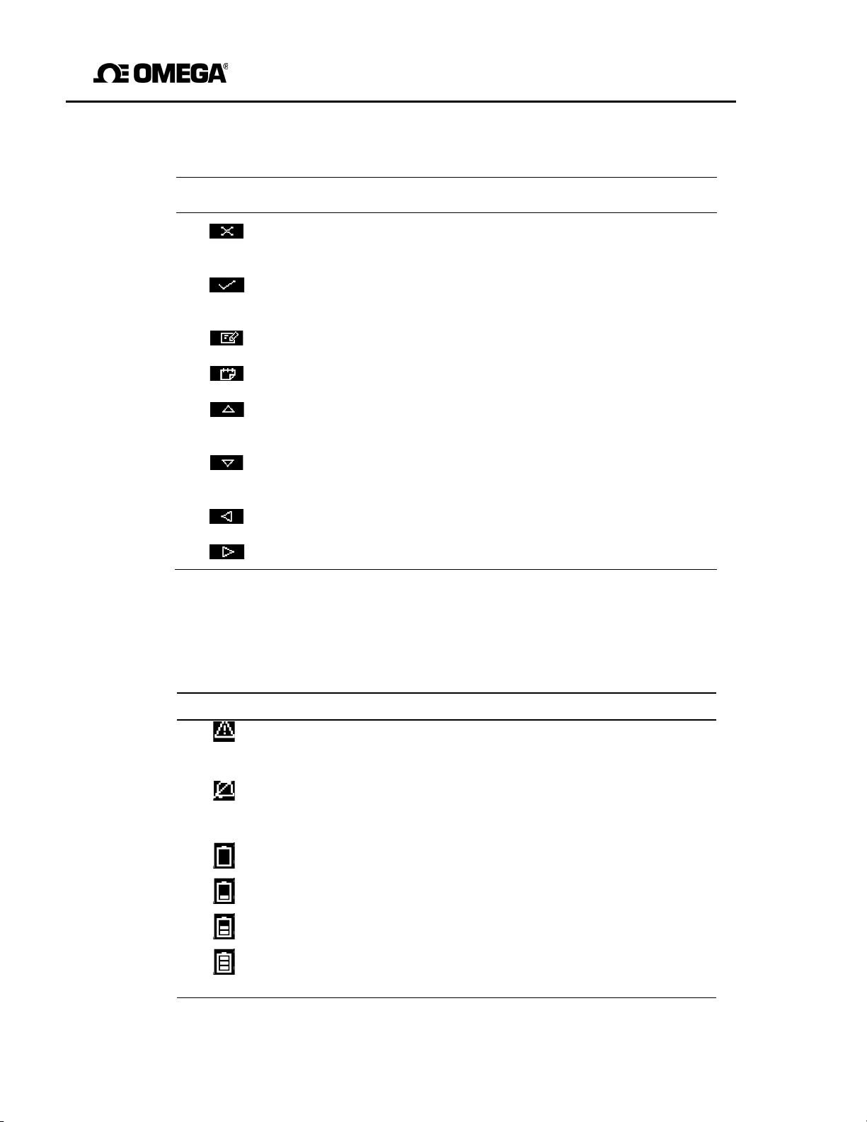
Other soft key legends which are used on the various screens are as follows:
Legend Meaning Function (when soft key pressed)
4.4 Status icon bar
The st atus icon bar appears on all screens. The icons which can be shown and their
meanings are as follows:
Icon Meaning
Indicates that a fault has been detected by the GAB-1700
Back Cancels the current screen and displays the
previous screen in the menu structure.
Accept
Accepts the currently selected option or data.
(A new screen may be displayed accordingly.)
Edit
Batch
Up
Allows the highlighted data to be edited.
Starts a new batch (for data logging).
Moves the cursor up a list (or increases a digit
during editing).
Down
Moves the cursor down a list (or decreases a
digit during editing).
Left
Right
Moves the cursor left.
Moves the cursor right.
refer to Section 8.
Indicates that the audible alarm is disabled:
refer to Section 6.4.5
*
*
*
*
Battery less than 10%
Battery 10% to 32% full.
Battery 33% to 65% full.
Battery 66% to 100% full.
full.
* These icons will only be shown on a GAB-1700 with the optional
rechargeable battery fitted. See Section 5.2 for more information.
19
Page 22

GAB-1700 Series Gas Analyzer
☞
4.5 Scroll bars
When the ‘battery less than 10% full icon starts to flash, this indicates that the
rechargeable battery is virtually empty. The GAB-1700 will automatically
down approximately 15 seconds after the icon starts to flash.
On some screens (for example, see Figure 5), there may be more options available
than can be shown on the screen, and you have to scroll down the screen to view all of
the options: this is identified by a scroll bar at the right-hand side of the screen.
The height of the wide part of the scroll bar gives an indication of what proportion (of a ll
the options) are currently shown on the screen. As you scroll up or down the options
(using the and soft keys ), the wide part of the scroll bar will also m ove on
the screen, indicating approximately where the currently displayed options are, within the
complete list of options. For example, compare the scroll bars in Figures 5 and 13.
4.6 Menu options/screens and password protection
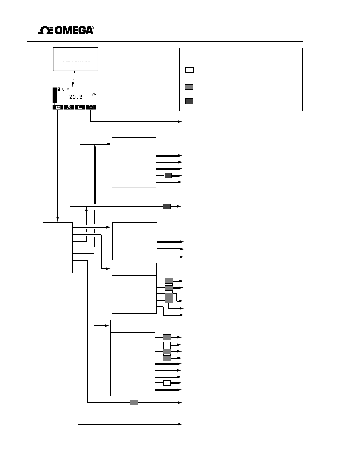
The menu structure of the GAB-1700 is shown in Figure 4, which shows that some of the
options/screens are password protected.
When an option/screen is password protected, this means that the correct
corresponding
Password protection operates as follows:
• The first time you try to access a password-pr otected option/screen, you will be
prompted for the corresponding password. You must then enter the correct
password (using the editing method described in Section 4.10) before the
option/ screen can be displayed.
• If you have already entered the cor responding password, you will gain access to
all options/screens protected by that password immediately (you do not need to
enter the password again).
password has to be entered before the
option/screen
shut
can be accessed.
☞
20
Once you have entered a password, it remains active until 10 minutes
after the last soft key is pressed. After this, the password becomes
inactive; you must re-enter the password to access password-protected
options/screens again.
Page 23
O
Initiating…
View the data log [6.6.7]
Set milliamp parameters [6.5]
Set serial output parameters [6.6.2]
View system information [4.9]
Denotes the option/screen is always
protected by the supervisor password
Data log
Set up
Calibrate
Alarm
Settings
Service
Faults Set up
Serial type
Unit selection
X-interference
Pump
21
GAB-1700 Benchtop Gas Analyzer
(Start-up screen) [X.Y.Z] Refers to the section in the manual
Denotes the option/screen can be
(Measurement screen) [4.2]
Add measurement to data log [6.6.4]
Start new data log batch [6.6.5]
Produce printed report [6.6.9] *
Alarm
Mute
Unlatch
View
Set up
Audible alarm
Data log
View log
Output log
Clear log
mA output
Settings
Serial output
Password
Clock
Regional
Backlight
Contrast
Power save
Security
Information
Check milliamp output [6.5.6]
* If printed outputs selected [6.6.1]
Silence the audible measurement alarm [6.4.6]
Unlatch a latched measurement alarm [6.4.7]
View the measurement alarm status [6.4.8]
Set up the measurement alarms [6.4.4]
Enable/disable the audible measurement
alarm [6.4.5]
Calibrate the GAB-1700 [6.1]
Output the data log [6.6.6]
Clear the data log [6.6.8]
Select serial output/data logging/printed
outputs [6.6.1]
Set for volume %
Enter a cross-compensation error [6.3.2]
Select pump operation mode [5.3.6]
Change the password(s) [5.3.2]
Set the date/time [5.3.3]
Change regional settings [5.3.4]
Adjust the backlight timer [6.7.1]
Adjust the display contrast [6.7.2]
Select/deselect power save [5.3.5]
Select the security level [5.3.1]
Calibrate milliamp output [6.5.5]
View current faults [8.2]
Figure 4 - The GAB-1700 menu structure
protected by the supervisor password
Denotes the option/screen can be
protected by the operator password
Page 24
GAB-1700 Series Gas Analyzer
4.7 The Menu screen
☞
Some of the menu screens referenced below may not be available: refer to
the note at the start of Section 4.
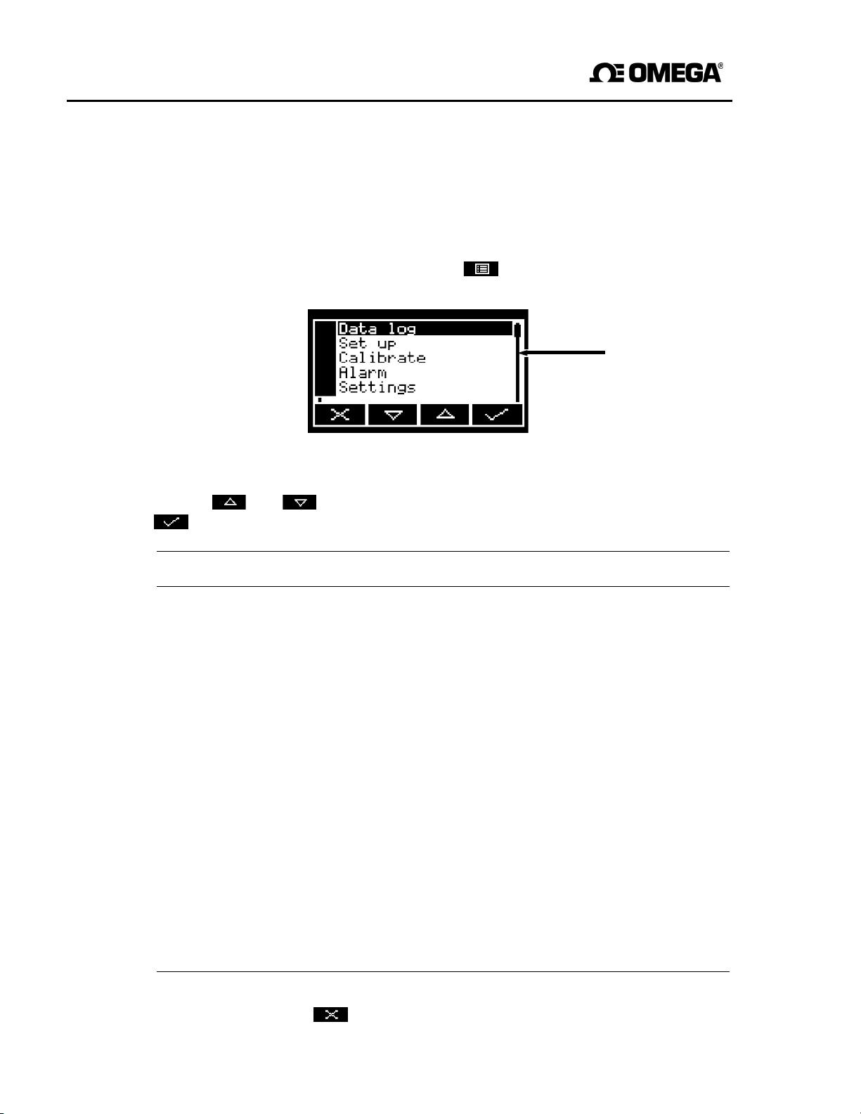
The Menu screen (see Figure 5) provides access to other screens in the menu
structure, and is displayed by pressing the soft key when the Measurement
screen is displayed.
Scroll bar:
Section
4.5
see
Figure 5 - The Menu
Use the and soft keys to highlight the required screen option, then press the
soft key to display the selected screen:
Screen Use Section
Data Log Select this screen to view, output or clear the data log. 6.6.6 to
Set up Select this screen to configure the (optional) 6.5.3,
milliamp output, select serial output, data logging or 6.6.1,
printed outputs, or introduce a cross- interference 6.3.2
correction.
Calibrate Select this screen to calibrate the GAB-1700. 6.1
Alarm Select this screen to set up the measurement alarms, 6.4.4
or to silence (mute) the audible measurement alarm.
Settings Select this screen to change GAB-1700 settings 4.8
(password, display language and so on).
Service Select this screen to calibrate or check the 6.5.5,
(optional)
milliamp output. 6.5.6
Faults Select this screen to view current faults. 8.2
Alternatively, press the soft key to display the Measurement screen again.
screen
6.6.8
22
Page 25
GAB-1700 Benchtop Gas Analyzer
Screen
Use
Section
4.8 The Settings screen
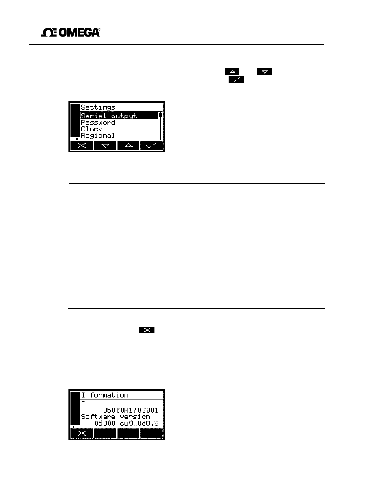
The Settings screen is shown in Figure 6. Use the and soft keys to
highlight the required screen option, then press the soft key to display the
selected screen, as shown below.
Figure 6 – The Settings screen
Serial output Configuring the serial output parameters 6.6.2
Password Changing the password. 5.3.2
Clock Setting the clock time and/or date. 5.3.3
Regional Changing regional settings (language and so on). 5.3.4
Backlight Adjusting the backlight timer duration. 6.7.1
Contrast Adjusting the contrast of the screen. 6.7.2
Power save * Selecting/deselecting ‘power save’ operation. 5.3.5
Security Selecting the security level. 5.3.1
Information Viewing GAB-1700 system information. 4.9
* Only available on a GAB-1700 with the optional rechargeable battery fitted.
Alternatively, press the soft key to display the Menu screen again.
4.9 The Information screen
The content on the information screen (such as the GAB-1700 serial number and
the version of the operating software) may be useful to the Omega support team.
Figure 7 – Typical information screen
23
Page 26
GAB-1700 Series Gas Analyzer
After viewing (and if necessary recording) the information shown on the screen, press the
soft key to display the Settings screen again, or press and hold the soft key to
show the Measurement screen again.
☞
You may be asked to provide the information from this screen to the
Omega support team; for example, to aid fault diagnosis.
4.10 Editing on-screen data
A common method is used for editing data shown on all of the different
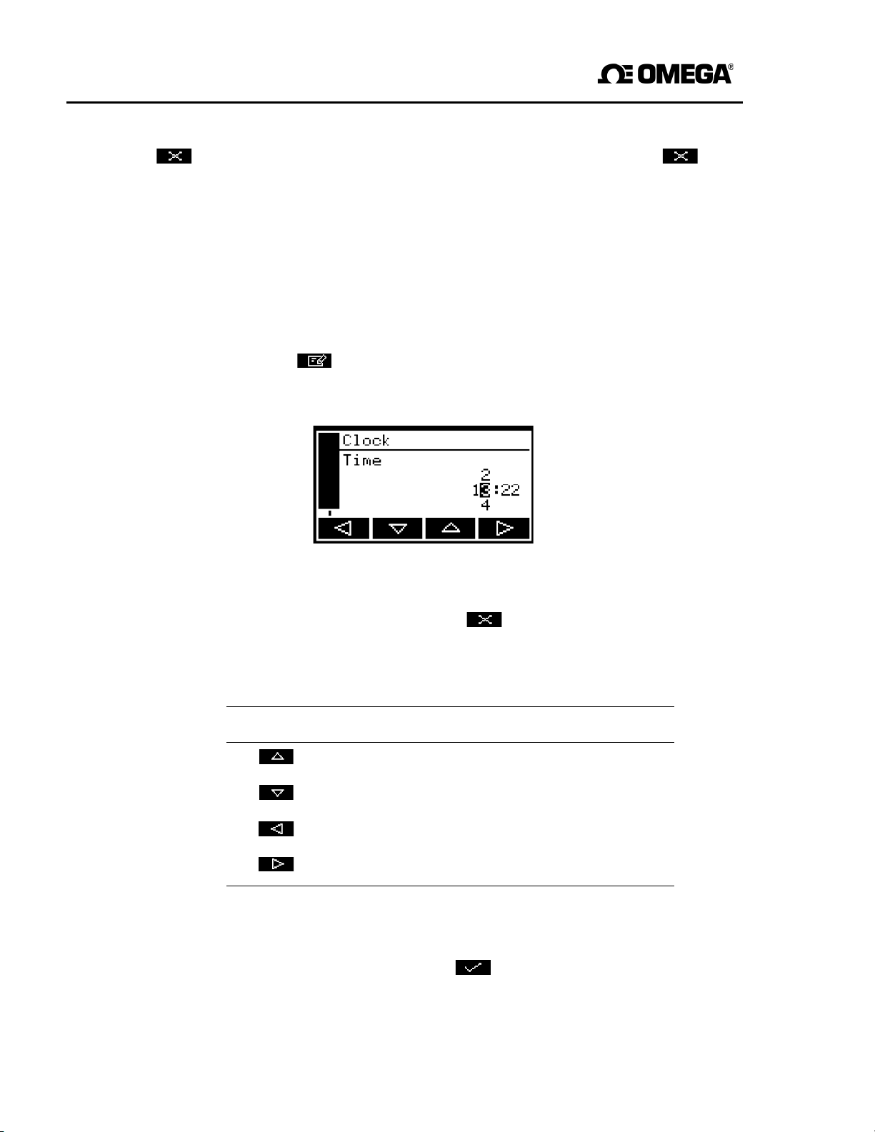
When
you press the soft key to edit an item of data, the screen changes to show
the corresponding edit screen, with the first digit highlighted; a typical edit screen is
shown in Figure 8:
When the first digit is highlighted, press the soft key to exit the menu without
changing the data.
Alternatively, use the soft keys to edit the data as follows:
Soft key Function
Increases the highlighted digit by 1.
Figure 8 - A typical edit
screen
screens.
Decreases the highlighted digit by 1
Moves the cursor left to the previous digit.
Moves the cursor right to the next digit.
Note that the figures above and below the highlighted digit show the digits above and
below the currently highlighted value.
When the last digit is highlighted, press the soft key to enter the new data.
☞
When editing numerical values, the decimal point appears between digits
"9" and "0".
24
Page 27
GAB-1700 Benchtop Gas Analyzer
5 INSTALLATION AND SET-UP
5.1 Installation and switch-on
Ensure that the cables and tubes that you connect to the GAB-1700
are routed so that they do not present a trip hazard to
Ensure that the electrical installation of the GAB-1700 and the
supply unit conforms with all applicable local and national
Sample and calibration gases may be toxic or asphyxiant. Ensure
the external connections are leak free at full operating pressure
before
Sample and calibration gases may be toxic or asphyxiant. Ensure that the
GAB-1700 sample, bypass gas and calibration ‘T’ piece (if used) outlets are
vented to an area where they will not be a hazard to people.
Sample and calibration gases may be toxic or asphyxiant. To prevent
the
build-up of such gases, ensure that the GAB-1700 is only used in
Do not use the GAB-1700 in an area subject to high levels of
sudden jolts. If you do, sample measurements may not be accurate,
1. Place the GAB-1700 in a suitable operating location, within easy reach of a
suitable electrical supply outlet.
2. If necessary (if sample or calibration gases are toxic or asphyxiant) or if
required:
• Use quick-connect fittings to connect a suitable sized tube to the sample gas
outlet (on the rear of the GAB-1700: see Figure 2).
GAB-1700 may be
WARNING
WARNING
safety
WARNING
requirements.
you use sample or calibration
WARNING
WARNING
well-ventilated
CAUTION
damaged.
environment.
gases.
people.
power
electrical
vibration
or
that
a
or
the
• Use quick-connect fittings to connect a suitable sized tube to the bypass gas
outlet (if fitted, on the rear of the GAB-1700: see Figure 2).
25
Page 28
GAB-1700 Series Gas Analyzer
3. If you have fitted tubes to the sample gas outlet and/or bypass gas outlet, route the
ends of the tubes so that they can freely vent to atmosphere.
☞
The two outlets can be left to vent to local atmosphere. However if you
do fit a tube to one or both of the outlets, the tube(s) must be suitably
sized so that the gases can vent from the GAB-1700 without overpressuring the GAB-1700 or the tubes.
4. You may connect a PC (personal computer) or other device to the serial
connector, refer to Appendix A4.
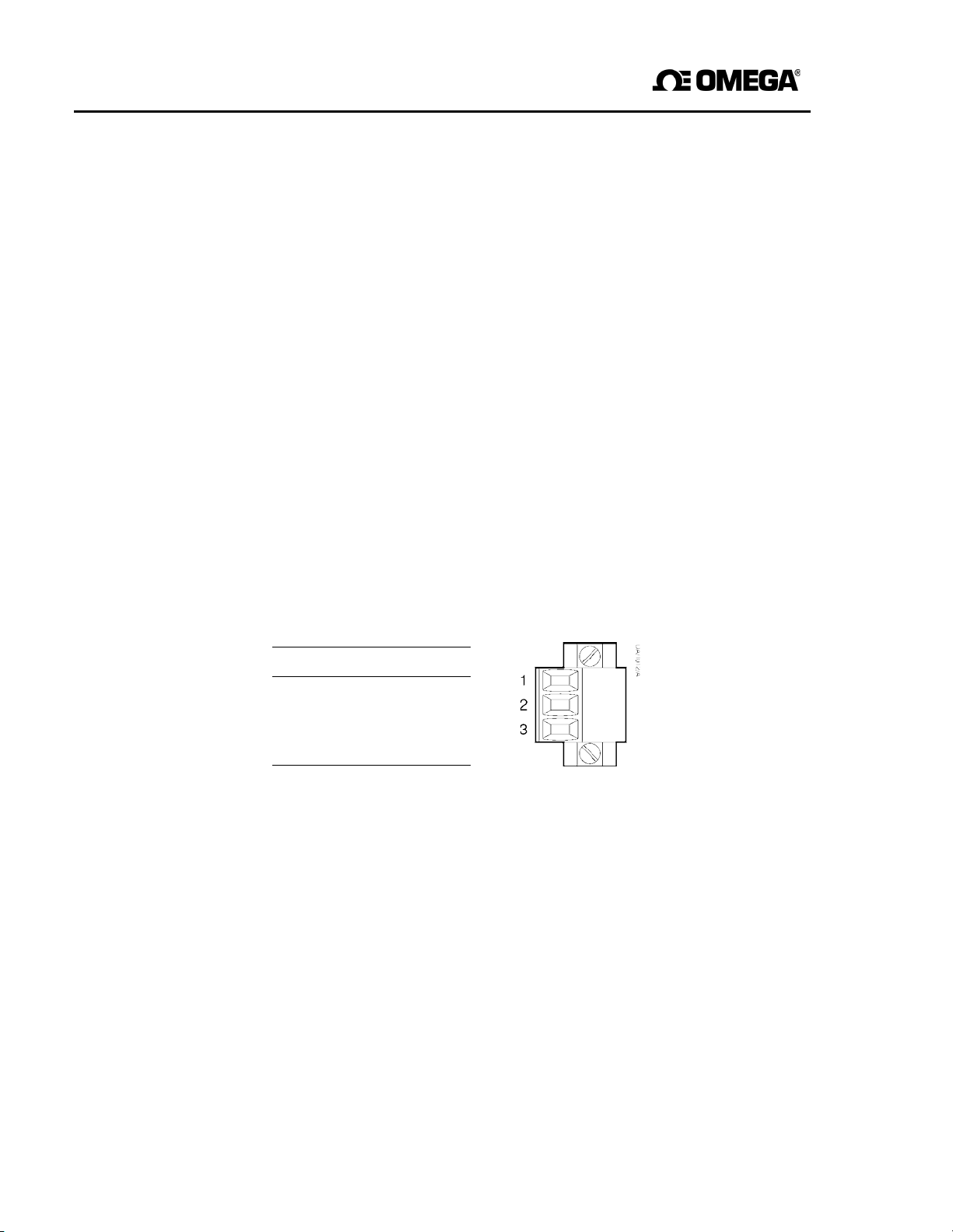
5. If your GAB-1700 is configured to provide an optional milliamp output:
• Connect the wires in your cable to the screw terminals on the milliamp interface
connector supplied: refer to Section 2.7 for the cable requirements, and refer to
Figure 9 below for the connection requirements.
• Fit the interface connector to the corresponding milliamp output connector on the
rear of the GAB-1700 (see Figure 2), and secure with the two captive screws on
the interface connector.
Pin
1 +ve
2 -ve
Use
3 screen
Figure 9 - milliamp interface connector
6. Fit the power outlet on the power supply unit to the power socket on the rear of the
GAB-1700.
7. Fit the power supply unit plug to a suitable electrical supply outlet.
8. Press and hold the Power On/Off key on the front of the GAB-1700 for at least
2 seconds to switch the GAB-1700 on.
☞
When the GAB-1700 is switched on, the Alarm LED, the Fault LED
and the audible alarm will all go on for 1 second to demonstrate that
they are functioning correctly, and will then go off again.
26
Page 29

GAB-1700 Benchtop Gas Analyzer
5.2 Charging the battery (optional rechargeable battery)
The first time you use a GAB-1700 with the optional rechargeable battery, you should
leave the GAB-1700 connected to the electrical supply for at least 4 hours to fully charge
the battery.
When the battery is fully charged, you can leave the GAB-1700 connected to the
electrical supply, or you can disconnect the electrical supply and continue to use the
GAB-1700 powered by the battery.
☞
During normal use, the battery icon on the status icon bar of the display will identify the
level of charge within the battery (see Section 4.4).
You can charge the battery as and when required during normal use. To charge th e
battery, simply connect the GAB-1700 to an external electrical supply outlet.
☞
☞
We recommend that you charge the battery as soon as possible after the
‘battery less than 10% full ’ icon is displayed.
While charging the status icon bar will continually show the ‘battery less
than 10% full’, ‘battery 10 to 32% full’, ‘battery 33 to 65% full’ and ‘battery 66
to 100% full’ icons in sequence.
You can charge the battery with the GAB-1700 switched on or off.
However, charging will take longer when the GAB-1700 is switched on.
27
Page 30

GAB-1700 Series Gas Analyzer
5.3 GAB-1700 set-up
When you switch on the GAB-1700, a ’start-up screen’ is first displayed (see
Section 4.2), then the Measurement screen (Figure 3) is displayed.
When the Measurement screen is displayed, you can set up the GAB-1700 as
described below.
5.3.1 Selecting the security level
You can configure the GAB-1700 to provide any of three levels of security:
Security level Function
Low None of the options/screens are password protected *.
Standard Some of th e options/screens are protected b y a
supervisor
High Some of th e options/screens are protected by a
supervisor password and some of the options/screens
are protected by an operator password
* Except for the ‘change the password(s)’ and ‘select the security level’
options/screens: see below.
† The supervisor password can also be used to access options/screens protected
by the operator password: see notes below.
☞
The ‘change the password(s)’ and ’select the security level’ screens/options are
always protected by the supervisor password, regardless of the security
level selected. This is to ensure that unauthorized personnel cannot change the
security level and password(s) and so lock out the GAB-1700 from other users.
password.
†
.
☞
☞
Refer to Figure 4 to see the
menu structure.
☞
28
The supervisor password provides access to all password protected options/
screens. That is, if you have selected the ‘high’ security level and are
prompted to enter the operator password, you can also access the option/
screen by entering the supervisor password.
Password protection can be used to prevent adjustment of the clock by
unauthorized persons, so ensuring the validity of measurement times and
the ’time since last calibration’ history.
options/screens
As supplied, the security level is set to ‘high’, the supervisor password is set to
"2000" and the operator password is set to "1000". We recommend that
you select your required security level and change the password(s) as
described below to provide additional protection.
which can be
password-protected
within the
Page 31
GAB-1700 Benchtop Gas Analyzer
Before the GAB-1700 is used for sample measurement, we recommend that you select
the security level (low, standard or high: see Section 4.6) most suitable for the way in
which the GAB-1700 will be used by you and/or your personnel.
Use the following procedure to select the required security level:
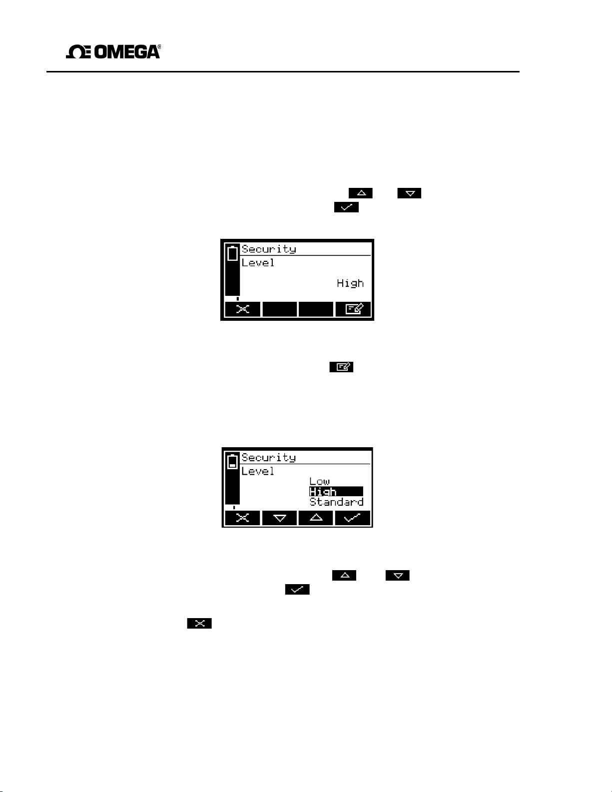
1. With the Settings screen displayed, use the and soft keys to highlight the
"Security" menu option, then press the soft key. The Security level screen
will then be displayed showing the currently selected level: see Figure 10.
Figure 10 - The Security level screen
2. To change the security level, press the soft key. You will then be prompted to
enter the supervisor password.
3. Once the supervisor password has been entered correctly, the Security select
screen will be displayed (see Figure 11), with the currently selected security
level highlighted.
Figure 11 - The Security select screen
4. To change the security level, use the and soft keys to highlight the
required level, then press the soft key. The Security level screen will then be
29
displayed again, showing the newly selected security level.
5. Press the soft key twice to display the Menus screen again.
Page 32
GAB-1700 Series Gas Analyzer
operator password screen, press the
soft key, then enter the new
5.3.2 Changing passwords
☞
If you change a password, ensure that you record the new
password
and store it somewhere safe. Otherwise, if you cannot recall the new
password, you will have to contact Omega for assistance.
Use the following procedure to change the supervisor and operator passwords:
1. With the Measurement screen displayed, press the soft key to display the
Menu
screen, use the and soft keys to highlight the "Settings" menu
option, then press the soft key. The Settings screen will then be displayed
(see Figure 6).
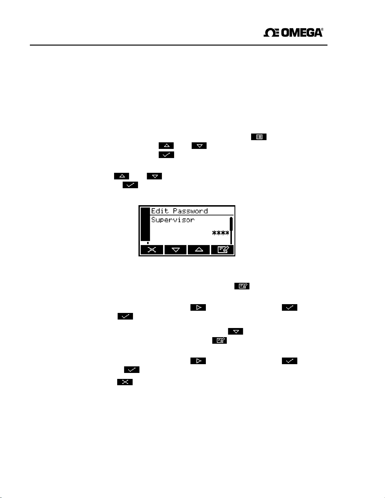
2. Use the and soft keys to highlight the "Password" menu option, then
press the soft key. The Edit supervisor password screen will then be
displayed with the supervisor password shown, as shown in Figure 12.
Figure 12 - The Edit supervisor password
screen
3. To change the supervisor password, press the soft key, then enter the new
password: use the editing method described in Section 4.10.
4. When you enter the last digit, the soft key changes to the soft key.
Press the soft key to enter the new supervisor password value.
5. To change the operator password, press the soft key to display the edit
password: use the editing method described in Section 4.10.
6. When you enter the last digit, the soft key changes to the soft key.
Press the soft key to enter the new operator password
value.
7. Press the soft key to display the Settings screen again.
30
Page 33
GAB-1700 Benchtop Gas Analyzer
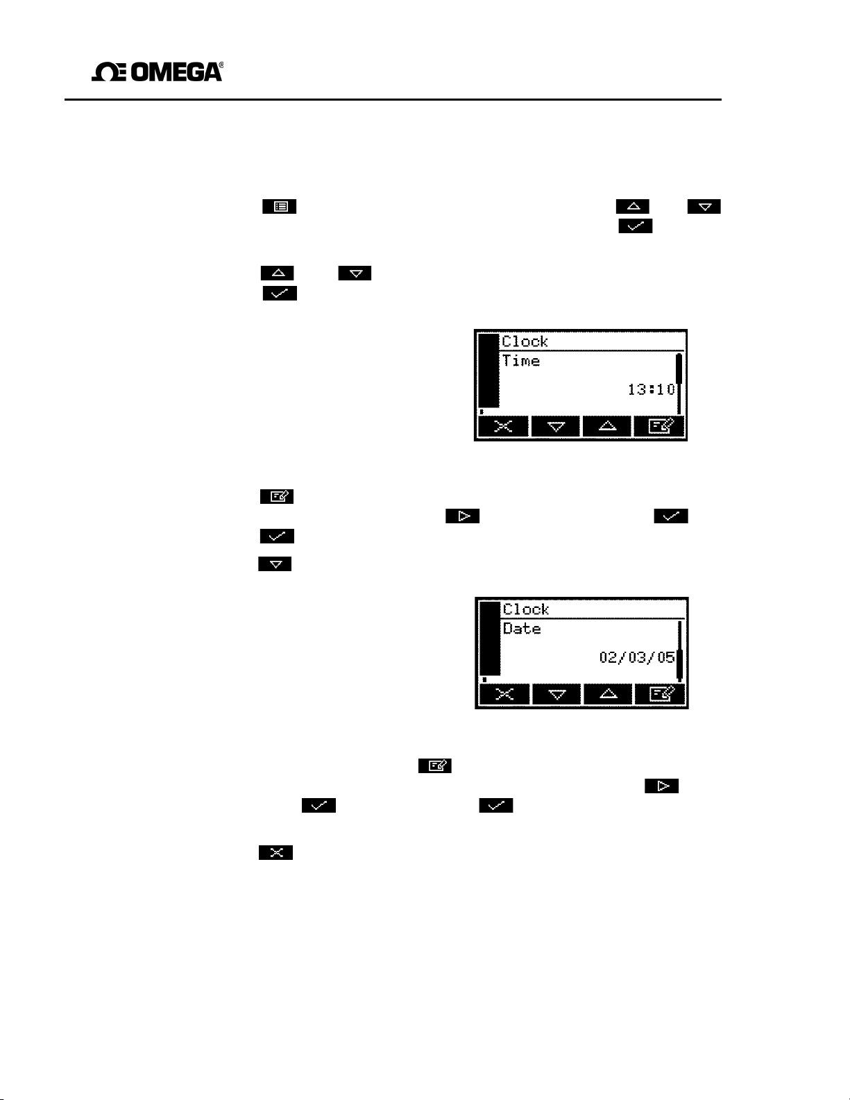
.3.3 Setting the clock
5
Use the following procedure to set the date and time:
1. Press the soft key to display the Menu screen, use the and soft
keys to highlight the "Settings" menu option, then press the soft key. The
Settings screen will then be displayed.
2. Use the and soft keys to highlight the "Clock" menu option, then
press the soft key. The Clock (time) screen will then be displayed, as
shown in Figure 13.
☞
in 24-hour format.
Time is always shown
3. Press the soft key, then edit the displayed time as descr ibed in Section 4.10.
4. Press the soft key to show the Clock (date) screen, as shown in Figure 14.
5. To change the date, press the soft key, then edit the displayed date as
6. Press the soft key twice to display the Menus screen.
When you change the last digit, the soft key changes to the soft key.
Press the soft key to show the Clock (time) screen again.
You can change this
☞
described in Section 4.10. When you change the last digit, the soft key
changes to the soft key. Press the soft key to show the Clock (date)
screen again.
format from day/month/
year to month/day/year:
refer to Section 5.3.3.
Figure 13 - The Clock (time)
Figure 14 - The Clock (date)
screen
screen
☞ The date format can be set to your regional preference (’day/month/year’ or
month/day/year’ format): refer to Section 5.3.3.
☞
On a GAB-1700 without an optional rechargeable battery: once set, date
and time will remain set until approximately 1 week after the GAB-1700 has
been disconnected from the electrical supply. If the GAB-1700 is left
connected to the electrical supply, date and time will remain set indefinitely,
even if the GAB-1700 is switched off.
31
Page 34
GAB-1700 Series Gas Analyzer
5.3.4 Changing regional settings
You can configure the following GAB-1700 regional settings so that the information shown
on the various screens is better suited to your local conventions:
Setting Options available
Language Various languages are supported.
Date format Day/Month/Year * or Month/Day/Year.
Decimal format Use of "." (full stop) or "," (comma) as the
decimal point.
* Default option
To change the regional settings:
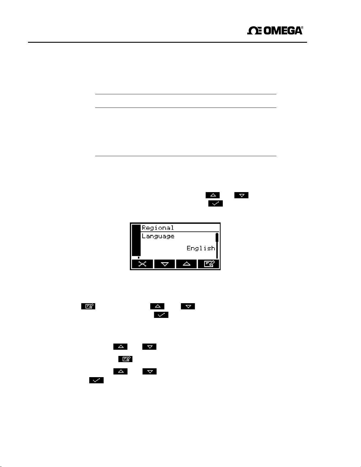
1. With the Settings screen displayed, use the and soft keys to highlight the
"Regional" menu option, then press the soft key. The first Regional
settings option screen will then be displayed, as shown in Figure 15.
.
Figure 15 - The Regional settings (language) option screen
2. This screen shows the first regional option (Language). If necessary, press the
soft key, use the and soft keys to highlight the required display
language, then press the soft key.
3. If required, for each of the other two selectable options (date format and decimal
format):
• Use the and soft keys to select the corresponding option screen.
• Press the soft key.
• Use the and soft keys to highlight the required option, then press the
soft key.
32
Page 35
GAB-1700 Benchtop Gas Analyzer
5.3.5 Selecting power save mode (for optional rechargeable battery)
If the GAB-1700 has the optional rechargeable battery, you can select the ‘power save’
mode of operation, to conserve battery power. When power save mode is selected, the
GAB-1700 will automatically switch off after 30 minutes has elapsed during which no key
has been pressed.
To select/deselect power save mode:
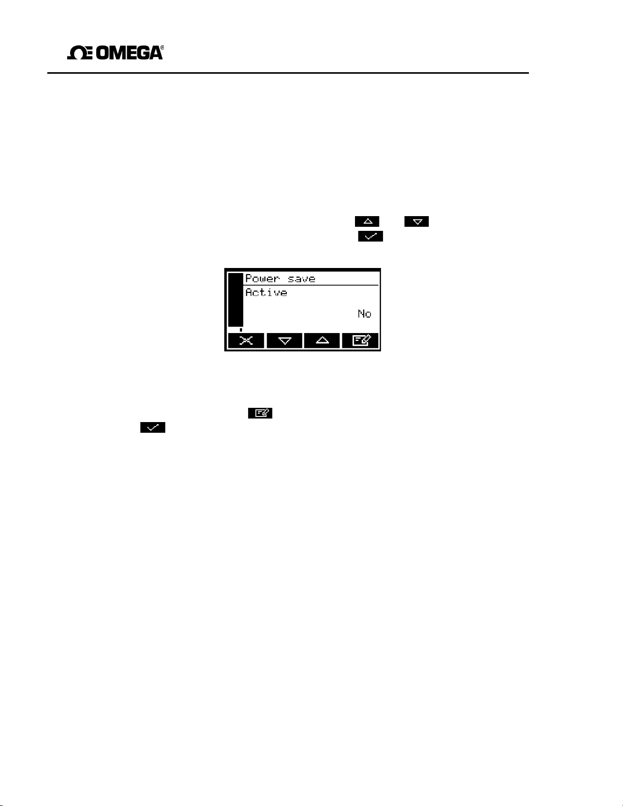
1. With the Settings screen displayed, use the and soft keys to highlight the
"Power
save" menu option, then press the soft key. The Power save option
screen will then be displayed, as shown in Figure 16.
Figure 16 - The Power save option screen
2. "No" or "Yes" on this screen identifies whether power save is selected or not. If
necessary, press the soft key to select the alternative setting, then press the
soft key.
☞
33
Power save mode is automatically disabled when the GAB-1700 is
connected (through the power supply unit) to the electrical supply.
Page 36
GAB-1700 Series Gas Analyzer
5.3.6 Selecting pump operation (for optional internal sample pump)
If your GAB-1700 has an internal sample pump fitted, you must select how you want
to operate the pump before you start to make sample measurements. The pump can be
operated using one of two methods:
Method Pump operation
Manual When you press the Pump key on the front of the GAB-1700
(see Figure 1), the sample pump will start. You must then
press the key again, to stop the pump.
Timed When you press the Pump key on the front of the GAB-1700
(see Figure 1), the sample pump will start, operate for a
preset time, and then stop. If you select this m ode, you must
To select the required method of sample pump operation:
also specify the time for which the pump should operate.
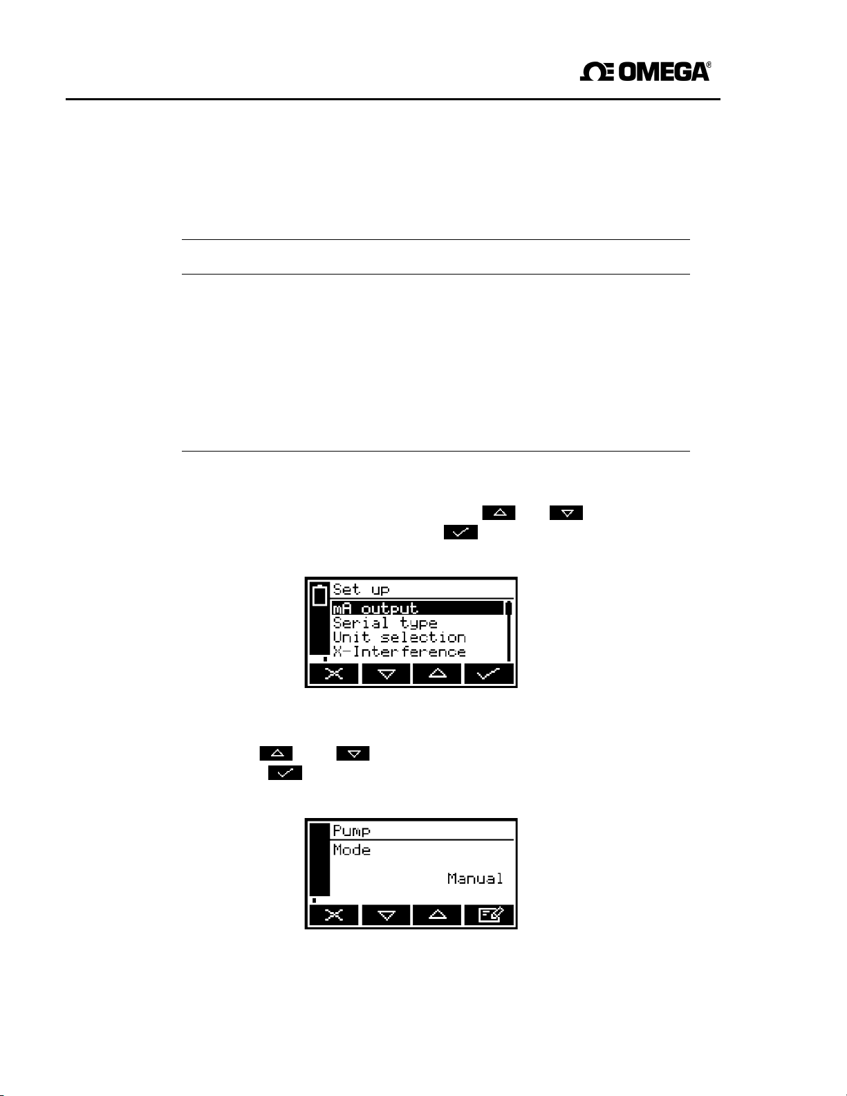
1. With the Settings screen displayed, use the and soft keys to highlight the
"Set up" menu opt ion, then press the soft key. The Set up screen will then be
displayed, as shown in Figure 17.
screen
Figure 17 - The Set up
2. Use the and soft keys to highlight the "Pump" menu option, then
press the soft key. The Pump mode screen will then be displayed, as
shown in Figure 18 (which shows manual pump operation selected).
Figure 18 - The Pump mode
34
screen
Page 37
GAB-1700 Benchtop Gas Analyzer
3. If you want to change the method of sample pump operation, press the soft key,
use the and soft keys to highlight the alternative menu option, then
press the soft key.
If you have selected Timed pump operation, you must then continue at Step 4
below to set the pump operation time.
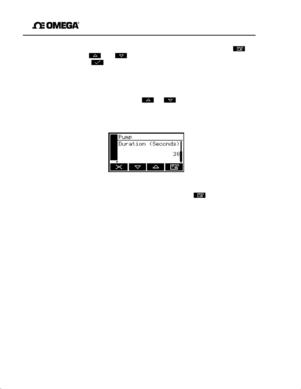
4. With the Pump mode screen displayed (as described above), and with "Timed"
operation selected, press the or soft key so that the Pump duration
screen is displayed, as shown in Figure 19.
This screen shows the currently selected duration (that is, the time for which the
pump will operate when you press the Pump key).
Figure 19 - The Pump duration
screen
5. If you want to change the duration, press the soft key then edit the
displayed duration as described in Section 4.10.
☞
Pump duration can be set in the range 1 to 999 seconds.
35
Page 38
GAB-1700 Series Gas Analyzer
6 GENERAL OPERATION
This gas analyzer may be used with sample and/or calibration gases
present a toxic hazard, where the local gas
or long-term exposure limits (and very high dilution rates may
safely vent the gases used). You must therefore ensure
aware of the potential hazards of the gases used, carry
assessment and create suitable safe working
hazards, and ensure that these working practices
whenever the analyzer is used. If in doubt about
gases to be used with the analyzer, seek
Sample and calibration gases must be as specified in Sections 2.2 and 2.3.
your sample or calibration gas pressures and/or flow rates are above
specified in Sections 2.2 and 2.3, you must regulate the gases
6.1 Calibrating the GAB-1700
☞
☞
☞
☞
The pressure of your calibration gas supply must be the same as the
pressure of the gases to be sampled. If the pressures are different, sample
gas measurements may not be accurate.
If you do not allow calibration gas to pass through the GAB-1700 for 3 to 5
minutes before you start the calibration procedure, the measurement
system in the GAB-1700 may not be fully purged of other residual gases, and
the calibration may not be accurate.
Do not knock or move the GAB-1700 during calibration. If you do, the
calibration measurements may be affected.
For a standard GAB-1700 with a sample pump, the following calibration
procedure assumes that you have selected manual pump operation. If you
have selected timed pump operation, you must ensure that the pump operation
time is set correctly to allow calibration gas to pass through the GAB-1700 for
sufficient time: refer to Section 5.3.6 for more information.
WARNING
specialists/safety
CAUTION
they enter the GAB-1700
concentrations
practices
the
potential hazards of the
expert
consultants.
advice from appropriate
.
may
exceed
be
that
you are fully
out
your own risk
based on these
are
complied with
externally,
that
short-
needed to
If
those
before
36
Page 39
GAB-1700 Benchtop Gas Analyzer
You must calibrate the GAB-1700 as part of the initial set-up (see Section 5.3), and
whenever the GAB-1700 has been moved to a different environment. We also
recommend that you calibrate the GAB-1700 at each power up, to avoid measurement
errors due to changes in ambient conditions. Calibrate the GAB-1700 as follows:
1. If you have a GAB-1700 without a sample pump:
• Connect your calibration gas supply to the sample gas inlet on the front of the
GAB-1700 (see Figure 1). Ensure that the calibration gas pressure is as
specified in Section 2.3.
• Allow the calibration gas to pass through the GAB-1700 for 3 to 5 minutes, then
continue at Step 3.
2. If you have a GAB-1700 with a sample pump:
• Connect the branch on the calibration ‘T’ piece to the sample gas inlet on the front
of the GAB-1700 (see Figure 1)
• Connect a suitable vent pipeline to one end of the calibration ‘T’ piece;
alternatively, if it is safe to do so, leave the end of the ‘T’ piece open to vent to
the local atmosphere.
• Connect your calibration gas supply to the other end of the ‘T’ piece.
• Switch on the sample pump (see Section 5.3.6), allow the calibration gas to
pass through the GAB-1700 for 3 to 5 minutes, then continue at Step 3.
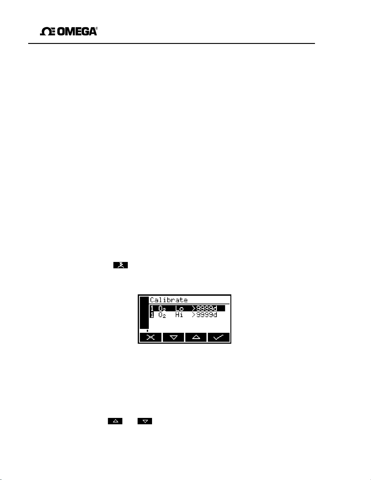
3. Press the soft key on the Measurement scr een (or select the "Calibrate"
option from the Menu screen) to display the Calibrate screen (see Figure 20).
Figure 18 - The Pump mode
screen
Note that the "9999d" field of the screen shown in Figure 20 will identify the
period of time that has elapsed since the last calibration, and can be in any of the
following forms:
• 9999d specifying days • 9999h specifying hours
• 9999m specifying minutes • Any combination of these.
4. Use the and soft keys to select the required calibration, that is:
• ’Lo’ (low calibration gas: for example, nitrogen for the oxygen sensor).
• ’Hi’ (high calibration gas: for example, oxygen for the oxygen sensor).
37
Page 40
GAB-1700 Series Gas Analyzer
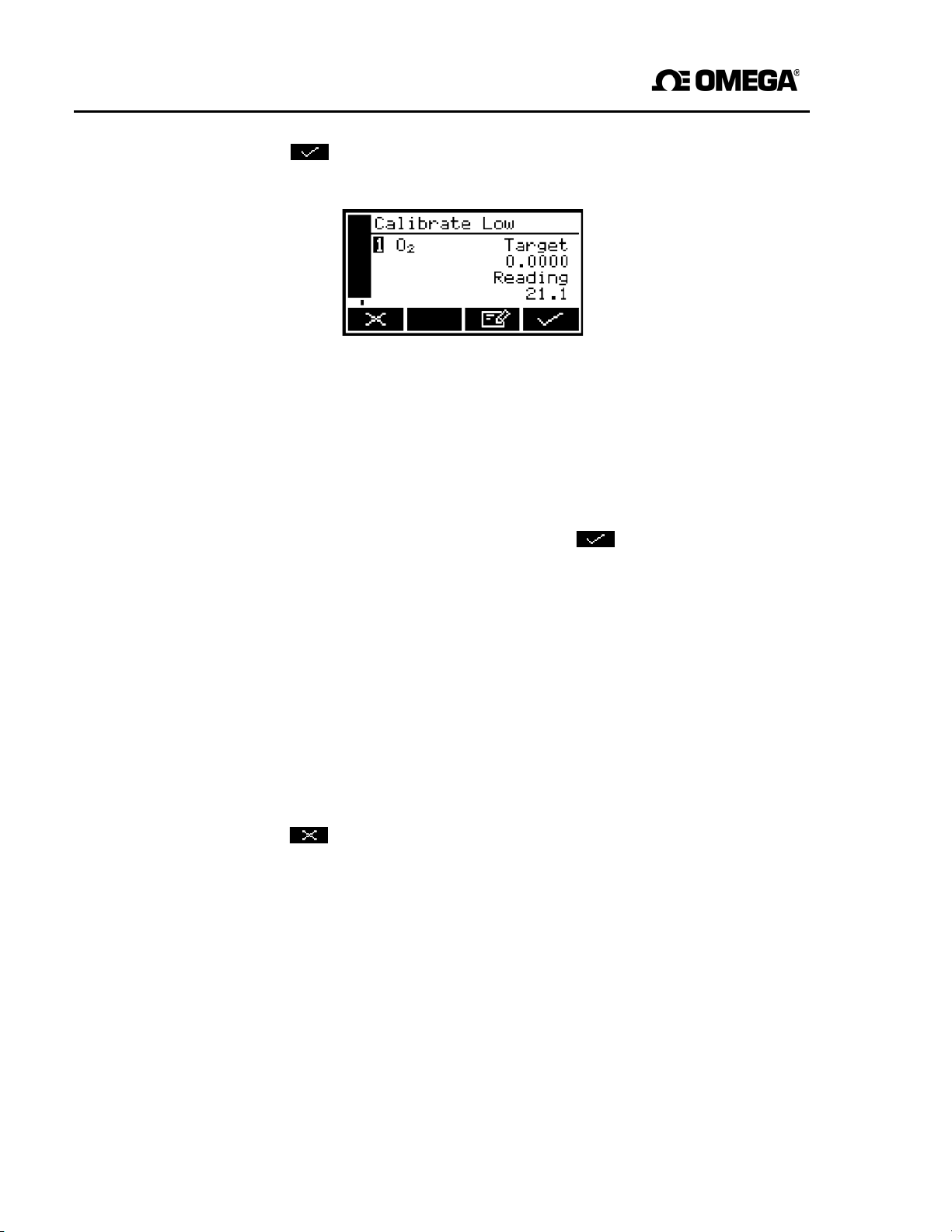
5. Press the soft key. The Calibrate target value screen will then be shown
(see Figure 21), identifying the target value and the current reading.
Figure 21 - The Calibrate
value
screen
target
6. If the target value is not that for the calibration gas which you are using, change the
target value to the required value: use the edit method in Section 4.10.
☞
Refer to Sections 2.2 and 2.3 for the required pressures, flow rates (if
applicable) and concentrations of the calibration gases.
7. When the current reading is stable, press the soft key. The GAB-1700 will
38
then carry out the specified calibration.
8. If you have a standard GAB-1700 with a sample pump, switch the pump off
(if necessary: see Section 5.3.6).
9. Disconnect the calibration gas supply from the sample gas inlet or the calibration
‘T’ piece.
10. Repeat Steps 1 to 9 of this section for the second calibration for the specific
sample gas.
11. On a GAB-1700 with the optional sample pump: disconnect your vent pipeline
(if fitted) from the calibration ‘T’ piece, then disconnect the ‘T’ piece from the sample
gas inlet.
12. Press the soft key to display the Measurement screen again.
Page 41

GAB-1700 Benchtop Gas Analyzer
6.2 Taking sample readings
☞ Depending on how you have configured the measurement alarms, and on
how you connect the sample gases to the GAB-1700, a measurement alarm
may occur when you change sample gases as described below.
☞
1. If necessary, calibrate the GAB-1700: see Section 6.1.
2. Ensure that the Measurement screen is displayed: see Section 4.
3. Use the quick-connect fitting supplied to connect the sample gas supply to the
4. If your GAB-1700 has a sample pump, start the sample pump: see
5. Wait until the measurement shown on the screen has stabilized, then take note of
6. If your GAB-1700 has a sample pump and you have selected manual pump
7. Turn off the sample gas supply, or disconnect it from the sample gas inlet on the
Repeat Steps 3 to 7 as necessary, for different gas samples to be measured.
Unless your sample gases are known to be dry, you must connect the drying
tube (supplied with the GAB-1700) to the sample gas inlet on the GAB1700, and then connect your sample gas supply to the drying tube.
sample gas inlet on the front of the GAB-1700 (see Figure 1).
Section 5.3.6.
the reading.
operation, stop the sample pump: see Section 5.3.6.
front of the GAB-1700.
39
Page 42

GAB-1700 Series Gas Analyzer
Background gas
Error
Background gas
Error
Argon
-0.22%
Krypton
-0.49%
6.3 Correcting oxygen measurement for different background gases
☞
If you are measuring oxygen in a background of nitrogen or air, you do not
need to correct the measurements.
6.3.1 Overview of measurement errors
For an oxygen sensor, the composition of any typical background gas in the gas
sample will have a negligible effect on the GAB-1700 measurement. For a GAB-1700
which has been ’Lo’ calibrated with nitrogen and ’Hi’ calibrated with oxygen, the crossinterference errors (that is, oxygen measurement errors) in gases which contain 100%
of a specific background gas will be as shown below:
Carbon dioxide
Halothane
Helium
-0.26%
-1.93%
-0.29%
Neon
Nitrous oxide
Xenon
-0.15%
-0.20%
-0.92%
Note that the error is directly proportional to the concentration of the background gas in
the sample being measured, and in most cases can be ignored.
If you cannot ignore the error, you can use the procedure in Section 6.3.2 to enter a
compensation to correct for the error.
6.3.2 Entering a cross-interference compensation
☞
Cross-interference compensation is disabled during calibration, and is not
applied to the values shown in Figure 21. All other outputs (that is, serial or
milliamp outputs) remain compensated.
Use the following procedure to enter a compensation to correct for an oxygen
measurement error:
1. Press the soft key to display the Menu screen, use the and soft
keys to highlight the "Set up" menu option, then press the soft key. The Set up
screen will then be displayed (see Figure 17).
40
Page 43
GAB-1700 Benchtop Gas Analyzer
2. Use the and soft keys to highlight the "X-Interference" menu option,
press
then
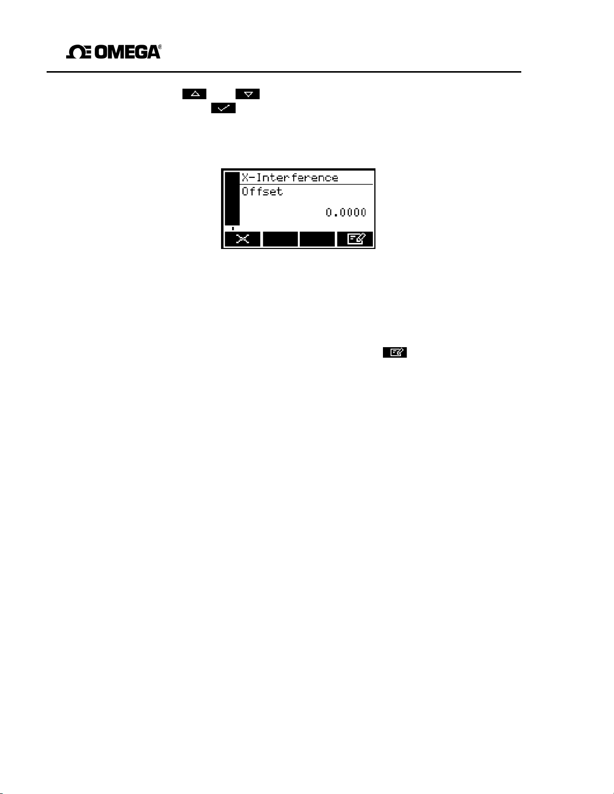
• The X- Interference offset screen is then displayed as shown in Figure 23.
the soft key:
Figure 23 - The X-Interference offset screen
4. The offset value shown on the X-Interference offset screen is the correction
which will be applied to oxygen sample
output).
If you want to change the offset value, press the soft key, then edit the
displayed offset as described in Section 4.10.
measurements
before they are displayed (or
41
Page 44

GAB-1700 Series Gas Analyzer
6.4 Configuring the measurement alarms
6.4.1 Alarm modes and levels
Two separate measurement alarms are available, which can be configured to operate in
one of three modes:
Alarm mode Operation
None The alarm is not used (that is, an alarm condition will
not be activated under any circumstances).
Low alarm An alarm condition will be activated when a sample
measurement is lower than the preset alarm level.
High alarm An alarm condition will be activated when a sample
measurement is higher than the preset alarm level.
While a measurement alarm condition is activated:
• An ‘alarm’ icon is shown on the measurement screen (see Section 4.2). The
number ("1" or "2") in the icon will identify the alarm which has been triggered.
• If the audible measurement alarm is enabled (see Section 6.4.5), the audible alarm
goes on.
• The alarm LED on the front of the GAB-1700 (see Figure 1) flashes on and off.
• You can view the details of the activated alarm: see Section 6.4.8.
6.4.2 Latching/non-latching alarms
You can configure each of the two measurement alarms to be either latching or not
latching:
Alarm setting Meaning
Latching Once the alarm condition has been activated, the
alarm condition remains activated (even if subsequent
sample measurements would not trigger the alarm) until
the alarm is manually unlatched: see Sect ion 6.4.7.
Not latching Once the alarm condition has been activated, the
alarm condition remains activated only until a
subsequent sample measurement which would not
trigger the alarm is made. The alarm condition is then
deactivated.
42
Page 45

GAB-1700 Benchtop Gas Analyzer
6.4.3 Hysteresis levels
The hysteresis level associated with a measurement alarm determines when an alarm
condition (once activated) is deactivated, and this depends on the alarm mode, as
follows:
Alarm mode Effect of hysteresis
Low alarm Once the low alarm condition has been activated, the alarm
condition will not be deactivated until a sample
measurement is above (alarm level + hysteresis level).
High alarm Once the high alarm condition has been activated, the alarm
condition will not be deactivated until a sample
measurement is below (alarm level - hysteresis level).
For example:
• If a ‘low’ alarm has an alarm level of 18% and a hysteresis level of 1%, the alarm will
be activated when a sample measurement is < 18%, and the alarm will not be
deactivated until a sample measurement is > 19%.
• If a ‘high’ alarm has an alarm level of 20% and a hysteresis level of 2%, the alarm will
be activated when a sample measurement is > 20%, and the alarm will not be
deactivated until a sample measurement is < 18%.
43
Page 46
GAB-1700 Series Gas Analyzer
6.4.4 Setting the measurement alarm levels and modes
☞ Ensure that the measurement alarm and hysteresis levels are not too close to
the expected sample measurements. (If they are, minor – and acceptable variations in your sample gas concentrations will result in spurious alarms.)
☞ If you configure one measurement alarm as ‘low’ and configure the other
alarm as ‘high’, ensure that the ‘high’ alarm and hysteresis levels are higher
than the ‘low’ alarm and hysteresis levels. (If you do not, the GAB-1700 can be
Before you start to take sample readings, you must ensure that the measurement
alarms are correctly configured for your sample gases.
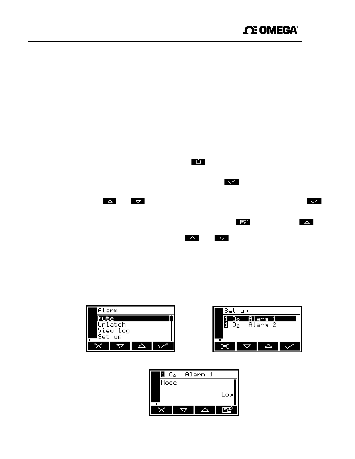
1. On the Measurement screen, press the soft key. The Alarm option screen will then
2. Highlight the "Set up" menu option, then press the soft key. The Alarm set up
3. Use the and soft keys to highlight t he required alarm, then press the
4. If the alarm mode is not the required mode, press the soft key, use the
5. On the Alarm mode screen, use the and soft keys to highlight each of
permanently in an alarm condition, until you correct the levels.)
be displayed, as shown in Figure 27.
screen will then be displayed, as shown in Figure 28.
soft key. The Alarm mode screen will then be displayed, as shown in Figure 29.
the following alarm options, and select the required option (using the method in
Step
4 above) or enter the appropriate levels (using the method described in
Section 4.10):
• Latching
• Level
• Hysteresis.
Figure 27 - The Alarm option
screen
Figure 28 - The Alarm set up
screen
Figure 29 - The Alarm mode
screen
44
Page 47
GAB-1700 Benchtop Gas Analyzer
6
.4.5 Enabling/disabling the audible measurement alarm
☞
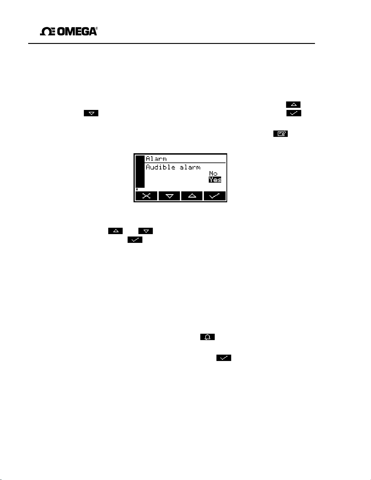
1. With the Alarms option screen displayed (see Section 6.4.4), use the and
2. If the displayed alarm setting is not the required setting, press the soft key.
The audible measurement alarm options are "Yes" (for enable) and "No" (for
disable).
soft keys to highlight the "Audible alarm" option, then press the soft
key.
The Audible alarm option screen will then be displayed: see Figure 30.
Figure 30 - The Audible alarm option screen
3. Use the and soft keys to select the required option ("Yes" or "No"),
then
press
the soft key.
6.5.6 Silencing (muting) the audible measurement alarm
☞
The audible alarm will only go on when a measurement is made which
triggers a measurement alarm condition and the audible measurement
alarm has been enabled (see Section 6.4.5).
When the audible alarm is on because of a measurement alarm condition, you can
temporarily silence (mute) the audible alarm, as follows:
1. On the Measurement screen, press the soft key; the Alarm option screen
(Figure 27) will then be displayed.
2. With the "Mute" option highlighted, press the soft key. The audible alarm will
then go off and the Measurement screen will be displayed again.
☞
Once silenced, the audible alarm will go on again:
• If the measurement alarm condition which caused the audible alarm to go
on is deactivated and is then re-activated.
• If a new measurement alarm condition is activated.
You will then need to silence the audible measurement alarm again.
45
Page 48
GAB-1700 Series Gas Analyzer
6.4.7 Unlatching measurement alarms
When necessary, use the following procedure to unlatch any ‘latched’ measurement
alarm(s) (see Section 6.4.2):
1. On the Measurement screen, press the soft key; the Alarm option screen
(Figure 27) will then be displayed.
2. With the "Unlatch" option highlighted, press the soft key. All latched alarms will
then be unlatched and the Measurement screen will be displayed again.
6.4.8 Viewing the measurement alarm status
1. On the Measurement screen, press the soft key; the Alarm option screen
(see Figure 27) will then be displayed.
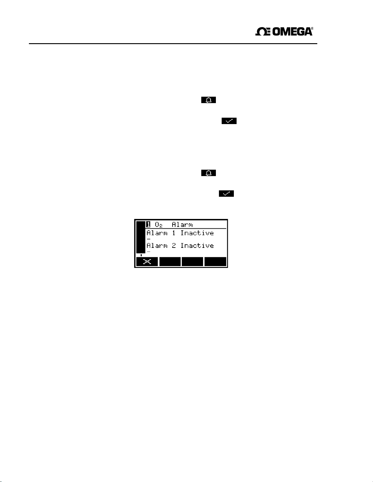
2. With the "View" option highlighted, press the soft key. The Alarm status
screen will then be displayed (see Figure 31).
Figure 31 - The Alarm status screen
In the Alarm status screen shown in Figure 31, both measurement alarms are shown as
"Inactive"; that is, either the mode of each alarm is set to ‘none’, or no alarm
condition currently exists.
If a measurement alarm condition exists when you view this screen, the screen will
show:
• The alarm number ("1" or "2").
• The sample reading which triggered the alarm condition.
• The alarm mode (where "<" indicates a low alarm and ">" indicates a high alarm).
• The alarm level.
46
Page 49

GAB-1700 Benchtop Gas Analyzer
6.5 Configuring and using the optional milliamp output
6.5.1 Overview
The GAB-1700 can be supplied with a milliamp output to provide a constantly updated
output (from the connector on the rear of the GAB-1700, see Figure 2), in which the
current represents the value of gas sample measurement.
The GAB-1700 allows you to specify two separate output configurations for the milliamp
output: Range 1 and Range 2. The Range with which a measurement is currently
associated is shown on the Measurement screen (see Figure 3):
is shown if Range 1 is selected.
is shown if Range 2 is selected.
The milliamp output provides one of the following selectable output current ranges, for
gas sample measurements:
• 0 to 20 mA, where 0 mA represents a sample measurement of 0 (zero) and 20 mA
represents a user selected highest sample measurement (the span).
• 4 to 20 mA, where 4 mA represents a sample measurement of 0 (zero) and 20 mA
represents a user selected highest sample measurement (the span).
In addition to the above, you can specify how the milliamp output wi ll operate during
calibration, during a fault condition, and during under-range conditions.
Details of the output parameters for the milliamp output are given in Section 6.5.2. Set
up, configure, check, calibrate and use the milliamp output as described in
Sections 6.5.3 to 6.5.6.
47
Page 50

GAB-1700 Series Gas Analyzer
6.5.2 Introduction to the milliamp output parameters
The milliamp output parameters that you must set up are as follows:
Parameter Values/options
Range 1 high level The Range 1 highest sample measurement (span) *.
Range 2 high level The Range 2 highest sample measurement (span) *.
During calibration The selected option determines how the milliamp output will
operate during calibration:
Freeze As soon as the calibration screen is displayed,
the milliamp output will ‘freeze’ at its last output
value. The output will only be updated to reflect
subsequent measurements when calibration has
been completed.
Follow The milliamp output value will reflect the
measurement value, even during calibration.
Jam condition The selected option determines how the milliamp output will
operate during a fault condition:
High The output value will be held at 21.5 mA.
Low The output value will be held at 0 mA.
None The output values will continue to be derived
from the sample gas measurements, even
though these output values may be err oneous.
mA output range 0-20 mA or 4-20 mA *, configurable as follows:
0-1% to 0-100% O
Under-range Any value below 4 mA
industrial oxygen sensor
2
#
* See Section 6.5.1.
# Only available if the 4-20 mA output range is selected; this sets the lowest out- put current
during normal operation, and allows negative gas concentrations to be monitored through
the milliamp outputs. For example, with an under- range setting of 3.8 mA, the milliamp
outputs can be less than 4 mA (which indicates a zero gas concentration), down to a
minimum of 3.8 mA, where an output between 3.8 mA and 4 mA indicates a negative gas
concentration.
48
Page 51
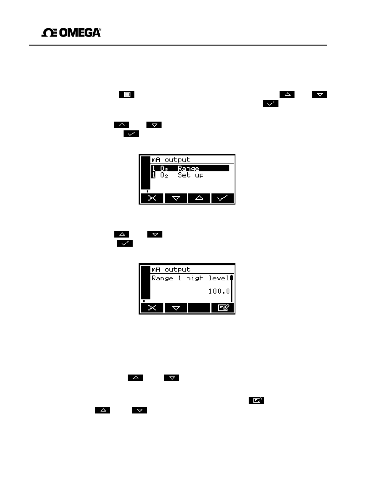
GAB-1700 Benchtop Gas Analyzer
6.5.3 Set up the milliamp output parameters
Use the following procedure to set up the milliamp output parameters:
1. Press the soft key to display the Menu screen, use the and soft
to
keys
screen will then be displayed (see Figure 17).
2. Use the and soft keys to highlight the "mA output" menu option, then
press the soft key: the mA configuration screen is then shown (see
Figure 32).
highlight the "Set up" menu option, then press the soft key. The Set up
Figure 32 - The mA configuration
screen
3. Use the and soft keys to highlight the required "Set up" option, then
press the soft key: the corresponding mA output high level screen will then be
shown: see Figure 33.
Figure 33 - The mA output high level
screen
4. If necessary, change the displayed parameter us ing the edit method described in
Section 4.10.
5. For each of the other milliamp parameters (see Section 6.5.2):
• Use the and soft keys to select the corresponding parameter
screen.
• Change the parameter as necessary: press the soft key then use
and
soft keys to select the required option, or edit the data as
described in Section 4.10.
the
☞
You cannot enter a high level (span) value higher than the maximum
measurement that the corresponding gas sensor can determine (refer
to Sections 2.5 to
2.8).
49
Page 52
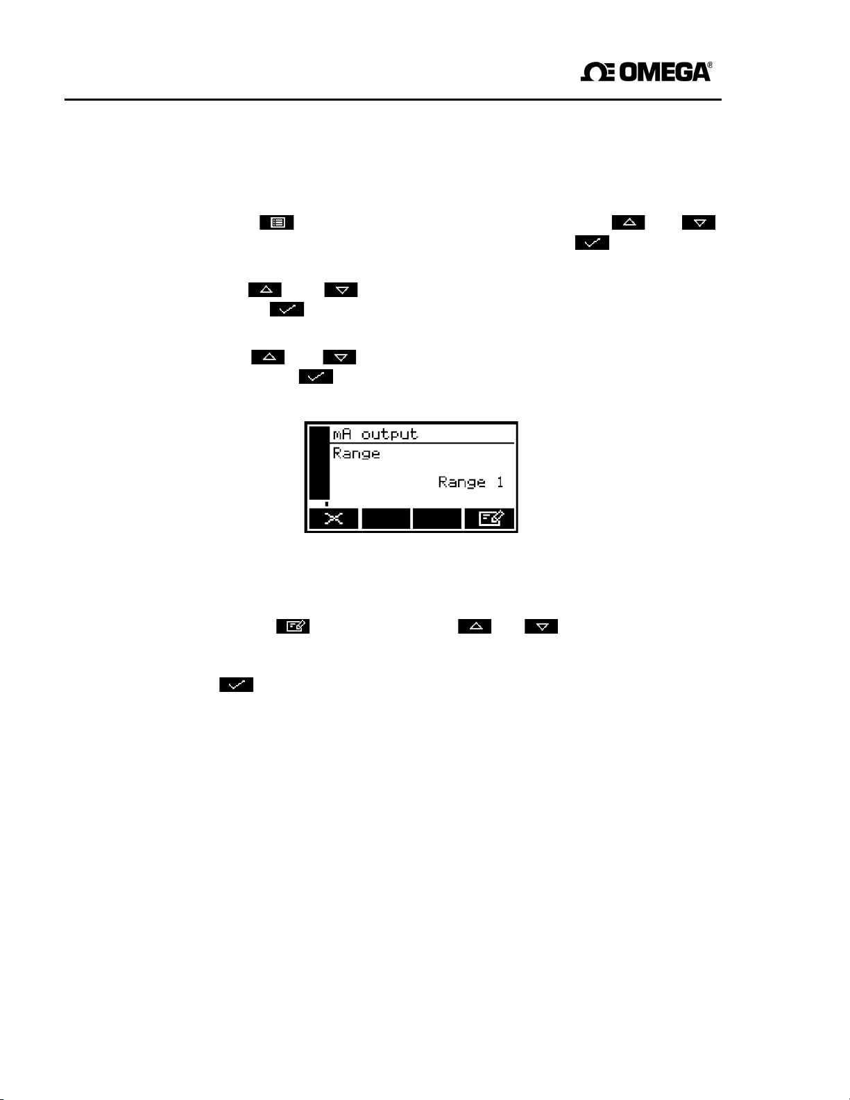
GAB-1700 Series Gas Analyzer
6.5.4 Select the Range associated with a measurement
Use the following procedure at any time during sampling to change the Range (see
Section 6.5.1) associated with a gas measurement:
1. Press the soft key to display the Menu screen, use the and soft
keys to highlight the "Set up" menu option, then press the soft key. The Set up
screen will then be displayed (see Figure 17).
2. Use the and soft keys to highlight the "mA output" menu option, then
press the soft key: the mA configuration screen is then shown (see
Figure 32).
3. Use the and soft keys to highlight the required gas Range option,
then press the soft key: the mA range screen will then be displayed, as
shown in Figure 34.
Figure 34 - The mA range screen
4. To change the selected Range:
• Press the soft key, then use the and soft keys to highlight the
alternative Range option (Range 1 or Range 2).
Press the soft key: the mA Range screen will then be displayed again, with the
new Range shown.
50
Page 53
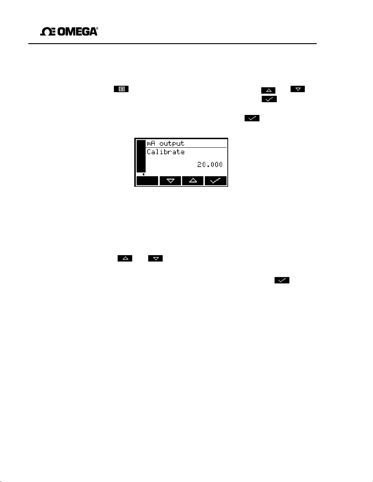
GAB-1700 Benchtop Gas Analyzer
Press the
soft key to display the Menu screen, use the
and
soft
keys to highlight the "Service" menu option, then press the
soft key. The
mA output service screen will then be displayed: see Figure 36.
6.5.5 Calibrate a milliamp output
Use the following procedure to calibrate a milliamp output:
1.
2. Select the required ‘Calibrate’ option, then press the soft key. The mA
output calibrate screen will then be displayed, as shown in Figure 35.
Figure 35 - The mA output calibrate screen
3. As soon as the mA output calibrate screen is shown, the nominal milliamp output
51
value is set to 20 mA:
• Use your equipment (connected to the milliamp connector on the rear of the
GAB-1700) to monitor the actual output value.
• Use the and soft keys to increase or decrease the actual output
value until your equipment indicates 20 mA output.
4. When the milliamp output has been correctly calibrated, press the soft key:
the mA output service screen (Figure 36) will then be displayed again.
☞
The actual milliamp output value is controlled from the mA output calibrate
screen as long as the screen is displayed. As soon as the mA service screen
is displayed, the milliamp output value will be updated to reflect the
corresponding gas measurement.
Page 54
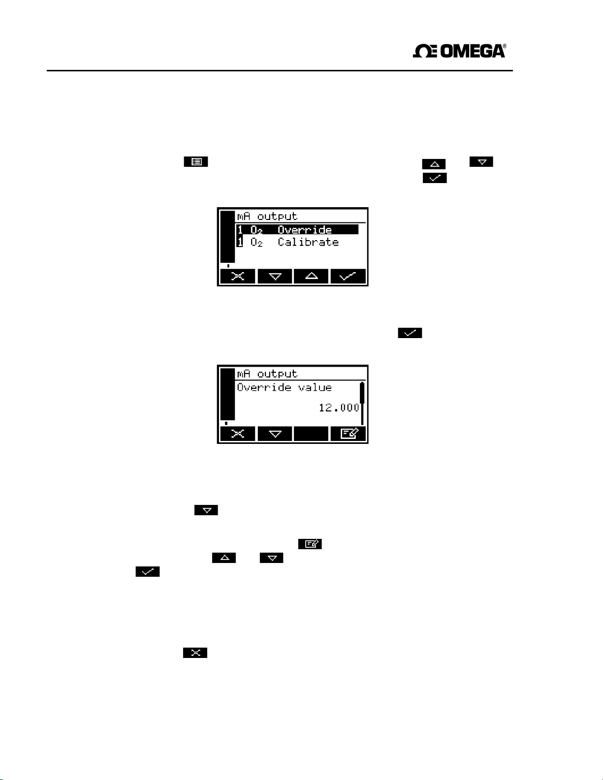
GAB-1700 Series Gas Analyzer
Press the
soft key to display the Menu screen, use the
and
soft
keys to highlight the "Service" menu option, then press the
soft key. The
mA output service screen will then be displayed: see Figure 36.
6.5.6 Check a milliamp output
If required, use the following procedure at any time to perform a check on a milliamp
output:
1.
Figure 36 - The mA output service screen
2. Select the required ‘Override’ option, then press the soft key. The mA
output override screen will then be displayed, as shown in Figure 37.
Figure 37 - The mA output override screen
3. Edit the displayed override value as described in Section 4.10.
4. Press the soft key: an acceptance screen showing "No" will then be
displayed.
5. To apply the override, press the soft key: an ‘Override’ screen will then be
shown. Use the and soft keys to highlight the "Yes" option, then press the
soft key.
The milliamp output will now be set to the override value you have selected. Use
your equipment (connected to the milliamp connector on the rear of the GAB-1700)
to check that the output is correct.
6. If required, repeat Steps 3 to 5 above to check for other milliamp output values, or
press the soft key to display the mA output service screen again.
☞
The milliamp output freezes at the override value as long as the ‘Override’
screen is displayed. As soon as another screen is displayed, the milliamp
output value will be updated to reflect the corresponding gas measurement.
52
Page 55
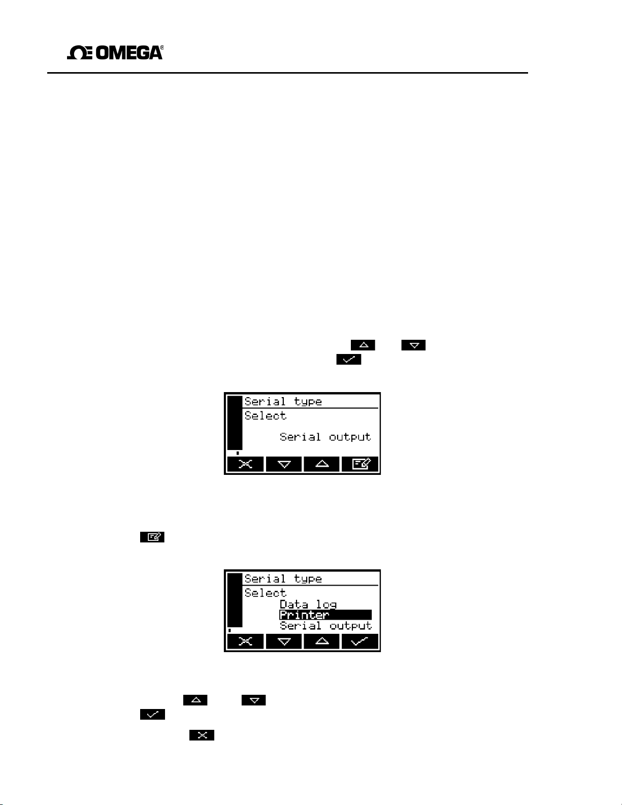
GAB-1700 Benchtop Gas Analyzer
6.6 Data logging, serial outputs and printed outputs
6.6.1 Selecting data logging/serial output/printed outputs
You can configure the GAB-1700 to provide data logging, to provide serial outputs, or to
provide a report to a printer.
• When serial output is selected, data is continuously output to your PC (or other
device) connected to the serial output port on the rear of the GAB-1700.
• When data logging is selected, measurement information is stored in GAB-1700 memory
(see Section 6.6.3). You must manually initiate output of the stored data log to a
connected device, as described in Section 6.6.6.
• When printer (printed output) is selected, you must manually initiate the printing of a
sample measurement report to the printer, as described in Section 6.6.9.
Use the following procedure to select the required option:
1. With the Menus screen displayed, use the and soft keys to highlight the
"Set up" menu option, then press the soft key. The Serial type screen will
then be displayed, as shown in Figure 38.
Figure 38 - The Serial type
screen
2. If the option shown on the Serial type screen is not the required option, press the
soft key; the Serial type select screen will then be displayed
Figure
39).
Figure 39 - The Serial type select
screen
3. Use the and soft keys to select the required option, then press the
key.
soft
4. Press the soft key to display the Menu screen.
53
(see
Page 56
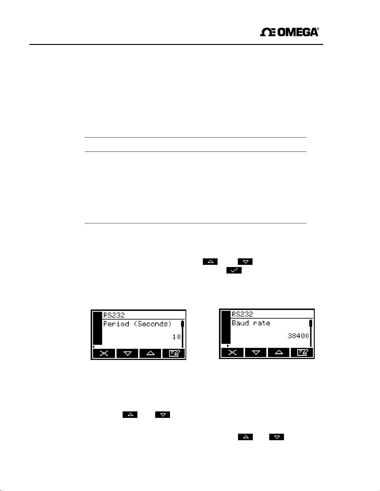
GAB-1700 Series Gas Analyzer
6.6.2 Configuring the serial output parameters
☞
The serial output parameters apply to both the data logging and serial output
options (see Section 6.6.1).
If you have selected data logging or serial outputs, you must configure the GAB-1700
serial output parameters to suit the requirements of the PC (or other device) which you
have connected to the serial output port on the rear of the GAB-1700.
parameters which you can configure are listed below:
The output
Parameter Valid settings
Period * 0 to 999 seconds.
Baud rate 2400, 4800, 9600, 19200 and 38400 are all supported.
Stop bits 1 or 2.
Data bits 7 or 8.
Parity None, odd parity, or even parity.
Time between updates: not applicable to data logging
*
.
To configure the parameters:
1. From the Settings screen, use the and soft keys to highlight the
"Serial output" menu option, then press the soft key. The first parameter
screen will then be displayed: if you have selected serial outputs, the RS232
period screen will be shown (see Figure 40); if you have selected data logging,
the RS232 baud rate screen will be shown (see Figure 41).
Figure 40 - The RS232 period screen Figure 41 - The RS232 baud rate screen
2. If necessary, change the displayed parameter using the edit method described in
Section 4.10.
3. For each of the other configurable parameters (see above):
• Use the and soft keys to select the corresponding parameter
screen.
• Change the parameter as necessary: use the and soft keys to
highlight the required option, or edit the data as described in Section 4.10.
54
Page 57
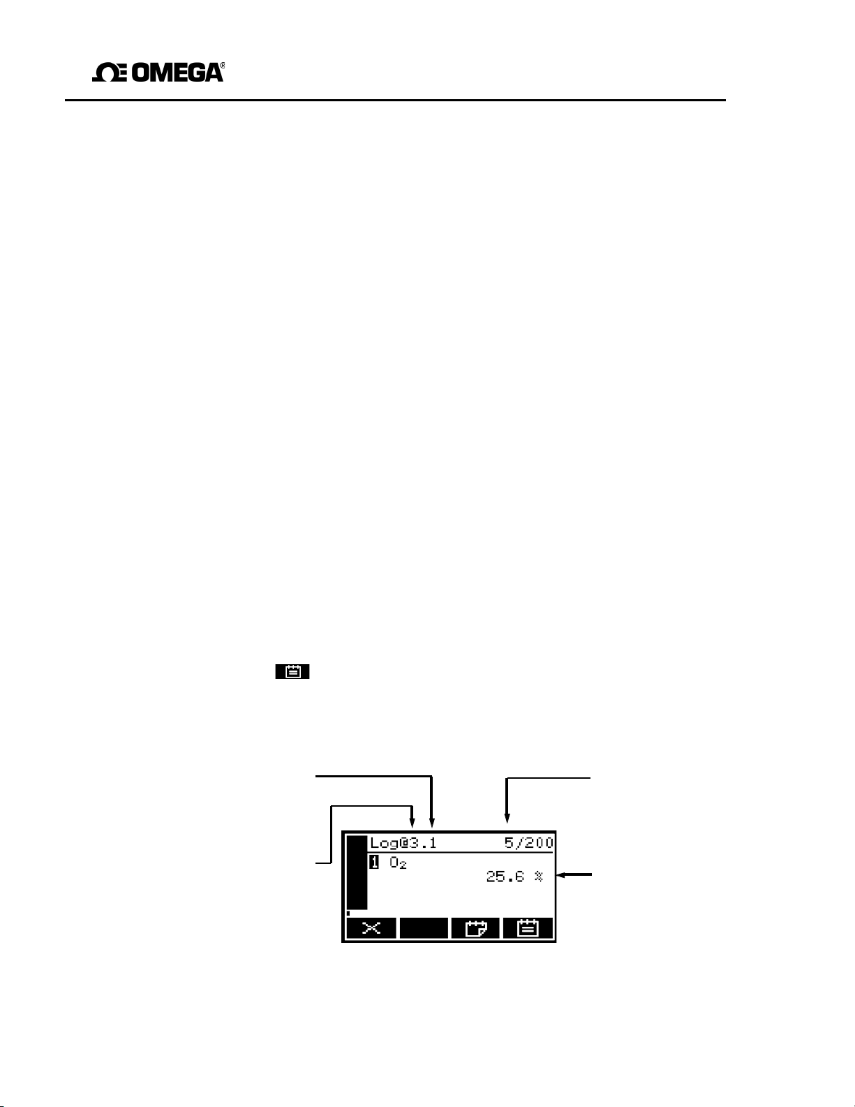
GAB-1700 Benchtop Gas Analyzer
Sequential number
Total number of
6.6.3 Introduction to data logging
The GAB-1700 allows you to maintain a data log of sample measurements made within
the internal memory. The data log consists of one or more ‘batches’ of measurements,
and a total of 200 measurements can be stored.
Each sample measurement entered in the log has:
• an associated batch number
• a sequence number of the sample measurement within the batch
• the date and time that the measurement was made
• an alarm indication (if the
measurement
caused a
measurement
alarm to be raised)
• a fault indication (if a fault existed at the time of the measurement).
You must manually transfer measurements into the data log, specify when a new batch
is to start within the data log, and clear the data log when necessary.
At any time, you can view the currently stored data log on the GAB-1700 display, or you
can output it to a device (such as a PC) connected to the GAB-1700 serial output port.
☞
The GAB-1700 cannot be configured to automatically log data over
specified periods of time. If you require such a facility, we recommend that
you select serial outputs (instead of data logging) and connect the serial
output to a PC or a data logger.
6.6.4 Entering measurement data into the data log
When you want to enter the sample measurement(s) from the Measurement screen into
the data log:
1. Press the soft key. When you press the soft key, the current sample
measurement at the time of the key press is ‘captured’ (stored in internal
memory), and the Data logging screen will then be displayed (see Figure 42).
55
of last measurement
in the current batch
Current batch number
Figure 42 - The Data logging screen
measurements
currently stored in
the data log
Captured sample
measurement
Page 58
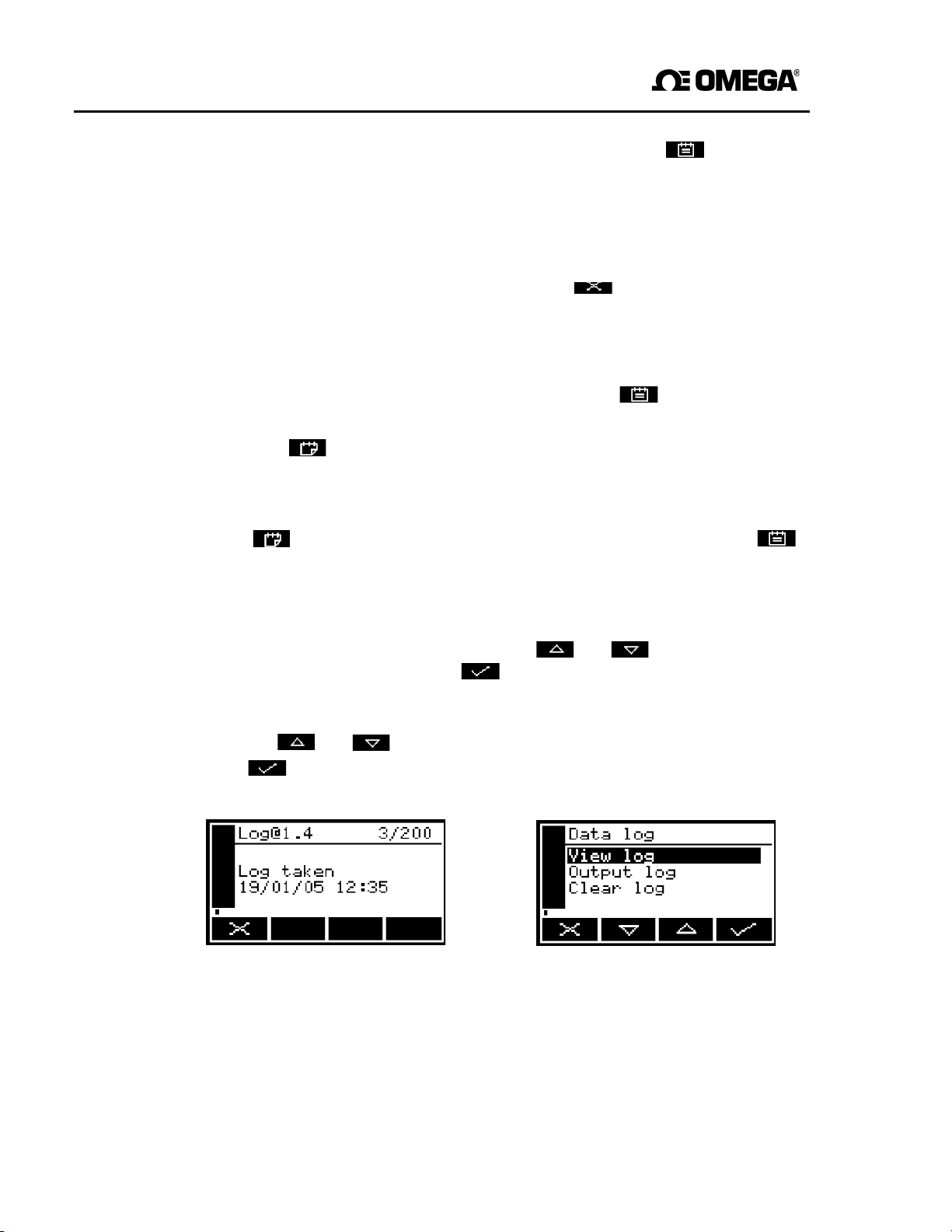
GAB-1700 Series Gas Analyzer
2.
Use the
and soft keys to highlight the "Output log" option, then press
the
soft key. The output of the data log will be initiated, and the
2. To store the measurement data in the data log, press the soft key.
A Log taken screen (Figure 43) is then displayed for a few seconds to verify that
the measurement data has been stored in the data log, then the Measurement
screen is shown again.
☞
6.6.5 Starting a new data log batch
To return to the Measurement screen without storing the captured sample
measurement data in the data log, press the soft key when the data
logging screen is displayed.
1. With the Measurement screen displayed, press the soft key. The Data
logging screen will then be displayed (see Figure 42).
2. Press the soft key. A new batch will then be started within the data log (and
the batch sequence number of the next measurement will be reset to "1").
☞
6.6.6 Outputting the data log
1. With the Menu screen displayed, use the and soft keys to highlight the
No new measurement data is entered into the data log when you press
the
soft key. To enter data into the new batch, you must press the
soft key again, or use the procedure given in Section 6.6.4.
"Data log" option, then press
be displayed, as shown in Figure 44.
the
soft key. The Data log
options
screen will then
Measurement screen will then be shown again.
Figure 43 - The Data log taken screen Figure 44 - The Data log options screen
☞
output parameters as described in Section 6.6.2.
56
The data log will only be output if you have correctly configured the serial
Page 59
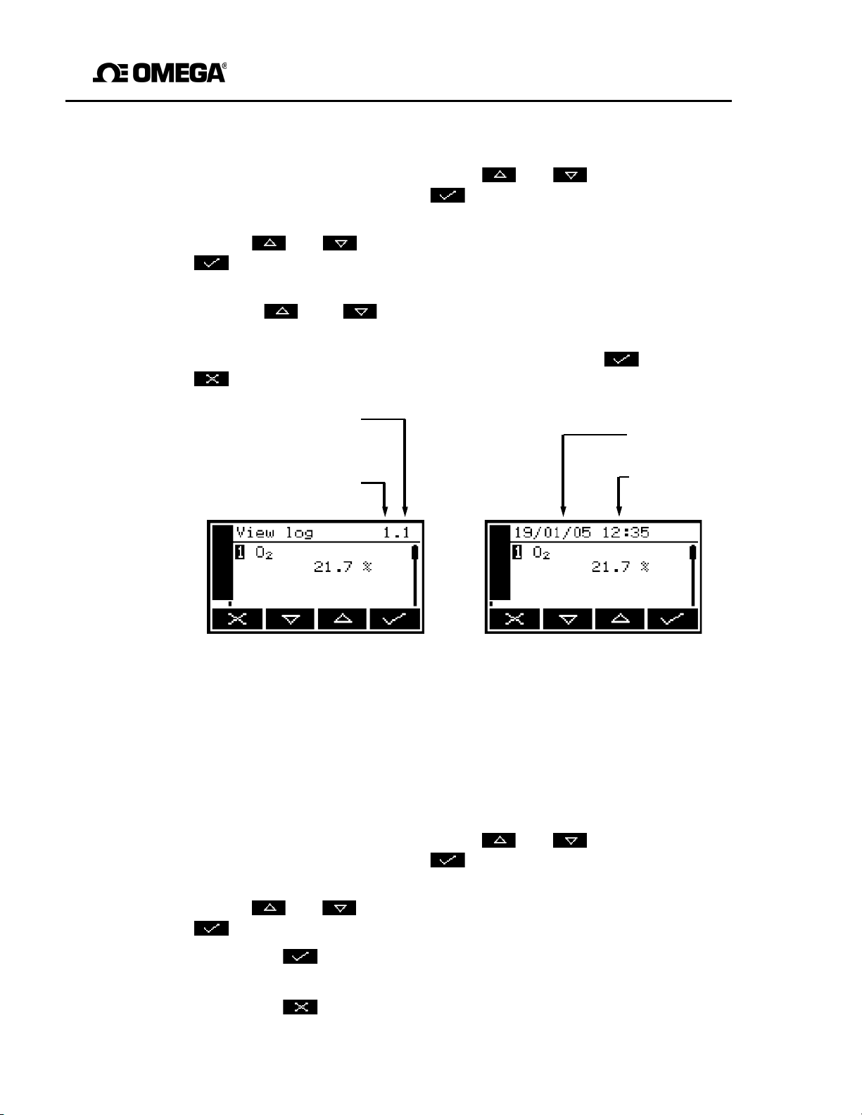
GAB-1700 Benchtop Gas Analyzer
Sequential number
Date of sample
6.6.7 Viewing the data log
1. With the Menu screen displayed, use the and soft keys to highlight the
"Data log" option, then press the soft key. The Data log options screen will
then be displayed, as shown in Figure 44.
2. Use the and soft keys to highlight the "View log" option, then press the
soft key. The View log (batch) screen is then displayed, alternating with the
View log (date) screen: see Figures 45 and 46.
3. Use the and soft keys to scroll through all of the measurements
stored in the data log.
4. When you have finished viewing the data log, press the soft key or the
soft key to display the Data log options screen again.
of measurement in
the batch
Batch number
measurement
Time of sample
measurement
Figure 45 - The View log
6.6.8 Clearing the data log
☞
Ensure that you have viewed the data log (see Section 6.6.7) or have output the
data log if required (see Section 6.6.6) before you clear the log.
☞
You cannot clear batches or individual measurements from the data log.
1. With the Menu screen displayed, use the and soft keys to highlight the
"Data log" option, then press the soft key. The Data log options screen will
then be displayed, as shown in Figure 44.
2. Use the and soft keys to highlight the "Clear log" option, t hen press the
soft key. The screen will then show an "Are you sure?" message:
• Press the soft key to clear the data log. The Data log options screen is
then displayed again.
(batch)screen
Figure 46 - The View log
(date)Screen
57
• Press the soft key to display the Data log options screen again without
clearing the data log.
Page 60
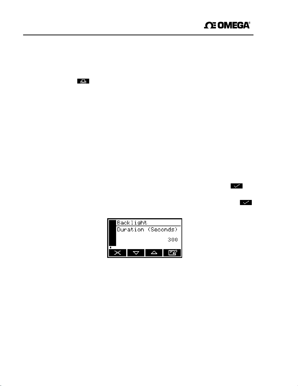
GAB-1700 Series Gas Analyzer
6.6.9 Printing a sample measurement report
If you have selected printed outputs (see Section 6.6.1), you must manually initiate the
printing of each sample measurement report.
Press the soft key when you want to print a report. Refer to Appendix A3 for the
format of the printed sample measurement report.
6.7 Adjusting the display
At any time, you can adjust the screen display to suit the ambient light conditions, as
described in Sections 6.7.1 and 6.7.2.
6.7.1 Adjusting the backlight timer
When the GAB-1700 is first switched on, the backlight goes on to illuminate the screen.
If no soft key is pressed, the backlight will remain on for the preset ‘back light time’, and
will then go off. The timer associated with the backlight time is restarted whenever a soft
key is pressed (that is, the backlight remains on for the backlight time after the last soft
key press). To adjust the backlight time:
1. On the Settings screen, highlight the "Backlight" option, then press the soft key.
The Backlight timer screen will then be displayed, as shown in Figure 47.
2. Change the backlight time (Duration) setting as required, then press the soft
key.
Figure 47 - The Backlight timer screen
☞
58
The backlight time (Duration) can be set between 0 and 999 seconds. Set the
backlight time (Duration) to 0 seconds to leave the backlight permanently
switched on.
Page 61
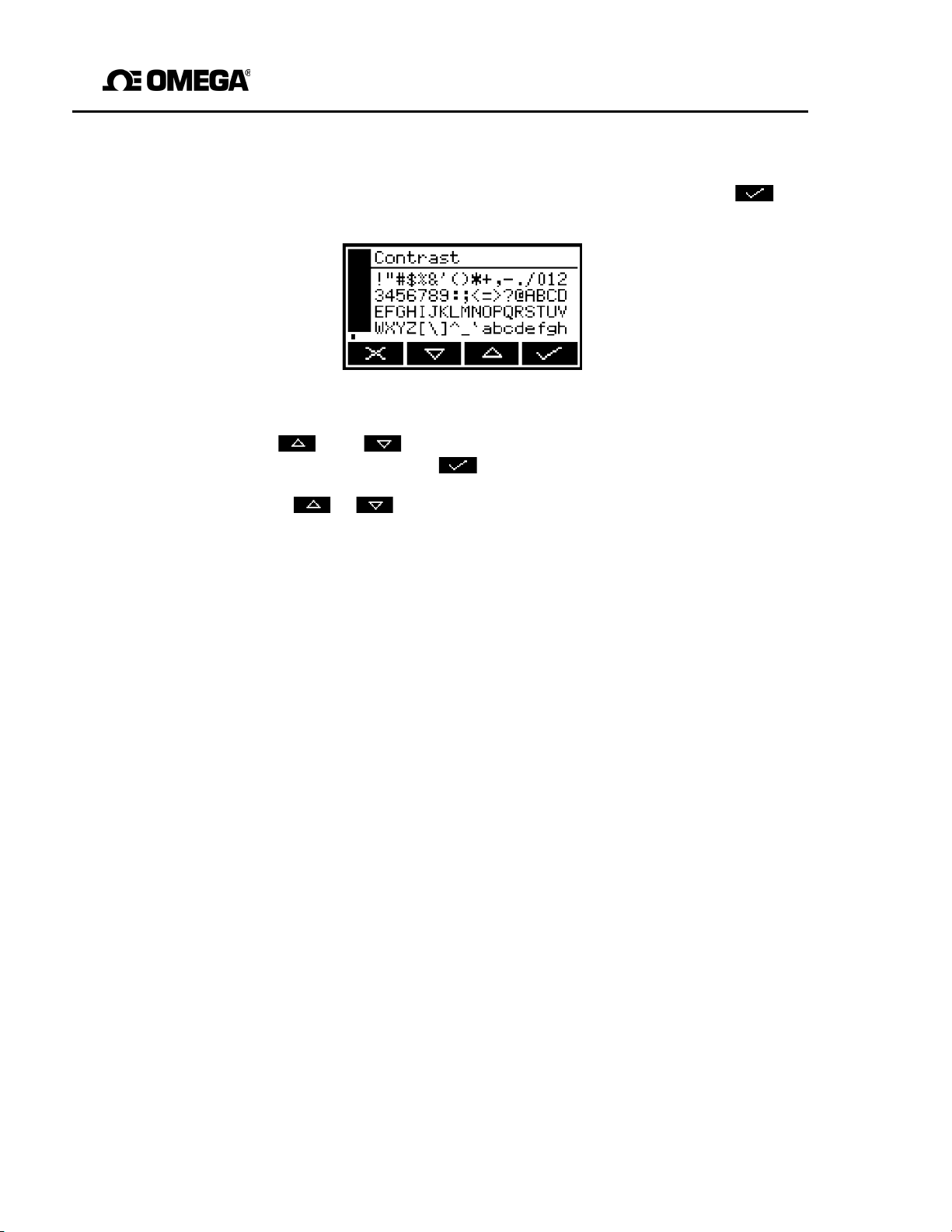
GAB-1700 Benchtop Gas Analyzer
6.7.2 Adjusting the contrast
1. On the Settings screen, highlight the "Contrast" option, then press the soft key.
The Contrast screen will then be displayed, as shown in Figure 48.
Figure 48 - The Contrast
2. Use the and soft keys to increase or decrease the contrast to the
required level, then press the soft key.
☞
Hold the or soft key pressed in to adjust the contrast quickly.
6.8 Switching off the GAB-1700 after use
When you have finished using the GAB-1700:
1. Switch off the GAB-1700: press and hold the Power On/Off key for approximately
2 seconds, then release the key when the audible alarm goes on.
2. If you will not use the GAB-1700 for several days:
Disconnect any tubes from the sample gas outlet and from the bypass gas
outlet (if fitted) on the rear of the GAB-1700 (see Figure 2).
Fit protective plastic caps to the sample gas outlet and the bypass gas outlet (if
fitted) on the rear of the GAB-1700 (see Figure 2), and to the sample gas inlet
on the front of the GAB-1700 (see Figure 1).
3. If required, disconnect the GAB-1700 from the electrical supply.
☞ If your GAB-1700 has the optional rechargeable battery, we recommend that
allow the battery to fully recharge before you disconnect the GAB-1700 from the
electrical supply
.
screen
you
☞ If your GAB-1700 has the optional rechargeable battery, you can leave the
GAB-
1700 connected to the electrical supply. This will not affect the service life of the
battery.
59
Page 62
GAB-1700 Series Gas Analyzer
7 ROUTINE MAINTENANCE
WARNING
Sample and calibration gases may be toxic or asphyxiant. Never
inlet filter, remove the side panels from the GAB-1700, or
the GAB-1700 while such gases are still connected to
service
WARNING
inspect
or repair
it.
Sample and calibration gases may be toxic or asphyxiant and may
within the GAB-1700 during use. Always inspect the inlet
GAB-1700, or remove the side panels from the
ventilated environment, so that such gases (if
hazard.
GAB-1700
present)
filter,
do not present a
WARNING
build
service the
in a well-
Sample and calibration gases may be toxic or asphyxiant. If you
there is a gross leak or internal pipework damage in the GAB-1700, leave
the GAB-1700 in a well-ventilated environment for at
7.1 Cleaning the GAB-1700
8 hours before servicing or
repair.
least
suspect
Regularly use a damp (but not wet) cloth to wipe clean the outer surfaces of the GAB1700, to prevent the entry of dust or other particulates into the gas sample inlet or the
7.2 Inspecting the inlet filter element
interior of the GAB-1700.
☞
The filter element is made of borosilicate glass, and the filter retainer cap
‘O’ ring is made from FKM (fluoroelastomer).
the
up
☞
New filter elements and filter retainer cap ‘O’ rings are available as spares.
If you only use the GAB-1700 on applications which use clean, dry cylinder gases, you
will only need to inspect the inlet filter element every 3 months. On other applications,
we recommend that you inspect the inlet filter element more frequently.
1. Ensure that the GAB-1700 is switched off.
2. Unscrew and remove the filter retainer cap (see Figure 1).
60
Page 63
GAB-1700 Benchtop Gas Analyzer
3. Inspect the condition of the white filter element (fitted to the spigot on the rear of the
filter retainer cap). If the filter element is wet or dirty:
• Remove the used filter element from the filter retainer cap, then dispose of the
element.
• Push a new filter element onto the spigot on the inner side of the filter retainer
cap.
4. Inspect the ‘O’ ring on the inner side of the filter retainer cap. If the ‘O’ ring is
twisted or damaged:
• Remove the ‘O’ ring, then dispose of it.
• Fit a new ‘O’ ring to the inner side the filter retainer cap.
5. Ensure that the ‘O’ ring is correctly located in the recess in the inner side of the filter
retainer cap, then refit and tighten the filter retainer cap.
CAUTION
Do not operate the GAB-1700 with the filter element removed.
particulates in the sample gas will seriously damage the
7.3 Regenerate/replace the drying agent
A GAB-1700 is supplied with a flexible drying tube, containing an indicating silica gel
drying agent.
You must regenerate or replace the drying agent when it has changed color from orange
to green: if required, use the procedure given in Section A6 to regenerate the drying
agent. Af ter regeneration or replacement of the dr ying agent, take care when you refit
the barbed connections on the drying tube, to ensure that they are securely fitted.
The recommended granule size for the indicating silica gel drying agent is 0.5-1.0 mm.
If
you do,
GAB-1700.
61
Page 64
GAB-1700 Series Gas Analyzer
7.4 Use of the GAB-1700 for toxic gas measurements
WARNING
If you sample toxic gases you
associated equipment. If
analyzer or associated
When you carry out a leak test, do not exceed a
gauge (5 psig, 0.35 bar gauge) and do not introduce a sudden change
pressure into the GAB-1700. If you do, you can damage
If you use the GAB-1700 for toxic gas sample measurements, you must reg ularly leaktest the GAB-1700 and the associated sample/vent lines or system.
We recommend that you leak-test the GAB-1700 at least once every 6 months:
must
leaks
are found, do not continue to use the
equipment
CAUTION
regularly leak test the GAB-1700 and
• If there are leaks within the GAB-1700, do not continue to use the analyzer.
• You must seal any leaks in your sample/vent lines or system.
until the leaks have been
maximum
pressure of 34.5
it.
sealed.
kPa
of
When you leak test, ensure that you do not exceed the maximum pressure, and do not
increase the pressure in the GAB-1700 too quickly (see the caution above): we
recommend that you allow at least 30 seconds to fully pressurize the GAB-1700 to
the maximum pressure.
62
Page 65

GAB-1700 Benchtop Gas Analyzer
7.5 Preventative maintenance
To minimize unscheduled GAB-1700 downtime, to ensure the proper operation of the
GAB-1700, and to comply with the guidelines of applicable regulatory bodies, we
recommend that you utilize an annual preventative maintenance program for your GAB-
1700.
The preventative maintenance program consists of a yearly inspection of the GAB-1700
at the Omega service facility, and repair of any faults, to ensure that the GAB-1700 meets
its original factory specification. Once inspection and repair are complete, the GAB-1700
is returned, together with a dated service certificate.
63
Page 66

GAB-1700 Series Gas Analyzer
8 FAULT FINDING
8.1 Introduction to faults and fault messages
When the GAB-1700 internal self-test facilities detect a fault:
• The audible alarm emits a single short tone.
• The amber fault LED (see Figure 1) goes on.
• A fault icon is shown on the measurement screen (see Figure 3).
• An appropriate fault message is stored.
You can view the current faults as described in Section 8.2. The fault messages which
can be shown - together with the recommended actions you should take - are listed (in
alphabetical order) in the table below:
Fault message Recommended actions
Battery fault This message will only be shown on a GAB-1700 which
has the optional rechargeable battery fitted.
Disconnect the power supply unit plug from the electrical
supply outlet, wait 30 seconds, then reconnect the plug to
the electrical supply outlet. If the fault persists, contact
Omega for assistance.
Calibration fault Recalibrate (both low and high) as described in Section 6.1.
If the fault persists, contact Omega for assistance.
Charging Timeout This message will only be shown on a GAB-1700 which
has the optional rechargeable battery fitted.
Check that the ambient temperature is in the correct range
for charging (see Section 2.4), and try to charge the battery
again. If the fault persists, contact Omega.
Code fault Contact Omega for assistance.
Communication fail Turn the GAB-1700 off, and then turn it on again. If the fault
message is then displayed again, contact Omega for
assistance.
Database fault Contact Omega for assistance.
Fault messages (Sheet 1 of 3)
64
Page 67

GAB-1700 Benchtop Gas Analyzer
Fault message Recommended actions
Date/Time invalid This usually occurs because a GAB-1700 without the opt ional
Fatal fault Contact Omega for assistance.
mA fault This fault message will only be shown on a GAB-1700 with the
mA not detected This fault message will only be shown on a GAB-1700 which
mA reset This fault message will only be shown on a GAB-1700 which
Power Config fault Contact Omega for assistance.
rechargeable battery has been left disconnected from the
electrical supply for more than a week. On a GAB-1700
with the optional rechargeable battery, this may occur when
the battery is fully discharged.
Connect the GAB-1700 to the electrical supply, then set the
date/time as described in Section 5.3.2. If the fault
persists, contact Omega for assistance.
optional milliamp output.
Ensure that the electrical cabling connected to the
GAB-1700 is not open
circuit.
Turn the GAB-1700 off, and then turn it on again. If the
fault persists, contact Omega for assistance.
has the optional milliamp output.
Contact Omega for assistance.
has the optional milliamp output.
Contact Omega for assistance.
Fault messages (Sheet 2 of 3)
65
Page 68

GAB-1700 Series Gas Analyzer
Fault message Recommended actions
Pump fault This fault message will only be shown on a GAB-1700 with an
internal sample pump.
Check that the sample gas inlet (see Figure 1) and the
sample gas outlet and bypass gas outlet (see Figure 2) are
not blocked or obstructed, and that any pipes or tubes
connected to the inlet and outlets are not blocked or
Static RAM f ault Turn the GAB-1700 off, and then turn it on again. If the fault
Transducer error Ensure that you are using the GAB-1700 in the specified
Tx incorrect type Contact Omega for assistance.
Tx Maintenance Check that the sample gas concentration is not higher than
Tx not detected Contact Omega for assistance.
obstructed.
After checking the inlet, outlets and pipes/tubes, restart the
sample pump (see Section 5.3.6). If the fault persists, contact
Omega for assistance.
message is then displayed again, contact Omega for
assistance.
operating conditions (refer to Section 2). If the fault persists,
contact Omega for assistance.
the transducer Full Scale Range.
Recalibrate (both low and high) as described in Section 6.1.
If this does not clear the fault, turn the GAB-1700 off, and
then turn it on again. If the f ault message is then displayed
again, contact Omega for assistance.
Fault messages (Sheet 3 of 3)
66
Page 69
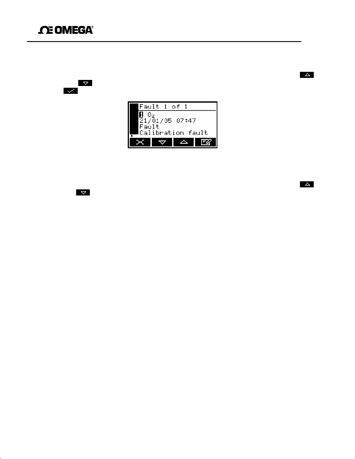
GAB-1700 Benchtop Gas Analyzer
8.2 Viewing fault messages
If you want to view details of faults currently detected by the GAB-1700, use the
and soft keys to highlight the "Faults" option on the Menu screen, then press the
soft key. The Fault status screen will then be displayed as shown in Figure 49.
If there is more than one currently detected fault, this will be indicated by the screen
heading and by the scroll bar at the right of the screen. If required you can use the
and soft keys to scroll through and view all of the current faults.
Each fault status screen shows:
• Date and time of fault
• Fault indicator
• Fault message.
Refer to Section 8.1 for the recommended actions associated with the displayed fault
messages.
8.3 General fault finding
For general GAB-1700 fault finding, refer to the table on the following pages.
If you have read through the table and still cannot rectify a fault, or cannot identify the
cause of a fault, contact Omega for assistance.
Figure 49 - The Fault status screen
67
Page 70

GAB-1700 Series Gas Analyzer
or
carried
a
and
knocked,
tion
s,
is
tion,
in
arget
Fault symptom Recommended actions
The Fault LED is on. Check any current fault messages (see Section
8.2), and carry out the recommended actions (see
Section 8.1).
If there are no applicable fault messages stored,
if you cannot rectify the fault after you have
out the recommended actions:
• Switch off the GAB-1700, then switch it on
again.
• If the fault persists, contact Omega for
assistance.
The software health indicator is not
moving on the display.
"- - - - - " is displayed instead of a
sample measurement (or appears in
the data log).
Carry out the recommended actions for the "The
Fault LED is on" symptom above.
This indicates a possible measurement error, or
communications error between a transducer
the GAB-1700 controller.
Check that the GAB-1700 is not being
moved, or subjected to high levels of vibra
during sample measurements. If the fault persist
contact Omega for assistance.
" " is displayed instead of
a sample measurement (or appears
the data
in
log).
This indicates that the sample gas measurement
above the upper measurement limit of the GAB-
1700.
If this is displayed or appears during calibra
check that the calibration gas is as specified
Section 2.3 and recalibrate the GAB-1700.
If this is displayed or appears during sample
measurement, check that the sample gas t
range is within the specification of the GAB-1700
(see Section 2.2).
68
General fault finding (Sheet 1 of 5)
Page 71

GAB-1700 Benchtop Gas Analyzer
is
ion,
in
arget
and
ss gas
pipes
if
pressure is
the
Check that any cross-interference offsets that you
Fault symptom Recommended actions
" " is displayed instead of
a sample measurement (or appears
the data
in
log).
This indicates that the sample gas measurement
below the lower measurement limit of the GAB-
1700.
If this is displayed or appears during calibrat
check that the calibration gas is as specified
Section 2.3 and recalibrate the GAB-1700.
If this is displayed or appears during sample
measurement, check that the sample gas t
range is within the specif ication of the GAB-1700
(see Section 2.2).
GAB-1700 response is slow. Check that the sample gas inlet is not blocked,
that the sample gas supply to the GAB-1700 is not
restricted.
Check that the sample gas outlet and bypa
outlet are not blocked, and that any tubes or
connected to the outlets are not restricted.
Inspect the inlet filter element and replace it
necessary: refer to Section 7.2.
GAB-1700 measurements are not
as expected.
General fault finding (Sheet 2 of 5)
Check that the sample gas supply
correct: refer to Section 2.2.
Check that the GAB-1700 is being used in
correct ambient conditions: refer to Section 2.4.
have entered are correct (see Section 6.3.2).
69
Page 72

GAB-1700 Series Gas Analyzer
pressure is
and
ass gas
bes
if
tion
and
ass gas
if
Fault symptom Recommended actions
GAB-1700 measurements are
unstable.
Check that the sample gas supply
correct: refer to Section 2.2.
Check that the GAB-1700 is not being subjected
to high levels of vibration.
Check that the sample gas inlet is not blocked,
that the sample gas supply to the GAB-1700 is not
restricted.
Check that the sample gas outlet and byp
outlet (if fitted) are not blocked, and that any tu
or pipes connected to the outlets are not restricted.
Inspect the filter element and replace it
necessary: refer to Section 7.2.
The GAB-1700 will not calibrate. Check that the correct low and high calibra
gases are being used: refer to Section 2.3.
Check that the sample gas inlet is not blocked,
that the sample gas supply to the GAB-1700 is not
restricted.
Check that the sample gas outlet and byp
outlet (if fitted) are not blocked. On a GAB1700 with an internal s ample pump, ch eck that the
calibration ‘T’ piece is not blocked. Check that
any tubes or pipes connected to the outlets (or
to the calibration ‘T’ piece) are not restricted.
Inspect the filter element and replace it
necessary: refer to Section 7.2.
70
General fault finding (Sheet 3 of 5)
Page 73

GAB-1700 Benchtop Gas Analyzer
ly
ly
for
ly
and
ect:
If
of
to
rnal
and the correct fuse is
nal
is
the
the
(refer
Check that the ambient temperature is within the
nge:
tment has
has
knocked,
tion
and
to
Fault symptom Recommended actions
The GAB-1700 will not switch on. If the green light on the power supply unit is on:
• Check that the power supply is correct
connected to the GAB-1700: see Section 5.1.
• If the power supply is already correct
connected to the GAB-1700, contact Omega
assistance.
If the green light on the power supply unit is off:
• Check that the power supply unit is correct
connected to your electrical supply outlet,
that your external electrical supply is corr
see Section 2.1.
• Check the fuse in the power supply unit plug.
the fuse has failed, replace it with a new fuse
the correct rating.
The GAB-1700 display is blank or is
too dark.
The measurement alarms are
activating more often than expected.
71
General fault finding (Sheet 4 of 5)
• If the power supply unit is correctly connected
your electrical supply outlet, your exte
electrical supply is correct
fitted, then the power supply unit may have
failed: contact Omega for assistance.
If you have a GAB-1700 with the optio
rechargeable battery, and the power supply unit
not connected to the electrical supply and to
GAB-1700, the battery may be flat: connect
power supply unit and recharge the battery
to Section 5.2).
valid GAB-1700 operating temperature ra
refer to Section 2.4.
Check that the display contrast adjus
been correctly set (refer to Section 6.7.2), and
not been altered.
Check that the GAB-1700 is not being
moved, or subjected to high levels of vibra
during sample measurements.
Check that the alarm modes, alarm levels
hysteresis levels have been correctly set: refer
Section 6.4.4.
Page 74

GAB-1700 Series Gas Analyzer
led,
to
led,
correctly
refer to
PC
rial
may
to
jam
condition
tact
Fault symptom Recommended actions
The GAB-1700 does not
communicate correctly through the
serial output connector.
Check that the update rate has been correctly set.
Check whether data logging has been enab
and disable data logging if necessary (refer
Section 6.6.1). (If data logging is enab
continuous serial data outputs will be disabled.)
Check that the GAB-1700 serial output parameters
have been correctly set for the system to which
you have connected the serial outputs (refer to
Section 6.6.2).
Check that the external device is
connected to the GAB-1700 serial port:
Appendix A4.
If you have connected the serial outputs to a
(Personal Computer), check that the correct se
port is selected on the PC. (Note that you
have to restart the PC for serial port changes
take effect.)
A milliamp output is at 0 or 21.5 A. If you have configured the milliamp output to
high or jam low, check whether a fault
exists (see Section 6.5.3). Otherwise, con
Omega for assistance.
A milliamp output is not as
expected.
Ensure that the electrical cabling connected to the
GAB-1700 is not open circuit.
Check that the milliamp output is calibrated
correctly (see Section 6.5.5).
Check that you have selected the correct Range
(see Section 6.5.1).
72
General fault finding (Sheet 5 of 5)
Page 75

GAB-1700 Benchtop Gas Analyzer
9 STORAGE AND DISPOSAL
9.1 Storage
Refit any protective plastic covers (see Section 3) and place the GAB-1700 and any
associated equipment in its original packaging before storage. Alternatively, seal it inside
a waterproof plastic bag, sack, or storage box.
Store the GAB-1700 and any associated equipment in a clean, dry area. Do not subject
it to excessively hot, cold, or humid conditions: see Section 2.4.
☞
If your GAB-1700 has an optional rechargeable battery, recharge the
battery every 2 months: see Section 5.2.
9.2 Disposal
Dispose of the GAB-1700, the power supply unit and any other associated
equipment safely, and in accordance with all of your local and national safety and
environmental requirements.
☞ The GAB-1700 is not suitable for disposal in municipal waste streams
(such as landfill sites, domestic recycling centers and so on). Refer to
Appendix A7 for disposal requirements in accordance with the WEEE
Directive within the EC.
☞
If you send the GAB-1700 to Omega for disposal, the analyzer must be
accompanied by a correctly completed decontamination certificate.
73
Page 76

GAB-1700 Series Gas Analyzer
APPENDIX
A1 DATA LOG OUTPUT FORMATS
The data log is output in the form of an identifier line, followed by a number of log lines, one
line for each entry stored in the data log.
The identifier line is in the form: "<serial number> ; <gas>", where <serial number> is the
GAB-1700 serial number as shown on the Information screen (see Figure 7) and <gas> is
as specified below.
Each log line consists of a number of elements, separated from each other by the
delimiter string " ; " (space, semicolon, space), in the following format:
<log
id> ;
<date> ; <time> ; <gas> ; <measurement> ; <units> ; <alarm status> ; <fault
<gas> ; <measurement> ; <units> ; <alarm status> ; <fault
status>]
status> [
where:
<log id> Is in the form "X.Y", where "X" is a digit (or digits) specifying]
the batch number and "Y" is a digit (or digits) specifying the
number of the measurement within the batch.
<date> Is the date on which the data log entry was made.
<time> Is the time at which the data log entry was made.
<gas> Specifies the sample gas measured.
<measurement> Is the actual sample measurement as displayed on the
measurement screen.
<units> Is the measurement units, as displayed on the measurement
screen.
<alarm status> Is either blank (not output), or "Alarm" if a measurement
alarm condition existed when the log entry was made.
<fault status> Is either blank (not output), or "Fault" if a fault condition
existed when the log entry was made.
"[" and "] " Elements between these bracket symbols are only output
when the GAB-1700 is configured for two sample
measurements. The bracket symbols themselves do not appear
in the output.
74
;
Page 77

GAB-1700 Benchtop Gas Analyzer
A typical extract from a GAB-1700 data log output is shown below:
05250A1/45678 ; O2
1.1 ; 19/01/05 ; 14:57:04 ; O2 ; 14.8 ; % ; Alarm ;
1.2 ; 19/01/05 ; 14:57:09 ; O2 ; 14.8 ; % ; Alarm ;
1.3 ; 19/01/05 ; 14:57:16 ; O2 ; 14.8 ; % ; Alarm ; Fault
2.1 ; 19/01/05 ; 14:57:36 ; O2 ; 14.8 ; % ; Alarm ;
2.2 ; 19/01/05 ; 14:57:42 ; O2 ; 14.8 ; % ; Alarm ;
2.3 ; 19/01/05 ; 14:57:58 ; O2 ; 14.8 ; % ; Alarm ; Fault
3.1 ; 19/01/05 ; 14:58:13 ; O2 ; 14.8 ; % ; Alarm ;
3.2 ; 19/01/05 ; 14:58:46 ; O2 ; 20.5 ; % ; ;
3.3 ; 19/01/05 ; 14:58:51 ; O2 ; 20.5 ; % ; ;
3.4 ; 19/01/05 ; 14:58:55 ; O2 ; 20.5 ; % ; ; Fault
4.1 ; 19/01/05 ; 14:59:03 ; O2 ; 20.5 ; % ; ; Fault
4.2 ; 19/01/05 ; 14:59:08 ; O2 ; 20.5 ; % ; ;
75
Page 78

GAB-1700 Series Gas Analyzer
A2 SERIAL OUTPUT FORMATS
The serial output consists of a number of
measurement
lines, one line for each update.
Each measurement line consists of a number of elements, separated from each other
by the delimiter string " ; " (space, semicolon, space), in the following format:
<date> ; <time> ; <gas> ; <measurement> ; <units>[ ; <gas> ; <measurement> ; <units>]
where:
<date> Is the date on which the data log entry was made.
<time> Is the time at which the data log entry was made.
<gas> Specifies the sample gas measured.
<measurement> Is an actual sample measurement, as displayed on the
measurement screen.
<units> Is the measurement units, as displayed on the
measurement screen.
"[" and "]" Elements between these bracket symbols are only output
when the GAB-1700 is configured for two sample
measurements. The bracket symbols themselves do not
appear in the output.
An extract from a typical serial output is shown below:
19/01/05 ; 14:50:25 ; O2 ; 20.3 ; %
19/01/05 ; 14:50:35 ; O2 ; 20.3 ; %
19/01/05 ; 14:50:45 ; O2 ; 20.3 ; %
19/01/05 ; 14:50:55 ; O2 ; 20.3 ; %
19/01/05 ; 14:51:05 ; O2 ; 20.3 ; %
☞
Alarms and fault information are not provided in the serial outputs.
76
Page 79

GAB-1700 Benchtop Gas Analyzer
A3 PRINTER OUTPUT FORMATS
If you have selected printed outputs (see Section 6.6.1), each time you press the
soft key, a single sample measurement report is printed. The format of this report is as
shown below:
Date:
<date>
Time:
I.D.:
<time>
<serial number>
Batch:
Product:
Measurement:
1 <gas>
XXXX <units>
<alarm>
Signature
where:
<date> Is the date on which the report was printed, in the currently
selected format (see Section 5.3.2).
<time> Is the time at which the report was printed, in the format
hh:mm:ss (hours:minutes:seconds).
<serial number> Is the serial number of the GAB-1700.
1 <gas> Specifies transducer 1 and the sample gas measured.
XXXX Is the sample measurement.
<units> Is the measurement units, as displayed on the measurement
<alarm> Specifies the alarm or other status:
77
screen.
• "PASS" indicates that alarms have been configured, and
that the sample measurement has not triggered an alarm.
• "FAIL" indicates that alarms have been configured, and that
the sample measurement has triggered an alarm.
Page 80

GAB-1700 Series Gas Analyzer
Batch and Are fields which you can complete (by hand) to identify, for example,
Product a specific batch, and a specific product within that batch.
Signature Is a field which can be used for the signature of the person
☞
Refer to your company procedures for the correct usage of the Batch,
Product and Signature fields of printed sample measurement reports.
☞
Refer to the printer manual for additional information (for example, on how to
replace the printer roll).
• "FAULT" indicates that a transducer fault is present.
• "RECALIB" indicates that the transducer needs to be
recalibrated. (This will be shown when the sample
measurement is >100% or < 0% and no alarms have been
configured.)
If no alarms have been configured (and no transducer or
recalibration fault is present), <alarm> will be blank.
who printed the report.
78
Page 81
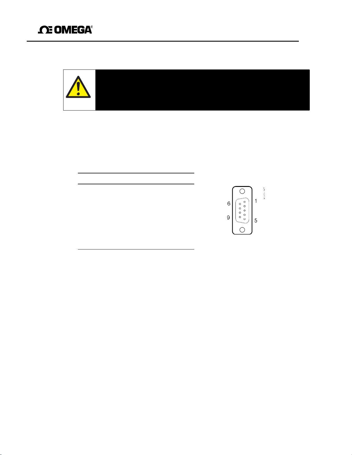
GAB-1700 Benchtop Gas Analyzer
A4 RS232 CONNECTION DETAILS
Ensure that the electrical installation of any equipment connected to
GAB-1700 conforms with all applicable local and national
A4.1 Overview
The serial port on the rear of the GAB-1700 (see Figure 2) is an RS232 ± 5.5 V
9-way ‘D’ type connector.
The pins on the connector are used as shown in Figure A1 below:
Pin(s)
1 Not used
2 Rx (to GAB-1700)
3 Tx (from GAB-1700)
4 Not used
5 0 V
6, 7, 8, 9 Not
Use
used
Figure A1 - RS232 connection pin details
A4.2 Connecting the GAB-1700 to a PC
The GAB-1700 can be directly connected to the 9-way ‘D’ type serial port (usually
designated "COM1" or "COM2") on your PC. To comply with EMC immunity standards,
we recommend that you use the serial output cable supplied. If you do not use the cable
supplied, use a compatible 9-way ‘D Null Modem’ cable (with a recommended
maximum length of 3 m), with female-to-female connectors.
If your PC only has USB serial ports, use a
USB converter to connect the GAB-1700 to one of the serial ports.
WARNING
requirements.
commercially
the
electrical
safety
available 9-way ‘D’ type serial to
79
Page 82

GAB-1700 Series Gas Analyzer
A4.3 Captur i ng data using Windows® and HyperTerminal™
If you use one of the Windows operating systems, HyperTerminal is probably already
installed on your PC. For detailed instructions on the installation and use of
HyperTerminal, refer to the help files on your PC, or to the documentation supplied with
your PC. The following information is provided as a summary only, for quick
reference.
1. Install HyperTerminal (if not already installed).
2. Start
HyperTerminal.
You can usually do this by clicking on the Start button, then by
clicking on: Programs, Accessories, Communications, HyperTerminal.
3. Enter a suitable name and select a ‘connect’ icon for the connection.
☞
You can drag the icon onto your desktop for quick access to
HyperTerminal.
4. Identify the "COM" port that you have used to connect the GAB-1700 to the
PC.
5. Set the port settings to be consistent with the GAB-1700 serial output
parameters (see Section 6.6.2). The recommended settings are as follows:
Parameter Recommended
setting
Baud rate
Data bits
Parity
Stop bits
Flow control None
38400
8
None
1
*
.
* This is not an option on the GAB-1700
6. Click on the ‘connect’ icon to initiate the connection:
• If you have configured the GAB-1700 to provide serial output
(see
Section 6.6.1), data will then be displayed on the PC.
• If you have configured the GAB-1700 for data logging, data will only be
sent to the PC when you output the data log (see Section 6.6.6).
Data output from the GAB-1700 can be saved (as a text file) using the ’capture text’
command in HyperTerminal. You can then import this text directly into applications such
®
.
as Excel
80
Page 83

GAB-1700 Benchtop Gas Analyzer
A5 MATERIALS IN CONTACT WITH SAMPLE GAS
The materials of the parts of the GAB-1700 in contact with the sample and calibration
gases are listed below. These materials have a wide range of chemical compatibility
and corrosion resistance.
Common gas path in the GAB-1700: Nickel
FKM
302 stainless steel
*
PPS (polyphenylene sulfide) with carbon fiber filler
PPS (polyphenylene sulfide)
†
Borosilicate glass
PVDF: polyvinylidene fluoride Polysulfone
Industrial oxygen sensor:
316 stainless steel
Borosilicate glass
Platinum
Platinum/iridium Alloy
Electroless Nickel
FKM
* GAB-1700 without internal sample pump only.
† GAB-1700 with internal sample pump only.
81
Page 84

GAB-1700 Series Gas Analyzer
A6 REPLACING/REGENERATING THE DRYING AGENT
WARNING
If you replace the drying agent, ensure that you comply with any
handling and usage requirements specified on or with the
containing the new drying
agent.
safe
package
☞
If required, replace the silica gel drying agent supplied with calcium sulfate
(for example, use Drierite
The color of the silica gel drying agent in the drier is orange as supplied, and the
column of drying agent will turn progressively green as moisture is absorbed. When the
whole column of drying agent has turned green, the drying agent needs to be
regenerated or replaced.
You can regenerate the drying agent by passing dry air or dry nitrogen through the
drier, or:
• Removing it from the drier and laying it out on a tray, approximately 1 granule thick.
• Heating the silica gel on the tray in an oven at a temperature of 110 to 120 oC (230 to
o
248
F) until the granules have turned orange again, or heating the calcium sulfate
(Drierite
®
) on the tray at a temperature of 210 oC (425 oF) for 1 hour.
The drying agent supplied will turn orange again when it has been successfully
regenerated. More than 100 regenerations can be made before the drying agent
becomes ineffective.
When necessary, dispose of the drying agent and replace with new drying agent.
®
), to improve the response time.
82
Page 85

GAB-1700 Benchtop Gas Analyzer
A7 DISPOSAL IN ACCORDANCE WITH THE WASTE ELECTRICAL AND
ELECTRONIC EQUIPMENT (WEEE) DIRECTIVE
The label shown in Figure A5 is fitted to the analyzer.
Figure A5 - The WEEE
label
This label identifies that:
• The analyzer is considered to be within the scope of the Waste Electrical and
Electronic Equipment (WEEE) Directive 2002/96/EC.
• The analyzer is not intended for disposal in a municipal waste stream, but shall be
submitted for material recovery and recycling in accordance with the local regulations
which implement the WEEE Directive.
For additional information and advice on the disposal of the analyzer in accordance with
the requirem e n t s of the WEEE Directive, contact Omega using the contact details given
on the cover of this manual.
☞
83
If you send the analyzer to Omega the analyzer must be accompanied by a
correctly completed decontamination certificate.
Page 86

GAB-1700 Series Gas Analyzer
A8 COMPLIANCE AND STANDARDS INFORMATION
• The GAB-1700 Gas Analyzer complies with the European Community
"Electromagnetic
Compatibility Directive", 89/336/EEC (as amended by 92/31/EEC
and 93/68/EEC).
• The GAB-1700 is excluded from the scope of the European Community
"Low Voltage Directive", 73/23/EEC.
• The GAB-1700 has been assessed to IEC 61010-1:2001 (+Corr 1: 2002 + Corr
2:2003) for electrical safety, rated in accordance to IEC 60664-3 Category II,
Pollution Degree 2.
• The GAB-1700 has been validated and fully complies with t he requirements of The
Food and Drug Act - specifically, 21 CFR 211.165 (e) and
211.194 (a)(2) - for verification of the strength, identity and purity of: MEDICAL
OXYGEN (USP) and OXYGEN IN NITROGEN NF 19.
• The power supply unit supplied with the GAB-1700 complies with the
European Community "Low Voltage Directive", 73/23/EEC.
84
Page 87

WARRANTY/DISCLAIMER
OMEGA ENGINEERING, INC. warrants this unit to be free of defects in materials and workmanship for a
period of 13 months from date of purchase. OMEGA’s WARRANTY adds an additional one (1) month
grace period to the normal one (1) year product warranty to cover handling and shipping time. This
ensures that OMEGA’s customers receive maximum coverage on each product.
If the unit malfunctions, it must be returned to the factory for evaluation. OMEGA’s Customer Servic
Department will issue an Authorized Return (AR) number immediately upon phone or written request
Upon examination by OMEGA, if the unit is
charge. OMEGA’s WARRANTY does not
found to be defective, it will be repaired or replaced at no
apply to defects resulting from any action of the purchaser,
including but not limited to mishandling, improper interfacing, operation outside of design limits,
improper repair,
having been
or current,
or unauthorized modification. This WARRANTY is VOID if the unit shows evidence of
tampered with or shows evidence of having been damaged as a result of excessive corrosion;
heat, moisture or vibration; improper specification; misapplication; misuse or other operating
conditions outside of OMEGA’s control. Components in which wear is not warranted, include but are not
limited to contact points, fuses, and triacs.
OMEGA is pleased to offer suggestions on the use of its various products. However,
OMEGA neither assumes responsibility for any omissions or errors nor assumes liability for any
damages that result from the use of its products in accordance with information provided by
OMEGA, either verbal or written. OMEGA warrants only that the parts manufactured by the
company will be as specified and free of defects. OMEGA MAKES NO OTHER WARRANTIES OR
REPRESENTATIONS OF ANY
TITLE, AND
ALL IMPLIED WARRANTIES INCLUDING ANY WARRANTY OF MERCHANTABILITY
KIND WHATSOEVER, EXPRESSED OR IMPLIED, EXCEPT THAT OF
AND FITNESS FOR A PARTICULAR PURPOSE ARE HEREBY DISCLAIMED. LIMITATION OF
LIABILITY: The remedies of purchaser set forth herein are exclusive, and the total liability of
OMEGA with respect to this order, whether based on contract, warranty, negligence,
indemnification, strict liability or otherwise, shall not exceed the purchase price of the
co mponent upon whi ch liabili ty is based. In n o even t shall OMEGA be l iable f or
consequential, incidental or special damages.
CONDITIONS: Equipment sold by OMEGA is not intended to be used, nor shall it be used: (1) as a “Basic
Component” under 10 CFR 21 (NRC), used in or with any nuclear installation or activity; or (2) in medical
applications or used on humans. Should any Product(s) be used in or with any nuclear installation or
activity, medical
as set forth in our basic WARRANTY/DISCLAIMER language,
OMEGA
and hold OMEGA harmless from any liability or damage whatsoever arising out of the use of the
application, used on humans, or misused in any way, OMEGA assumes no responsibility
and, additionally, purchaser will indemnify
Product(s) in such a manner.
e
.
RETURN REQUESTS/INQUIRIES
Direct all warranty and repair requests/inquiries to the OMEGA Customer Service Department. BEFORE
RETURNING ANY PRODUCT(S) TO OMEGA, PURCHASER MUST OBTAIN AN AUTHORIZED RETUR
(AR) N UMBER F R OM OMEGA’ S CUSTOME R SERV I C E DEPART M ENT (IN O RDER T O AVOID
PROCESSING DELAYS). The assigned AR number should then be marked on the outside of the retur
package and on any correspondence.
The purchaser is responsible for shipping charges, freight, insurance and proper packaging to preven
breakage in transit.
FOR WARRANT
following information available BEFORE
contacting OMEGA
1. Purchase Order number under which the produc
was PURCHASED,
2. Model and serial number of the product unde
warranty, an
3. Repair instructions and/or specific problems
relative to the product.
OMEGA’s policy is to make running changes, not model changes, whenever an improvement is possible. This affords
our customers the latest in technology and engineering.
OMEGA is a registered trademark of OMEGA ENGINEERING, INC
© Copyright 2009 OMEGA ENGINEERING, INC. All rights reserved. This document may not be copied, photocopied,
reproduced, translated, or reduced to any electronic medium or machine-readable form, in whole or in part, without th
prior written consent of OMEGA ENGINEERING, INC
Y RETURNS, please have the
:
d
FOR NON-WARRANTY REPAIRS,
consult OMEGA
for current repair charges. Have the following
information available BEFORE contacting OMEGA
t
1. Purchase Order number to cover the COST
of the repair,
r
2. Model and serial number of the product, an
3. Repair instructions and/or specific problems
.
relative to the product.
.
d
N
n
t
:
e
Page 88

//Where Do I Find Everything I Need for
Process Measurement and Control?
OMEGA…Of Course!
Shop online at omega.com
SM
TEMPERATURE
Thermocouple, RTD & Thermistor Probes, Connectors, Panels & Assemblies
Wire:
Thermocouple, RTD & Thermistor
Calibr
ators & Ice Point References
Record
ers, Controllers & Process Monitors
Infrar
ed Pyrometers
PRESSURE, STRAIN AND FORCE
Transducers & Strain Gages
Load C
Displa
Instru
FLOW/LEVEL
Rotameters, Gas Mass Flowmeters & Flow Computers
Air Ve
Turbin
Totali
ells & Pressure Gages
cement Transducers
mentation & Accessories
locity Indicators
e/Paddlewheel Systems
zers & Batch Controllers
pH/CONDUCTIVITY
pH Electrodes, Testers & Accessories
Bencht
op/Laboratory Meters
Contro
llers, Calibrators, Simulators & Pumps
Indust
rial pH & Conductivity Equipment
DATA ACQUISITION
Data Acquisition & Engineering Software
Commun
Plug-i
Datalo
Record
ications-Based Acquisition Systems
n Cards for Apple, IBM & Compatibles
gging Systems
ers, Printers & Plotters
HEATERS
Heating Cable
Cartri
dge & Strip Heaters
Immers
Flexib
Labora
ion & Band Heaters
le Heaters
tory Heaters
ENVIRONMENTAL
MONITORING AND CONTROL
Metering & Control Instrumentation
Refrac
tometers
Pumps
Air, S
Indust
pH, Co
& Tubing
oil & Water Monitors
rial Water & Wastewater Treatment
nductivity & Dissolved Oxygen Instruments
M-5320/0913
 Loading...