

Page 1
Product
Owner’s
Manual
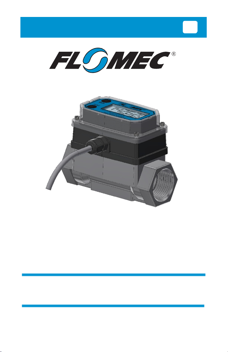
Module shown installed on G2 1” stainless steel flowmeter
EN
09/2021 920907-01 Rev. C
4-20mA MODULE
FOR USE WITH MOST* FLOM EC TURBINE METERS
WITH Q9 DISPLAY
*FLOMEC QSE meters have their own 4-20mA module
1
Page 2

Please save these instructions for future reference. Read carefully before attempting
to assemble, install, operate or maintain the product described.
Protect yourself and others by observing all safety information. Failure to comply with
instructions could result in personal injury and/or property damage.
Please refer to back cover for information regarding this product’s warranty and other
important information.
DO NOT RETURN THIS PRODUCT TO THE STORE!
Please contact Great Plains Industries, Inc.® before returning any product. If you are
missing parts, or experience problems with your installation, contact our Customer
Support Department. We will be happy to assist you.
Call: 888-996-3837 or 316-686-7361
Email: [email protected]
SAVE FOR YOUR RECORDS
Model #: ______________________
Serial #: ______________________
Purch. Date: ___________________
2
Page 3

TABLE OF CONTENTS
Getting Started ------------------------------------------------- 4
Electrical / Mechanical Specifications -------------------- 5
Approval Ratings ----------------------------------------------- 7
Installation ------------------------------------------------------- 8
Installing Module ------------------------------------------ 8
Wiring -------------------------------------------------------- 9
Operation / Calibration -------------------------------------- 11
Troubleshooting ---------------------------------------------- 12
Parts List ------------------------------------------------------- 15
Parts & Service ----------------------------------------------- 15
Warranty -------------------------------------------------------- 16
3
Page 4
BEFORE YOU BEGIN
Usage Requirements
• This 4-20mA module is not FM Approved. Therefore, use of this module
with an approved metering system voids FM Approval.
• This 4-20mA module requires an input power of 8-32 volts DC (24 VDC
is recommended).
• This 4-20mA module is designed for use with most* FLOMEC meters that
are equipped with the Q9 display option. The 4-20mA module can be field
calibrated through the configuration menu options on the Q9 display.
*FLOMEC QSE meters have their own 4-20mA module.
UNPACKING/INSPECTION
Inspect
• After unpacking the unit, inspect carefully for any damage that may have
occurred during transit. Check for loose, missing or damaged parts.
Shipping damage claims must be filed with carrier.
• See General Safety Instructions, and all Cautions, Warnings, and Dangers
as shown.
4
Page 5
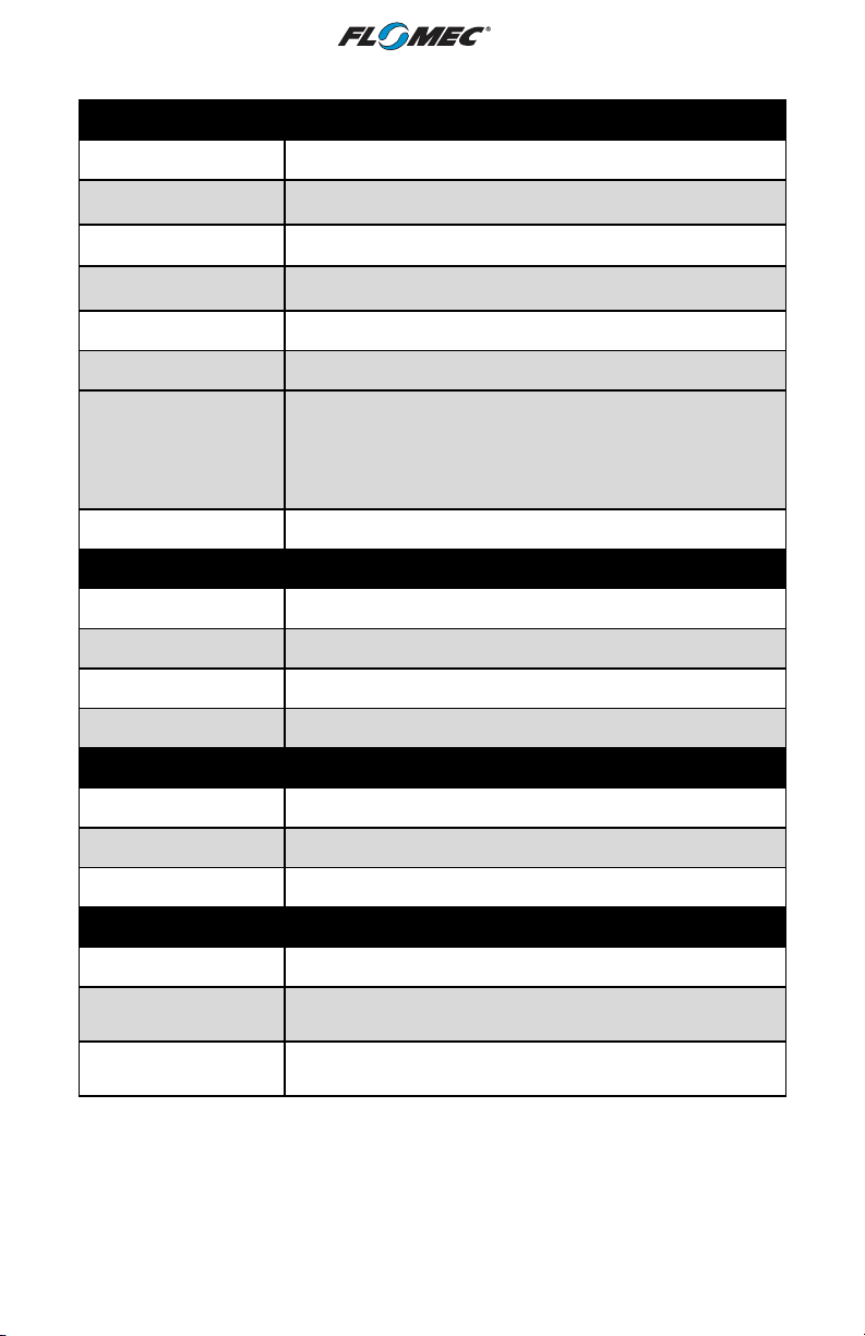
Hubble PG7. Grip range
(Cable Outside Diameter)
Belden 9363 (22 AWG
-
3 conductor
When
i
nstalled on G2
S
tainless Steel Flowmeters,
see
SPECIFICATIONS
Mechanical
Housing material: Nylon 6/6
Strain relief:
0.11 - 0.26 in. (2.8 – 6.6 mm)
Housing port thread: Female 1/2-20 UNF-2B (Compatible with PG7)
Cable
with drain wire and shield)
Cable length 10 ft. (3m), provided
Operating Temperature
Higher Process Fluid
Temperatures
Obtainable with G2
Stainless Steel Meters
Ambient and Fluid Temperature Limits graph on next page
for higher process fluid temperature Limits.
If wider process fluid temperature ranges are desired,
reference information on FLOMEC® Remote Kits.
0° to +140°F (-18° to +60°C)
Storage temperature: -40° to +180°F (-40° to +82°C)
Power:
Type: Loop powered
Voltage minimum: 8 VDC
Voltage maximum: 32 VDC
Isolated: No
Primary Output (4-20mA):
Type: Loop
Minimum: 4 mA
Maximum: 25 mA
Scaled Pulse Output:
Type: Open Collector (NPN), Current Sinking
External Pull Up
Voltage 1
Internal Pull Up Voltage
2
1
NOTE: Customer supplied external voltage with separate power supply and a minimum
external pull up resistance of 820 ohms.
2
NOTE: 5VDC supplied internal on the 4-20mA board, no external supply or pull up
resistor required. Internal pull up is fixed at 100K ohm
8.0 to 26 VDC
5.0 VDC
5
Page 6
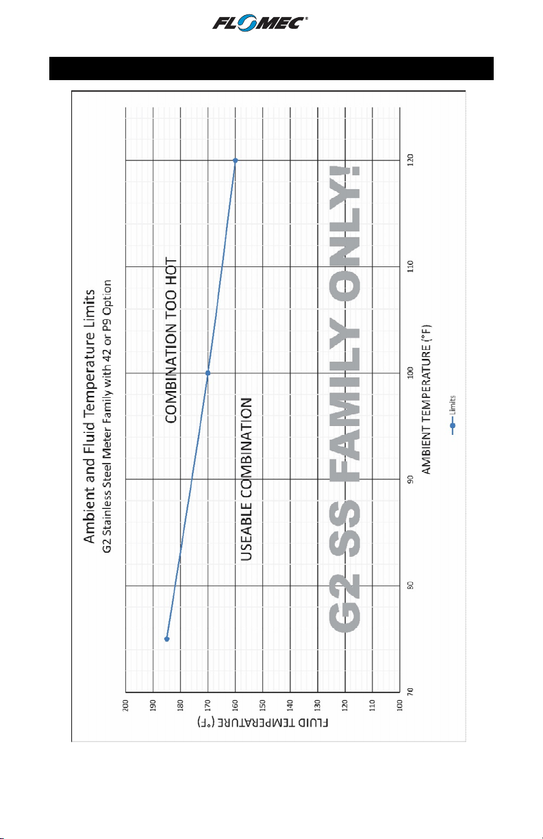
AMBIENT AND FLUID TEMPERATURE
LIMITS
SPECIFICATIONS (continued)
NOTE: The upper limit of the “Useable Combination” area can be increased by 10°F (6°C)
when lithium batteries are installed in the Q9 Display.
6
Page 7
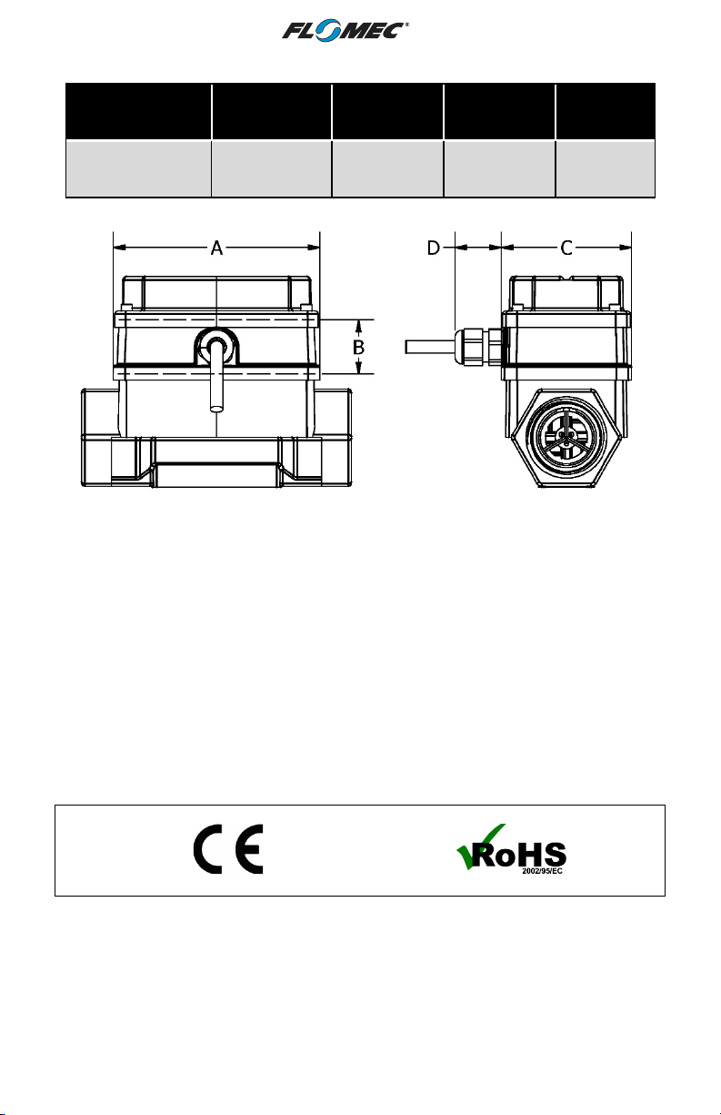
SPECIFICATIONS (Continued)
Dimensions
4-20mA Module
Module shown installed on G2 1” stainless steel flowmeter
Figure 1
Note: This 4-20mA module is designed for use with most* FLOMEC meters that are equipped
with the Q9 display option. The 4-20mA module can be field calibrated through the
configuration menu options on the Q9 display.
*FLOMEC QSE meters have their own 4-20mA module.
Length
(A)
3.45 in.
(88 mm)
Height
(B)
0.90 in.
(23 mm)
Width
(C)
2.18 in.
(55 mm)
Strain
Relief
(D)
0.86 in.
(22 mm)
APPROVAL RATINGS
7
Page 8
INSTALLATION
Installing Module
NOTE: Factory installed 4-20mA modules will have the zero set to the meter’s minimum
specified flow rate and the span will be set to the meter’s maximum specified flow rate.
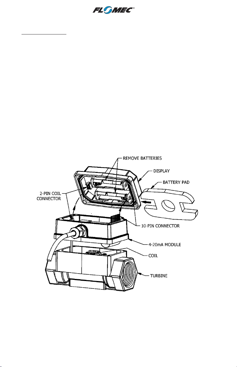
1. Remove the display electronics from the front of the turbine.
NOTE: If you are installing more than one module at a time, take care to keep the proper
electronics paired with the original turbine.
NOTE: If your display currently has batteries installed, you will need to remove them
to enable the 4-20mA and scaled pulse output to function.
2. Disconnect 2-pin coil connector from display. Make sure coil remains firmly attached to
meter body (DO NOT pull on wires or attempt to remove from meter body).
3. Connect the 4-20mA Module to the 10-pin connector located on the backside of the
computer electronics (see Figure 2).
4. Reconnect the coil connector to the 2-pin terminal block on the other end of the computer
backside. Once the cables are installed on the display, the housing of the display can be
placed on top of the 4-20mA module (see Figure 2).
5. Install the computer electronics to the front side of the turbine. Tighten the four screws
snugly.
Module shown installed on G2 1” stainless steel flowmeter
Figure 2
8
Page 9
INSTALLATION (Continued)
Wiring
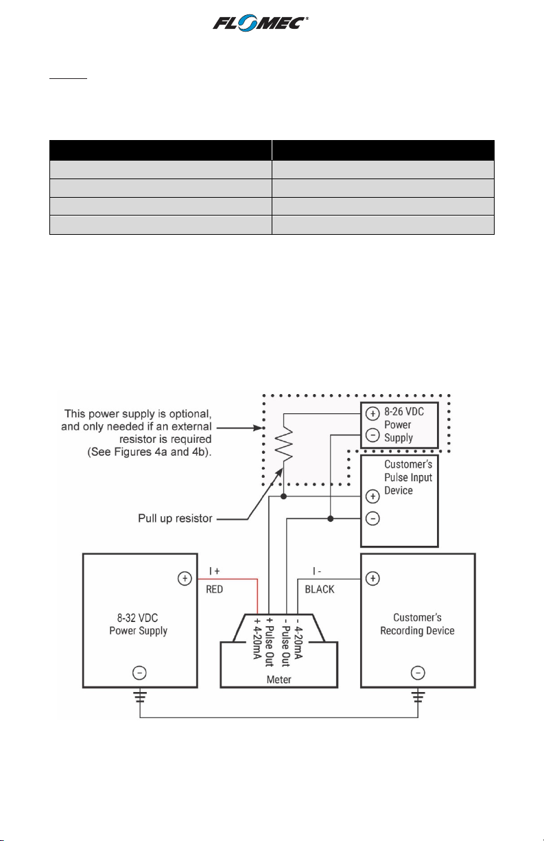
The 4-20mA module comes pre-wired for external connections to external power and
provides an open collector output, which can be set to either raw or scaled pulse output. The
wires are color coded to connect as shown in Figures 3 & 4.
Wire Color Feature
Red 4-20mA (+)
Black 4-20mA (-)
White Pulse Out (+)
Uninsulated Pulse Out (-)
NOTE: The 4-20mA board provides a pulse output on the White wire with the cable shield
as the ground (return). This is set to raw pulse output as the default setting on the Q9 display.
If your application requires a scaling of the pulse output, refer to the installation instructions
to enable the scaled pulse feature and refer to the Q9 owner’s manual for instructions on the
configuration of the scaled pulse feature.
NOTE: If using the scaled pulse output feature, use the scaled K-factor in the user interface
device.
NOTE: The ground of the pulse output must be galvanically isolated from the 4-20mA loop
ground (return).
Figure 3
9
Page 10
INSTALLATION (Continued)
WIRING (Continued)
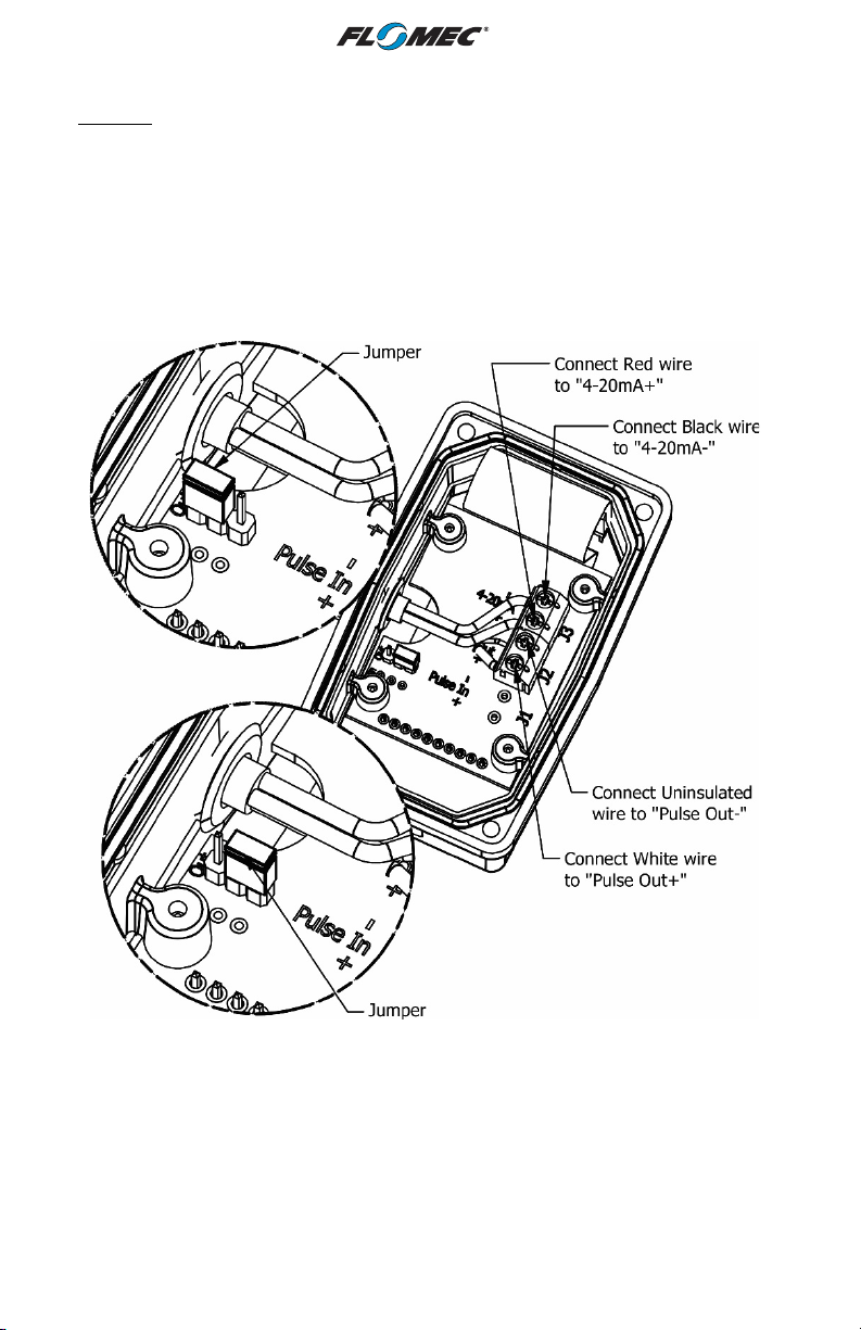
NOTE: The internal and external options for the pull up resistance and voltage is selectable
by the header on the 4-20mA board (see Figures 4a & 4b).
When the Jumper is on the top two pins, the “external resistor required” option is selected
(Figure 4a). This external resistor can be installed as shown on Figure 3, but could also be
built into the existing customer equipment.
When the Jumper is located on the bottom two pins, the “internal resistor” option is selected
(Figure 4b).
Figure 4a
Figure 4b
10
Page 11
OPERATION / CALIBRATION
Adjusting ZERO and SPAN
To set or adjust ZERO and SPAN settings, refer to the Q9 Owner’s Manual (Non-Agency)
Configuration Mode (Daughter Board Options) and Calibration Mode Section for further
instructions.
NOTE: The Q9 Display controls the 4-20 mA settings. It is recommended to verify and set
(if necessary) the most optimal Calibration Method of the Q9 Display (see Q9 Owner’s
Manual referenced above) before adjusting 4-20mA settings.
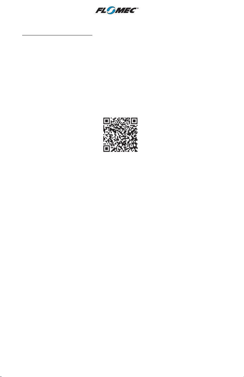
You can download the Q9 Owner’s Manual (Non-Agency) here:
or visit flomecmeters.com to download owner’s manuals and other technical documents.
11
Page 12
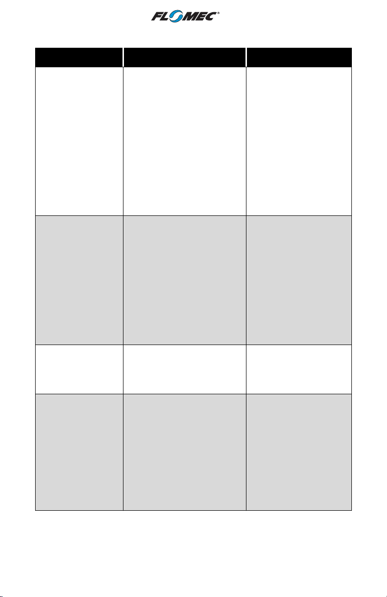
TROUBLESHOOTING
Symptom Possible Cause(s) Corrective Action
A. No output signal.
1. Incorrect or no input power.
2. Not wired correctly.
3. Broken connection.
4. Defective PC board
connector.
5. Defective unit.
6. Batteries installed.
1. Supply correct power
requirements.
2. Check owner’s manual
for correct installation.
3. Check resistance to
determine location of
break.
4. Contact distributor or
factory for replacement
5. Contact distributor or
factory for replacement.
6. Remove batteries and
cycle loop power.
1. ZERO and SPAN not set
correctly on the Q9 display.
B. Signal not between
4-20mA when fluid
is flowing.
C. Scaled Pulse
output not working
or not shown in Q9
configuration
options menu.
D. Pulse output values
are not giving
accurate total
volumes.
2. 4-20 mA Module output signal
"ZERO" and "SPAN" does
NOT match customer's
recording device "ZERO" and
"SPAN" settings.
3. Q9 display calibration is NOT
optimized for best results.
1. Batteries being installed will
disable the Scaled Pulse
output feature.
1. Customer's "pulse Input
device" (pulses per unit of
volume) does not match
module pulse output (pulses
per unit of volume).
2. Q9 display calibration is NOT
optimized for best results.
1. Check Q9 owner’s
manual for instructions
on how to set ZERO and
SPAN for meter.
2. Reconfigure 4-20mA
Module output signal
"ZERO" and "SPAN" to
match Customer's
recording device "ZERO"
and "SPAN" (or vice
versa).
3. Verify Q9 display value is
giving correct flowrate.
1. Remove batteries, cycle
loop power and
reconfigure the Scaled
Pulse output feature on
Q9 display.
1. Reconfigure module
pulse output (or
customer's "pulse input
device") to match in
pulses per unit of volume
(module output pulses
per unit of volume = input
pulses per unit of
volume).
2. Verify Q9 display value is
giving correct volume
totals.
12
Page 13
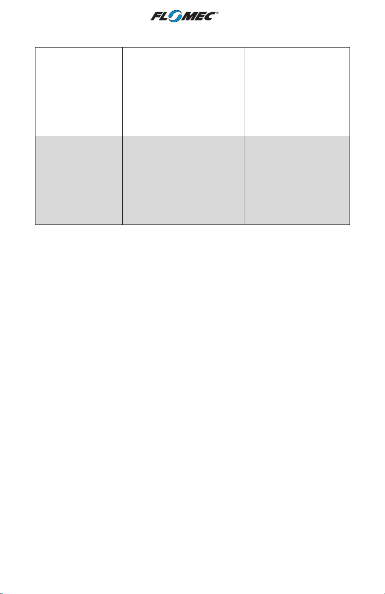
TROUBLE SHOOTING (Continued)
1. Q9 display showing velocity or
volume totals instead of
flowrate.
E. Q9 display value
not giving correct
Flowrate.
F. Q9 display value
not giving correct
volume totals.
2. Q9 display calibration is not
optimized for best results.
1. Q9 display showing velocity,
flowrate, or accumulative total
instead of batch total.
2. Q9 display calibration is not
optimized for best results.
1. Press "top button" of Q9
display until flowrate is
displayed (see Operation
Section in Q9 owner's
manual).
2. If "1" above is not the
Issue, See
Operation/Calibration
Section of this manual
1. Press "bottom button" of
Q9 display until correct
volume is displayed (see
Operation Section in Q9
owner's manual).
2. If "1" above is not the
Issue, see
Operation/Calibration
Section of this manual.
13
Page 14

NOTES
________________________________________________________________________
________________________________________________________________________
________________________________________________________________________
________________________________________________________________________
________________________________________________________________________
________________________________________________________________________
________________________________________________________________________
________________________________________________________________________
________________________________________________________________________
________________________________________________________________________
________________________________________________________________________
________________________________________________________________________
________________________________________________________________________
________________________________________________________________________
________________________________________________________________________
________________________________________________________________________
________________________________________________________________________
________________________________________________________________________
________________________________________________________________________
________________________________________________________________________
________________________________________________________________________
________________________________________________________________________
________________________________________________________________________
________________________________________________________________________
14
Page 15
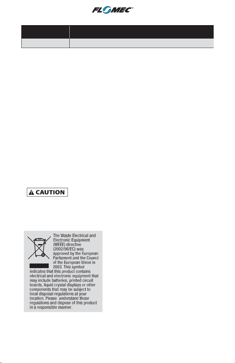
PARTS LIST
Part Number Description
901002-52 Seal
PARTS & SERVICE
For warranty consideration, parts, or other service information, please contact
your local distributor. If you need further assistance, contact the GPI Product
Support Department in Wichita, Kansas, during normal business hours.
A toll free number is provided for your convenience.
1-888-996-3837
To obtain prompt, efficient service, always be prepared with the following
information:
• The model number of your meter.
• The serial number or manufacturing date code of your meter.
• Part descriptions and numbers.
For warranty work, always be prepared with your original sales slip or other
evidence of purchase date.
IMPORTANT: Please contact GPI before returning any parts. It may be
possible to diagnose the trouble and identify needed parts in a telephone call.
Do not return this product without prior approval from the GPI Product
Support Department. Due to strict government regulations, GPI cannot
accept parts unless they have been drained and cleaned.
WEEE DIRECTIVE
15
Page 16

FLOMEC® TWO-YEAR LIMITED WARRANTY
Great Plains Industries, Inc. 5252 E. 36th Street North, Wichita, KS USA 67220-3205, hereby
provides a limited warranty against defects in material and workmanship on all products
manufactured by Great Plains Industries, Inc. This product includes a 2-year warranty.
Manufacturer’s sole obligation under the foregoing warranties will be limited to either, at
Manufacturer’s option, replacing or repairing defective Goods (subject to limitations
hereinafter provided) or refunding the purchase price for such Goods theretofore paid by the
Buyer, and Buyer’s exclusive remedy for breach of any such warranties will be enforcement
of such obligations of Manufacturer. The warranty shall extend to the purchaser of this
product and to any person to whom such product is transferred during the warranty period.
The warranty period shall begin on the date of manufacture or on the date of purchase with
an original sales receipt. This warranty shall not apply if:
A. the product has been altered or modified outside the warrantor’s duly appointed
representative;
B. the product has been subjected to neglect, misuse, abuse or damage or has been
installed or operated other than in accordance with the manufacturer’s operating
instructions.
To make a claim against this warranty, or for technical assistance or repair, contact your
FLOMEC distributor or contact FLOMEC at one of the locations below.
In North or South America contact
Great Plains Industries, Inc.
5252 East 36th St. North
Wichita, KS 67220-3205
USA
888-996-3837
www.flomecmeters.com
(North America)
The company will step you through a product troubleshooting process to determine
appropriate corrective actions.
Outside North or South America contact
GPI Australia
(Trimec Industries Pty. Ltd.)
12/7-11 Parraweena Road
Caringbah NSW 2229
Australia
+61 02 9540 4433
www.flomec.com.au
GREAT PLAINS INDUSTRIES, INC., EXCLUDES LIABILITY UNDER THIS WARRANTY
FOR DIRECT, INDIRECT, INCIDENTAL AND CONSEQUENTIAL DAMAGES INCURRED IN
THE USE OR LOSS OF USE OF THE PRODUCT WARRANTED HEREUNDER.
The company herewith expressly disclaims any warranty of merchantability or fitness for any
particular purpose other than for which it was designed.
This warranty gives you specific rights and you may also have other rights which vary from
U.S. state to U.S. state.
NOTE: In compliance with MAGNUSON MOSS CONSUMER WARRANTY ACT – Part 702
(governs the resale availability of the warranty terms).
© 2021 Great Plains Industries, Inc., All Rights Reserved.
Great Plains Industries, Inc. / 888-996-3837 / flomecmeters.com
09/2021 920907-01 Rev. C
16
 Loading...