

Page 1

User’s Guide
Shop online at
omega.com
e-mail: [email protected]
For latest product manuals:
omegamanual.info
Page 2

OMEGAnet®Online Service Internet e-mail
omega.com [email protected]
Servicing North America:
U.S.A.: Omega Engineering, Inc., One Omega Drive, P.O. Box 4047
ISO 9001 Certified
Stamford, CT 06907-0047
Toll-Free: 1-800-826-6342 Tel: (203) 359-1660
FAX: (203) 359-7700 e-mail: [email protected]
Canada: 976 Bergar
Laval (Quebec), Canada H7L 5A1
Toll-Free: 1-800-826-6342 TEL: (514) 856-6928
FAX: (514) 856-6886 e-mail: [email protected]
For immediate technical or application assistance:
U.S.A. and Canada: Sales Service: 1-800-826-6342/1-800-TC-OMEGA
Customer Service: 1-800-622-2378/1-800-622-BEST
Engineering Service: 1-800-872-9436/1-800-USA-WHEN
®
®
®
Mexico: En Español: 001 (203) 359-7803 FAX: (001) 203-359-7807
Servicing Europe:
Benelux: Managed by the United Kingdom Office
Czech Republic: Frystatska 184
France: Managed by the United Kingdom Office
Germany/Austria: Daimlerstrasse 26
United Kingdom: OMEGA Engineering Ltd.
ISO 9001 Certified
It is the policy of OMEGA Engineering, Inc. to comply with all worldwide safety and EMC/EMI
regulations that apply. OMEGA is constantly pursuing certification of its products to the European New
Approach Directives. OMEGA will add the CE mark to every appropriate device upon certification.
The information contained in this document is believed to be correct, but OMEGA accepts no liability for any
errors it contains, and reserves the right to alter specifications without notice.
WARNING: These products are not designed for use in, and should not be used for, human applications.
733 01 Karviná, Czech Republic
Toll-Free: 0800-1-66342 TEL: +420-59-6311899
FAX: +420-59-6311114 e-mail: [email protected]
Toll-Free: 0800 466 342 TEL: +33 (0) 161 37 29 00
FAX: +33 (0) 130 57 54 27 e-mail: [email protected]
D-75392 Deckenpfronn, Germany
Toll-Free: 0 800 6397678 TEL: +49 (0) 7059 9398-0
FAX: +49 (0) 7056 9398-29 e-mail: [email protected]
One Omega Drive, River Bend Technology Centre, Northbank
Irlam, Manchester M44 5BD England
Toll-Free: 0800-488-488 TEL: +44 (0)161 777-6611
FAX: +44 (0)161 777-6622 e-mail: [email protected]
Page 3
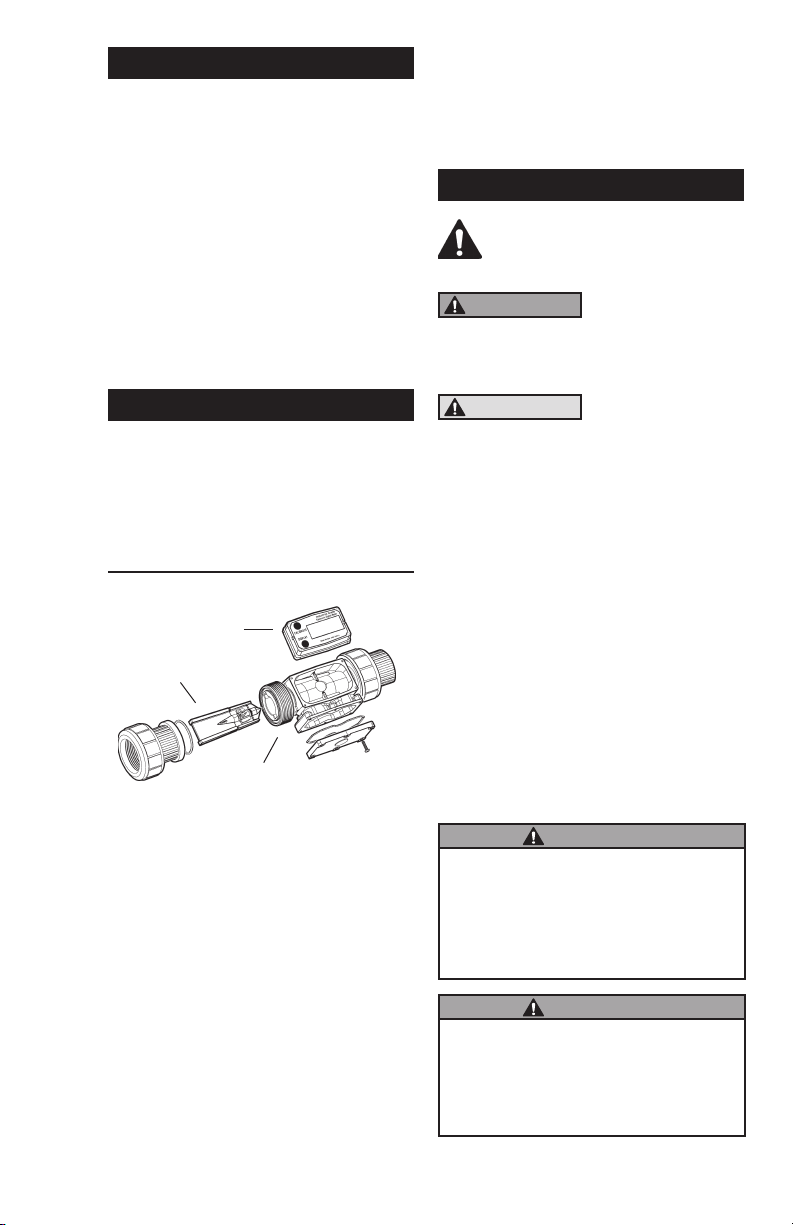
TABLE OF CONTENTS
General Information ........................1
Installation ......................................3
Operation ........................................4
Calibration ......................................5
Maintenance ...................................6
Troubleshooting ..............................8
Specications .................................9
Model Numbers ............................12
Parts & Accessories......................12
Warranty/Disclaimer .....................13
Return Requests/Inquiries ............13
Series Turbine Meter System prior
to installation and use. If you need
assistance, contact the Omega Flow
Application Department.
SAFETY INSTRUCTIONS
This symbol is used throughout
the manual to call your attention
to safety messages.
WARNING
WARNINGS
you to the poten-
alert
tial for personal
injury.
GENERAL INFORMATION
This manual will assist you in installing
and maintaining your FTB890 Series
turbine meter and associated display
electronics. The turbine meters can be
purchased with or without the display
electronics. (See Figure 1)
Figure 1
Computer Electronics
Rotor Assembly
Turbine Housing
When purchased with the display
electronics, optional accessory mod-
ules are available for eld installation.
Information on these accessories
is contained in separate manuals.
Calibration details using the display
electronics are given in this manual.
When purchased without the display
(Sufx - ND) an optional eld installable
Pulse Output Module (FLSC790-PND) is available and described in a
separate manual.
For best results, take the time to fully
acquaint yourself with all information
about all components of your FTB890
CAUTION
CAUTIONS call
your attention to
practices or procedures which
may damage your
equipment.
NOTES give information that can
improve efciency of operations.
It is your responsibility to make sure
that all operators have access to
adequate instructions about safe operating and maintenance procedures.
Read Me!
For your safety, review the major
warnings and cautions below before
operating your equipment.
WARNING
The apparatus enclosure may contain
aluminum and is considered to constitute a potential risk of ignition by
impact or friction. Care must be taken
into account during installation and use
to prevent impact or friction.
WARNING
Part of the enclosure is constructed
from plastic. To prevent the risk of
electrostatic sparking the plastic
surface should only be cleaned with a
damp cloth.
1
Page 4

1. This equipment is approved to
handle only uids that are compatible with all materials of construction.
2. When measuring ammable liquids,
observe precautions against re or
explosion.
3. When handling hazardous liquids,
always follow the liquid manufacturer’s safety precautions.
4. When working in hazardous
environments, always exercise
appropriate safety precautions.
5. Always dispose of used cleaning
solvents in a safe manner according to the solvent manufacturer’s
instructions.
6. During turbine removal, liquid may
spill. Follow the liquid manufacturer’s safety precautions for clean
up of minor spills.
7. Do not blow compressed air
through the turbine.
8. Do not allow liquids to dry inside
the turbine.
9. Handle the rotor carefully. Even
small scratches or nicks can affect
accuracy.
10. When tightening the turbine, do not
use a wrench or pliers to tighten
the turbine. Hand tighten only.
11. For best results, always verify accuracy before use.
Product Description
Omega Industrial Meter Turbines are
identied by the internal diameter of
the inlet and outlet.
FTB891 - 1/2 inch
FTB893 - 1 inch
Each turbine is designed to work with
on-
board computer electronics and/
or with one of several accessory modules that can interface to a wide variety of reporting and collecting devices.
The CMOS microprocessor-based
electronics have extremely low power
requirements and data retention
capabilities in both RAM and ROM.
Information is clearly displayed on a
large 6-digit LCD readout with two-
point oating decimal for totals from
.01 to 999,999. All operations are
easily accessed with the two buttons
on the front panel.
Liquid ows through the turbine housing causing an internal rotor to spin.
As the rotor spins, an electrical signal
is generated in the pickup coil. The
electrical signal provides the output
necessary to operate the on-board
computer electronics for local indication
directly on the turbine or one of several
accessory modules that transmit the
signal to external equipment.
Upon receipt, examine your meter
for visible damage. The turbine is a
precision measuring instrument and
should be handled as such. Remove
the protective plugs and caps for a
thorough inspection. If any items are
damaged or missing, contact your
distributor.
Make sure the turbine model meets
your specic needs. Refer to the
Specications Section and conrm
the following:
1. The owrate is within the limits of
your model.
2. The liquid is compatible with the
turbine’s wetted components.
3. The system’s pressure does not
exceed the turbine’s maximum
pressure rating.
Each Omega Turbine has a unique
identication number that includes
the Serial Number, Model Number,
Manufacturing Date, and K-Factor.
This identication number is etched
into the surface of the turbine. Record
this identication number in the back
of the Owner’s Manual and keep for
future reference.
2
Page 5

SN = Serial Number, a 7-8 dig-
it number that identifies this
particular turbine.
MOD = Model number
KF = K-Factor given in pulses per
gallon (PPG).
MFD = Manufacturing Date indicating
the week and year of manufacture.
INSTALLATION
All Omega turbines are designed to
measure ow in only one direction.
The direction is indicated by the arrow
cast-molded in the turbine outlet. If the
opposite direction is desired, and you
are using on-board computer electronics, rotate the computer electronics 180
degrees prior to installation.
Flow altering devices such as elbows,
valves, and reducers can affect accuracy. The following recommended
guidelines are given to enhance ac-
curacy and maximize performance.
Distances given here are minimum
requirements; double them for desired
straight pipe lengths.
Upstream from the turbine, allow a
minimum straight pipe length at least
10 times the internal diameter of the
turbine. For example, with the FTB893
turbine, there should be 10 inches (25.4
cm) of straight pipe immediately upstream. The desired upstream straight
pipe length is 20 inches (50.8 cm).
Downstream from the turbine, allow a
minimum straight pipe length at least
5 times the internal diameter of your
turbine. For example, with the FTB893
turbine, there should be 5 inches
(12.7 cm) of straight pipe immediately
downstream. The desired downstream
distance is 10 inches (25.4 cm).
A typical back pressure of 5 to 50 PSI
(0.34 to 3.4 bar) will prevent cavitation.
Create back pressure by installing a
control valve on the downstream side
of the meter at the proper distance
detailed above.
Foreign material in the liquid being
measured can clog the turbine’s rotor
and adversely affect accuracy. If this
problem is anticipated or experienced,
install screens to lter impurities from
incoming liquids.
FTB891
Maximum Particulate Size
Inches: 0.005
Microns: 125
Mesh: 55
Standard Sieve: 125 µm
Alternative Sieve: No. 120
FTB893
Maximum Particulate Size
Inches: 0.018
Microns: 500
Mesh: 28
Standard Sieve: 500 µm
Alternative Sieve: No. 35
The PVDF Series FTB890 turbines
are Factory Mutual Approved and
carry a Class 1, Division 1 Approval
for hazardous environments. Omega
Meters are tested and calibrated at the
factory using state-of-the-art calibration test equipment.
To ensure accurate measurement,
remove all air from the system before
use. To purge the system of air:
1. Ensure some back pressure on
the turbine.
2. Open the discharge valve or nozzle
and allow uid to completely ll the
system. Make sure the stream is
full and steady.
3. Close the discharge valve or
nozzle.
4. Start normal operations.
Each turbine contains a removable
back coverplate. Leave the coverplate
installed unless accessory modules
specify removal.
3
Page 6

Connections
1. To protect against leakage, seal
all threads with an appropriate
sealing compound. Make sure
the sealing compound does not
intrude into the ow path.
2. Make sure the ow direction arrow
on housing back is pointed in the
direction of the ow.
3. Install union ring over pipe end
prior to installing pipe tting.
4. Install pipe ttings on pipe ends,
and tighten.
5. Tighten union ring to the turbine.
Make sure O-ring is positioned in
housing ends. Do not use a wrench
or pliers. Hand tighten only.
NOTE: If connecting to new male
threads, burrs and curls can
adversely affect accuracy. Correct the problem prior to turbine
installation.
It is strongly recommended that ac-
curacy be veried prior to use. To do
this, remove all air from the system,
measure an exact known volume into
an accurate container, and verify the
volume against the readout or recording equipment. If necessary, use a
correction factor to gure nal volume.
For best results, accuracy should be
veried periodically as part of a routine
maintenance schedule. The procedure
is found in the Maintenance Section.
The display electronics is normally
installed on the turbine housing at the
factory unless ordered without it.
If for any reason the display electronics
need to be mounted on your turbine,
simply mount the display on the turbine
with the four screws at the corners
of the faceplate. Make sure the seal
is fully seated before tightening the
screws.
If you ordered the FTB890 Series
turbine with an accessory module,
please review and thoroughly under-
stand all installation instructions before
proceeding.
Avoid electronically “noisy” environments. Install at least 6 inches (15.2
cm) away from motors, relays, or
transformers.
OPERATION
Computer Display
All operations are reected in the
LCD readout. The large center digits
indicate amounts, where smaller words
or “icons” located above and below
indicate spcic information regarding
totals, ow, calibration and units of
measure.
Activate the Meter
Computer is on continuously and always ready to perform. The computer
is powered by eld replaceable batteries. When display becomes dim, faded
or the low battery message appears
(see below), the batteries need to be
replaced. Reference the Maintenance
Section for details.
Batch and Cumulative Totals
The computer maintains two totals.
The Cumulative Total provides continuous measurement and cannot be
manually reset. The Batch Total can be
reset to measure ow during a single
use. The Cumulative Total is labeled
TOTAL 1, Batch Total is labeled TOTAL
2 BATCH.
When the Cumulative Total reaches a
display reading of 999,999 the computer will highlight an X10 icon. This
indicates to the operator that a zero
must be added to the 6 digits shown.
When the next rollover occurs, the
computer will highlight an X100 icon.
This indicates to the operator that
two zeroes must be added to the 6
digits shown.
4
Page 7

Press the DISPLAY button briey to
switch between the TOTAL 1, TOTAL
2 BATCH and FLOWRATE. Press
DISPLAY briey to display the TOTAL 2
BATCH. Hold the DISPLAY button for 3
seconds to reset the Batch Total to zero.
When uid is owing through the meter,
a small propeller icon is highlighted.
The “eld” calibration may be set by the
user, and can be changed or modied
at any time using the calibration procedure described below in the Calibration
Section. Totals or owrate derived from
the eld calibration are invoked when
the FAC icon is no longer visible on
the top line of the display.
Flowrate Feature
To use this feature, press and release
DISPLAY until FLOWRATE icon appears. The factory set time base will be
highlighted to the right of FLOWRATE
(M = minutes, H = hours, D = days).
When FLOWRATE is invoked, the
display will be indicating rate of ow.
Factory and Field Calibration
All calibration information is visible to
the user as icons on the top line of
the display, above the numeric digits.
All units are congured with a “factory”
calibration. Both gallons and litres
are available (“GL” or “LT” will be displayed). While holding the CALIBRATE
button, briey press DISPLAY to toggle
between gallons and litres. This factory calibration (indicated with FAC)
is permanently programmed into the
computer and is not user adjustable.
NOTE: Your computer may have other
units of measure programmed into
it. If so, holding the CALIBRATE
button and momentarily pressing
the DISPLAY button will toggle
through all factory set units. Other
possible units are: IGL (imperial
gallon), QT (quart), CF (cubic feet),
CM (cubic meter), BL (42 gal.
barrel), CC (cubic centimeter) or
OZ (ounce).
Switching between different units will
not corrupt the Total’s contents. For
example, in GL mode, the computer
totalizes 10.00 gallons, if the user
switches to LT mode, the display will
read 37.85 litres (the same volume,
different unit).
CALIBRATION
Verify Accuracy Before
Beginning Field Calibration
For the most accurate results, dispense at a owrate which best simulates your actual operating conditions.
Avoid “dribbling” more uid or repeatedly starting and stopping the ow. This
can result in less accurate calibrations.
Make sure you meet the meter’s mini-
mum owrate requirements:
1/2 inch meter 0.6 GPM (2.2 LPM)
1 inch meter 2.5 GPM (9.5 LPM)
The use of a uniformly dependable,
accurate calibration container is
recommended for the most accurate
results. For best results, the meter
should be installed and purged of air
before eld calibration.
Field Calibration with
Computer Display
Field Calibration and Factory Cali-
bration are dened in the Operation
Section. Factory calibration settings
are programmed into each computer
during manufacturing, using Stoddard
test solvent at 70° F (21° C). Settings
are correct for light liquids such as
water, gasoline or diesel. Readings
using the Factory Calibration (FAC)
may not be accurate in some situations,
for example, “heavy” liquids such as
motor oil under extreme temperature
conditions, non-standard plumbing
congurations or with uids other than
those mentioned above.
5
Page 8
For improved accuracy under such
conditions, the computer allows for
“eld” calibration, that is, user entry
of custom calibration parameters. A
“single point” calibration may yield
acceptable accuracy when used in a
non-standard application.
Field Calibration Procedures
(Dispense/Display Method)
1. To eld calibrate, press and hold
the CALIBRATE and DISPLAY
buttons for about 3 seconds until
you see FLdCAL. Release both
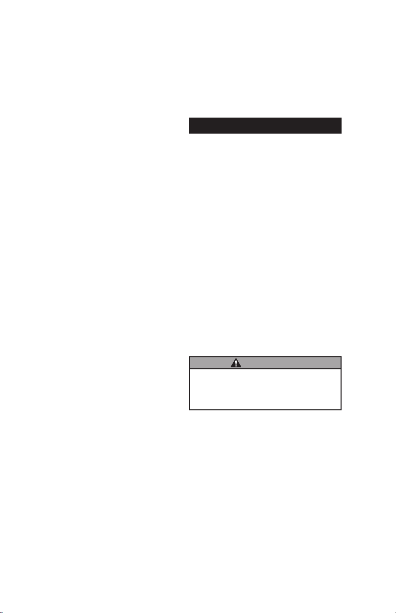
buttons and you will see dd000.0.
You are now in the eld calibration
mode.
2. Dispense a known amount of uid
at a owrate representative of the
application. Any amount between
.1 and 999.9 units can be used.
Display will count up while uid is
owing through the meter.
3. The DISPLAY button can then be
pushed to select the digit location
and the CALIBRATE button can be
pushed to scroll the desired value
at the blinking position. Edit the
amount shown with the value that
was dispensed above. Values from
000.1 to 999.9 can be entered.
4. When satised with the value,
press both CALIBRATE and
DISPLAY buttons simultaneously.
CALEnd will be displayed and unit
will go back to normal operation,
less the FAC (factory calibration)
icon.
5. The meter will now be operating
with a custom calibration number
unique to the dispense procedure.
No unit of measure (gallon, litre,
etc.) icon will be highlighted.
NOTE: To return to factory calibra-
tion (FAC), press and hold both
CALIBRATION and DISPLAY
buttons for about 3 seconds,
until FAcCAL is displayed. Then
release buttons. Unit should re-
turn to normal operation and FAC
icon is visible.
NOTE: If the eld calibration mode is
entered and NO uid is dispensed,
then upon leaving, the computer
will use data from the last success-
ful eld calibration.
MAINTENANCE
Verify Accuracy
Before use, check the turbine’s accuracy and verify calibration.
1. Make sure there is no air in the
system.
2. Measure an exact known volume
into an accurate container.
3. Verify the volume against the
readout or recording equipment.
NOTE: If necessary, use a correction
factor to gure nal volume.
For best results, accuracy should be
veried periodically as part of a routine
maintenance schedule.
Remove the Turbine
WARNING
During turbine removal, liquid may spill.
Follow the liquid manufacturer’s safety
precautions for clean up of minor spills.
1. Ensure all liquid is drained from the
turbine. Wear protective clothing as
necessary.
2. Loosen both union rings at the
ends of the turbine.
3. If the turbine is not immediately
installed again, cap lines as necessary.
Replace Internal Parts
1. Remove the turbine from the system. See Figure 5.
6
Page 9
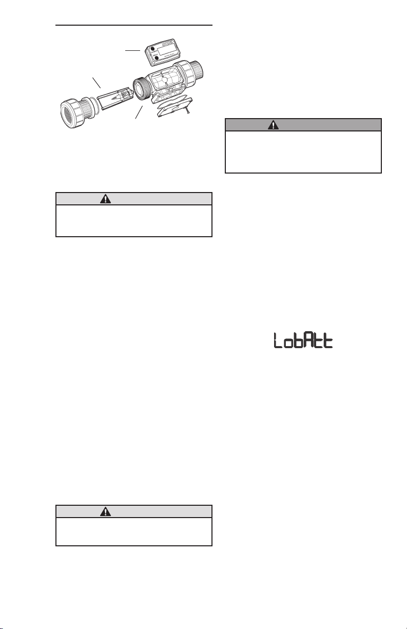
Computer Electronics
Rotor Assembly
Figure 5
parts. Remove internal parts as
detailed above. Note orientation
carefully for correct assembly.
Internal parts can be soaked for
10 to 15 minutes in compatible
cleaning solutions. Use a soft
brush or small probe to carefully
remove residue from the rotor.
Turbine Housing
2. Use your ngers to gently remove the rotor assembly from
the groove. Do not use force to
remove the rotor assembly.
CAUTION
Handle the rotor carefully. Even small
scratches or nicks can affect accuracy.
3. Use the procedure below to clean
the turbine.
4. Install the rotor assembly into the
turbine housing. Make sure the
pointed end of the rotor assembly is
inserted rst. (see Figure 5) Guide
the assembly into place using a
smooth motion, little or no force is
required.
5. Reinstall the turbine, purge the
system of air, and verify accuracy
before use.
Clean the Turbine
During use, the turbine should be kept
full of liquid to ensure that drying does
not occur inside the turbine. If drying
or caking should occur, the rotor will
stick or drag, affecting accuracy. To
determine if the rotor is stuck or dragging, remove rotor from housing and
physically turn rotor.
CAUTION
Never blow compressed air through the
meter. It could damage the rotor.
1. Remove the turbine from the system following the directions above.
2. Carefully clean residue off all
WARNING
Follow the liquid manufacturer’s
instructions for the disposal of
contaminated cleaning solvents.
3. When the rotor turns freely, assemble
and install it again following the instructions above.
Display Electronics
The display electronics are powered
by lithium batteries. If the meter’s
readout should become dim, blank
or the low battery message appears
(see below), the batteries should be
replaced. Replacement batteries can
be ordered from the factory. See details
in the Parts Section.
When batteries are disconnected or
fail, the Batch and Cumulative Totals
values will remain. Factory and Field
Calibration Curves are retained in the
meter’s computer when power is lost.
It is strongly recommended that battery
check and terminal cleaning be a part
of a routine maintenance schedule.
Battery terminals should be cleaned
annually. Batteries can be replaced
without removing the meter from the
piping system.
Replacing the Batteries
1. Remove the corner screws from
the meter face and lift the display
electronics from the turbine.
2. Remove the batteries.
3. Check the battery terminals and
remove any corrosion.
7
Page 10

4. Install the new batteries and make
sure the positive posts are positioned correctly. When the batteries
are installed correctly, the computer
5. Make sure the seal is fully seated
before placing the computer electronics on the turbine. Tighten the
four screws.
powers on automatically and the
readout displays information.
TROUBLESHOOTING
SYMPTOM PROBABLE CAUSE CORRECTIVE ACTION
METER IS NOT
ACCURATE
READOUT FADED
OR BLANK
NORMAL FLOWRATE
BUT METER DOES
NOT COUNT
(Meter comes on
when DISPLAY
button pushed.)
REDUCED FLOWRATE
& METER DOESN'T
COUNT (Meter comes
on when DISPLAY
button pushed.)
1. Field Calibration not
performed properly
2. Factory Calibration not
suitable for liquid being
measured
3. Meter operated below
minimum owrate
4. Meter partially clogged with
dried liquid
5. Turbine bearings partially
clogged with dried liquid
6. Sealant material wrapped
around rotor
7. Installed too close to ttings Install correctly.
8. Installed too close to
motors or electrically
“noisy” environment
9. Improper connections to
recording device
10. Accuracy needs verication Complete normal accuracy verication
1. Batteries weak, dead, or not
connected
2. Display electronics defective Contact the factory.
1. Field Calibration not
performed correctly
2. Rotor stuck or damaged Remove meter.
3. Sealant material wrapped
around rotor
4. Display electronics defective Contact the factory.
1. Meter clogged with dried
liquids
2. Below minimum owrate Increase ow.
Field calibrate again or select Factory
Calibration.
Perform a Field Calibration according
to Calibration Section.
Increase owrate.
Remove meter. Clean carefully.
Make sure rotor spins freely.
Remove meter. Clean carefully.
Make sure rotor spins freely.
Remove meter. Make sure rotor
spins freely.
Install correctly.
Check all electrical connections.
Reference appropriate installation
instructions.
procedures. Repeat periodically.
Remove display electronics. Check
and replace batteries if necessary.
Field Calibrate again or select
Factory Calibration.
Make sure rotor spins freely
Remove meter.
Make sure rotor spins freely
Remove meter. Clean carefully.
Make sure rotor spins freely.
8
Page 11

SPECIFICATIONS
All data on FTB891 and FTB893 determined with 1 centipoise stoddard solvent test
uid at 70° F (21° C).
Models
Size
Linear Flow Range
Gallons/minute (GPM)
Liters/minute (LPM)
Extended Flow Range
Gallons/minute (GPM)
Liters/minute (LPM)
Maximum Flow
Gallons/minute (GPM)
Liters/minute (LPM)
Fluid Velocity in Extended Range
Feet/second
Meters/second
Maximum Pressure Drop in 10:1 Range
PSIG
bar
Frequency Range in Linear Flow Range 45-450 Hz 45-475 Hz
Weight*
Pounds
Kilograms
Ship Weight*
Pounds
Kilograms
FTB891
1/2 in.
1.2-12
4.54-45.4
0.6-12
2.2-45.4
15
56.8
0.5-10.6
0.2-3.2
10.0
0.68
.75 lbs.
.340 kg
1.13 lbs.
.535 kg
FTB893
1 in.
5-50
18.9-190
2.5-50
9.5-190
75
284
0.93-18.6
0.28-5.7
6.0
0.40
1.28 lbs.
.580 kg
1.70 lbs.
.770 kg
* Computer electronics add 0.2 lbs. (0.1 kg) to total weight.
9
Page 12
Performance FTB891 FTB893
Linear Range: 10:1 @ ±2% of reading 10:1 @ ±1.5% of reading
Extended Range: 20:1 @ ±5.0% of reading 20:1 @ ±5.0% of reading
Repeatability: ± 0.3%
Pressure Rating 100 PSIG (6.9 bar)
Wetted Components
Housing: PVDF
Journal Bearings: Ceramic (98% Alumina)
Shaft: Ceramic (98% Alumina)
Rotor and Supports: PVDF
O-Ring: FKM (Standard)
Temperature Range
These temperatures are for the turbine without computer electronics. Final
operational temperature range is determined by computer electronics or accessory modules.
Operating Temperature
-20° to +180° F (-28° to 82° C)
Storage Temperature
-40° to 250° F (-40° to 121° C)
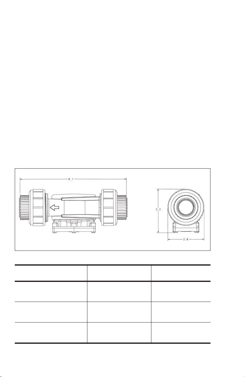
Sample Dimensions for FTB890 Series Model Shown
Length
Width
Height
Dimensions
Models
Size
A = Height:
Inches
Centimeters
B = Width:
Inches
Centimeters
C = Length:
Inches
Centimeters
Computer electronics add 0.7 in. (1.8 cm) to height of turbine.
10
FTB891
1/2 in.
3.2 in.
8.1 cm
2.1 in.
5.3 cm
7.3 in.
18.5 cm
FTB893
1 in.
3.3 in.
8.3 cm
2.8 in.
7.1 cm
8.1 in.
20.5 cm
Page 13
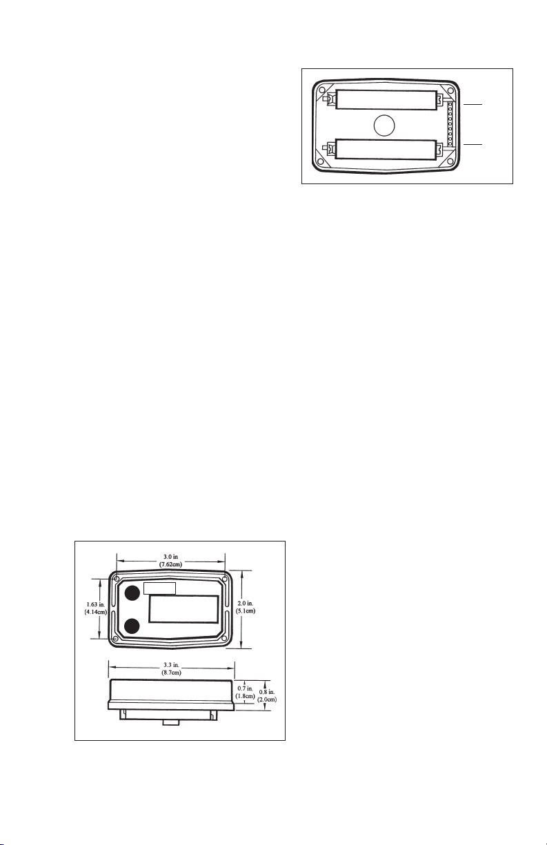
Display Specications
Input Pulse Rate:
Minimum Pulse In: DC
Minimum Coil Input: 10 Hz
Maximum Raw: 1,000 Hz
K-Factor:
Minimum: .01 pulses/unit
Maximum: 999,999 pulses/
unit
Field Calibration:
Minimum Time: 10 seconds
Readout Totals:
Minimum Display: 0.01
Maximum Display: 999,999
Temperatures:
Operational: 0° to +140° F
(-18° to +60° C)
Storage: -40° to +158° F
(-40° to +70° C)
If wider operating temperature ranges
are desired, reference information on
Remote Kits.
Power:
Internal Power Supply: 2 Lithium
Batteries at
3 volts each
Battery Life: 5 years
Optional External Power: 7-30 VDC
Display Electronics Terminal
Connections
J 1
J 10
J-1 Reset
When connected by a jumper
wire to Ground (J1-6), this has
the same effect as initial power
up and zeroes out all totalizers.
J-2 Pulse Signal Output
This supplies a high-level ampli-
ed open collector signal. Output
will withstand a maximum open-
circuit voltage of 60 volts DC
and a maximum closed-circuit
of 100 mA.
J-3 Not Used
J-4 Pulse Signal Input
Requires a sine or square wave
with open-circuit voltage of 3-30
volts P-P, a maximum rise/fall
rate of 0.01 V/µ second and a
maximum frequency of 750 Hz.
J-5 Power Input
When used with Ground (J1-6),
this has reverse polarity protection, but no on-board voltage
regulation. Supplied voltage must
be 5.75 volts DC ±5%.
J-6 Ground
J-7, 8,
9, 10
Programming interfaces.
Not accessable to user-
NOTE: Applicable safety approvals
are void if any external connections are made to computer
electronics.
11
Page 14

MODEL NUMBERS
Model No.
w/Display
FTB891 FTB891-ND
FTB893 FTB893-ND
* Requires signal output module P/N - FLSC790-P-ND ordered separately.
† Extended low ow range and eld calibration for viscosity available on - ND units w/o display.
Model No.*
w/o Display
Range
GPM (LPM)
1.2-12
(4.54-45.4)
5-50
(18.9-190)
Extended
Range
Low Flow†
0.6-12
(2.2-45.4)
2.5-50
(9.5-190)
FNPT
Size
1/2"
1"
PARTS & ACCESSORIES
Order Replacement Kits with the part numbers given here.
Part Number Description
FTB890-ORING O-Ring (Computer)
FTB891-RK FTB891 (1/2 inch) Rotor Assembly Replacement Kit
FTB893-RK FTB893 (1 inch) Rotor Assembly Replacement Kit
FTB891-ORING O-Ring FKM Union Fitting (1/2 inch)
FTB893-ORING O-Ring FKM Union Fitting (1 inch)
Field Installable Options and Accessories
Model Number Description
FLSC790-MA 4-20 mAdc Output Module
FLSC790-P Pulse Output Module
(open collector output)
FLSC790-P-DC External Power Module for FLSC790-P (9-30Vdc)
FTB790-RK Remote Display Kit Module
FTB790-RK-FM FM Approved Remote Display Kit Module
FLSC790-BATT Replacement Batteries
FLSC790-P-ND Pulse Output for Models without Displays
(-ND sufx)
Except as noted, Options and Accessories are for Display Models only and only one Module may be
installed per unit. All models are supplied with 10 ft. cable. Cable may be cut or extended as required.
Customer supplied pull-up resistor required, 820 ohm (min).
(open collector output)
12
Page 15

WARRANTY/ DISCLAIMER
OMEGA ENGINEERING, INC. warrants this u nit to be f ree of defects in materials and
workmanship for a period of 13 months from date of purchase. OMEGA’s WARRANTY adds
an additional one (1) month grace period to the normal one (1) year product warranty to
cover handling and shipping time. This ensures that OMEGA’s customers receive maximum
coverage on each product.
If the unit malfunctions, it must be returned to the factory for evaluation. OMEGA’s Customer
Service Department will issue an Authorized Return (AR) number immediately upon phone or
written request. Upon examination by OMEGA, if the unit is found to be defective, it will be
repaired or replaced at no charge. OMEGA’s WARRANTY does not apply to defects resulting
from any action of the purchaser, including but not limited to mishandling, improper
interfacing, operation outside of design limits, improper repair, or unauthorized modification.
This WARRANTY is VOID if the unit shows evidence of having been tampered with or shows
evidence of having been damaged as a result of excessive corrosion; or current, heat, moistur e
or vibration; improper specification; misapplication; misuse or other operating conditions
outside of OMEGA’s control. Components in which wear is not warranted, include but are not
limited to contact points, fuses, and triacs.
OMEGA is pleased to offer suggestions on the use of its various products. However,
OMEGA neither assumes responsibility for any omissions or errors nor assumes
liability for any damages that result from the use of its products in accordance with
information provided by OMEGA, either verbal or written. OMEGA warrants only
that the parts manufactured by the company will be as specified and free of
defects. OMEGA MAKES NO OTHER WARRANTIES OR REPRESENTATIONS OF ANY
KIND WHATSOEVER, EXPRESSED OR IMPLIED, EXCEPT THAT OF TITLE, AND ALL
IMPLIED WARRANTIES INCLUDING ANY WARRANTY OF MERCHANTABILITY AND
FITNESS FOR A PARTICULAR PURPOSE ARE HEREBY DISCLAIMED. LIMITATION OF
LIABILITY: The remedies of purchaser set forth herein are exclusive, and the total
liability of OMEGA with respect to this order, whether based on contract, warranty,
negligence, indemnification, strict liability or otherwise, shall not exceed the
purchase price of the component upon which liability is based. In no event shall
OMEGA be liable for consequential, incidental or special damages.
CONDITIONS: Equipment sold by OMEGA is not intended to be used, nor shall it be used: (1)
as a “Basic Component” under 10 CFR 21 (NRC), used in or
activity; or (2) in medical applications or used on humans. Should any Product(s) be used in or
with any nuclear installation or activity, medical application, used on humans, or misused in
any way, OMEGA assumes no responsibility as set forth in our basic WARRANTY/ DISCLAIMER
language, and, additionally, purchaser will indemnify OMEGA and hold OMEGA harmless from
any liability or damage whatsoever arising out of the use of the Product(s) in such a manner.
with any nuclear installation or
Direct all warranty and repair requests/inquiries to the OMEGA Customer Service Department.
RETURN REQUESTS/INQUIRIES
BEFORE RETURNING ANY PRODUCT(S) TO O MEGA, PURCHASER MUST OBTAIN AN
AUTHORIZED RETURN (AR) NUMBER FROM OMEGA’S CUSTOMER SERVICE DEPARTMENT
(IN ORDER TO AVOID PROCESSING DELAYS). The assigned AR number should then be
marked on the outside of the return package and on any correspondence.
The purchaser is responsible for shipping charges, freight, insurance and proper packaging to
prevent breakage in transit.
FOR WARRANTY
the following information available BEFORE
contacting OMEGA:
1. Purchase Order number under which
the product was PURCHASED,
2. Model and serial number of the product
under warranty, and
3. Repair instructions and/or specific
problems relative to the product.
OMEGA’s policy is to make running changes, not model changes, whenever an improvement is possible.
This affords our customers the latest in technology and engineering.
OMEGA is a registered trademark of OMEGA ENGINEERING, INC.
© Copyright 2009 OMEGA ENGINEERING, INC. All rights reserved. This document may not be copied, photocopied,
reproduced, translated, or reduced to any electronic medium or machine-readable form, in whole or in part, without
the prior written consent of OMEGA ENGINEERING, INC.
RETURNS, please have
FOR NON-WARRANTY REPAIRS,
consult
OMEGA for current repair charges. Have the
following information available BEFORE
contacting OMEGA:
1. Purchase Order number to cover the
COST of the repair,
2. Model and serial number of theproduct, and
3. Repair instructions and/or specific problems
relative to the product.
13
Page 16

Where Do I Find Everything I Need for
Process Measurement and Control?
OMEGA…Of Course!
Shop online at omega.com
TEMPERATURE
Thermocouple, RTD & Thermistor Probes, Connectors, Panels & Assemblies
Wire: Thermocouple, RTD & Thermistor
Calibrators & Ice Point References
Recorders, Controllers & Process Monitors
Infrared Pyrometers
PRESSURE, STRAIN AND FORCE
Transducers & Strain Gages
Load Cells & Pressure Gages
Displacement Transducers
Instrumentation & Accessories
FLOW/LEVEL
Rotameters, Gas Mass Flowmeters & Flow Computers
Air Velocity Indicators
Turbine/Paddlewheel Systems
Totalizers & Batch Controllers
pH/CONDUCTIVITY
pH Electrodes, Testers & Accessories
Benchtop/Laboratory Meters
Controllers, Calibrators, Simulators & Pumps
Industrial pH & Conductivity Equipment
SM
DATA ACQUISITION
Data Acquisition & Engineering Software
Communications-Based Acquisition Systems
Plug-in Cards for Apple, IBM & Compatibles
Datalogging Systems
Recorders, Printers & Plotters
HEATERS
Heating Cable
Cartridge & Strip Heaters
Immersion & Band Heaters
Flexible Heaters
Laboratory Heaters
ENVIRONMENTAL
MONITORING AND CONTROL
Metering & Control Instrumentation
Refractometers
Pumps & Tubing
Air, Soil & Water Monitors
Industrial Water & Wastewater Treatment
pH, Conductivity & Dissolved Oxygen Instruments
M-4909/0413
M0000/0009
 Loading...