

Page 1
User's Guide
Shop online at
omega.com
email: [email protected]
For latest product manuals:
omegamanual.Info
Cold Water
Hot Water
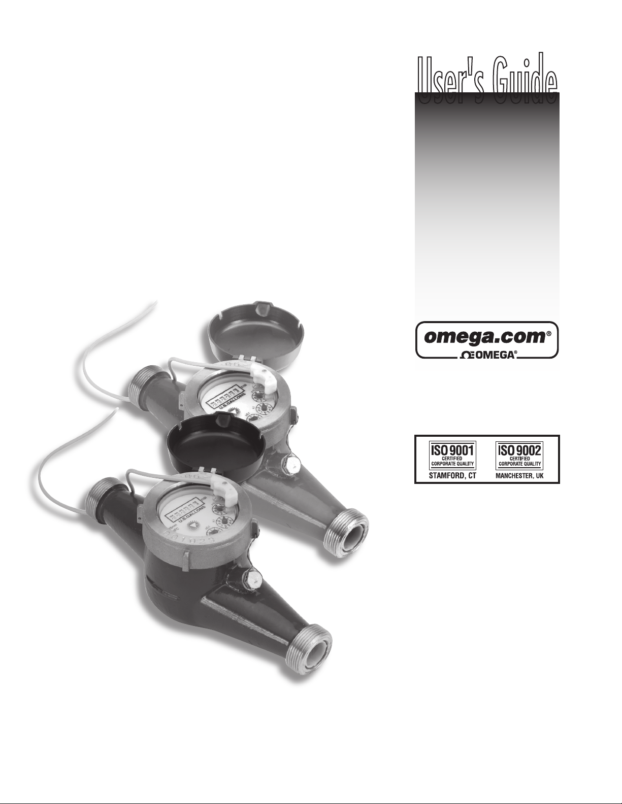
FTB8000B / FTB8000HW
Pulse Meter
Page 2

Servicing North America:
U.S.A.: One Omega Drive, P.O. Box 4047
ISO 9001 Certified
Stamford, CT 06907-0047
TEL: (203) 359-1660 FAX: (203) 359-7700
e-mail: [email protected]
Canada: 976 Bergar
Laval (Quebec) H7L 5A1, Canada
TEL: (514) 856-6928 FAX: (514) 856-6886
e-mail: [email protected]
For immediate technical or application assistance:
U.S.A. and Canada: Sales Service: 1-800-826-6342 / 1-800-TC-OMEGA
®
Customer Service: 1-800-622-2378 / 1-800-622-BEST
®
Engineering Service: 1-800-872-9436 / 1-800-USA-WHEN
®
TELEX: 996404 EASYLINK: 62968934 CABLE: OMEGA
Mexico: En Espan˜ol: (001) 203-359-7803 e-mail: [email protected]
FAX: (001) 203-359-7807 [email protected]
Servicing Europe:
Benelux: Postbus 8034, 1180 LA Amstelveen, The Netherlands
TEL: +31 (0)20 3472121 FAX: +31 (0)20 6434643
Toll Free in Benelux: 0800 0993344
e-mail: [email protected]
Czech Republic: Frystatska 184, 733 01 Karviná, Czech Republic
France: 11, rue Jacques Cartier, 78280 Guyancourt, France
TEL: +33 (0)1 61 37 2900 FAX: +33 (0)1 30 57 5427
Toll Free in France: 0800 466 342
e-mail: [email protected]
Germany/Austria: Daimlerstrasse 26, D-75392 Deckenpfronn, Germany
TEL: +49 (0)7056 9398-0 FAX: +49 (0)7056 9398-29
Toll Free in Germany: 0800 639 7678
e-mail: [email protected]
United Kingdom: One Omega Drive, River Bend Technology Centre
ISO 9002 Certified
Northbank, Irlam, Manchester
M44 5BD United Kingdom
TEL: +44 (0)161 777 6611 FAX: +44 (0)161 777 6622
Toll Free in United Kingdom: 0800-488-488
e-mail: [email protected]
OMEGAnet®Online Service Internet e-mail
omega.com i n f o @ o m e g a . c o m
It is the policy of OMEGA Engineering, Inc. to comply with all worldwide safety and EMC/EMI
regulations that apply. OMEGA is constantly pursuing certification of its products to the European New
Approach Directives. OMEGA will add the CE mark to every appropriate device upon certification.
The information contained in this document is believed to be correct, but OMEGA accepts no liability for any
errors it contains, and reserves the right to alter specifications without notice.
WARNING: These products are not designed for use in, and should not be used for, human applications.
Page 3

GENERAL INFORMATION, INSTALLATION and MAINTENANCE
GENERAL INFORMATION
FTB8000B (cold water) and FTB8000HW Series (hot water)
meters use the internationally-accepted multi-jet principle. A
gear train drives the register totalizer dials. For pulse output,
one of the pointers is replaced by a magnet arm, which is
detected by an encapsulated sensor attached to the outside
of the lens.
PR meters use a solid-state, long-lasting Hall-effect sensor,
which requires power. They are suited for use with Omega
controls and metering pumps (LMI for instance) that have
sensor power.
PT meters use a reed switch. They provide a dry contact closure and do not require power.
Standard meters do not have a sensor, and they totalize
only.
SPECIFICATIONS*
Power
Temperature
Cold Water
Hot Water
Pressure
Materials Body
Internals
Magnet
Accuracy
Pulse Output
Sensor
Max Current
Max Voltage
Cable Length
Flow Rates (GPM)
Minimum
**Maximum
*Specifications subject to change.
**CAUTION: Excessive ow can cause breakage.
Do not exceed recommended maximums.
6 mA at 12 Vdc (PR only)
105˚ F (40˚ C) max (8000B version)
194˚ F (90˚ C) max (8000HW version)
150 psi operating
Cast bronze, epoxy powder coated inside and out
Engineered thermoplastic
Alnico
+/- 1.5% of reading
PR PT Standard
Hall-effect Reed switch Totalizer only
20 mA 20 mA n/a
24 Vdc 24 Vdc or Vac n/a
12’ (4 m) standard (2000’ maximum run)
3/4” 1” 1-1/2” 2”
0.22 0.44 0.88 1.98
22 52 88 132
INSTALLATION
Position. FTB8000B and FTB8000HW Series meters should
be installed horizontally with the register up. Vertical mounting will result in some degree of under-measurement and
shortened life of the bearings. No upstream straight pipe is
required.
Caution: These water meters are
WARNING
DO NOT INSTALL
METER IN OVERHEAD
INDOOR PIPING OR
WHERE LEAKAGE
MAY CAUSE DAMAGE
not recommended for installation
in uninsulated suspended ceilings where freezing is possible,
or in any overhead indoor piping
conguration where leakage may
cause damage.
Couplings. Male NPT threaded couplings are included with
each meter. The threads on the end of the meter are IPS
straight threads one size bigger than the meter size. Though
it is possible to thread a standard pipe coupling directly onto
the meter for close coupling, the included couplings are much
preferable because they provide a union connection for meter
service. Be sure to use the included gasket between the end
of the meter and the coupling.
Connections. PR and PT sensors are supplied with a color
coded output cable (see diagram, page 4). Optional connectors can be ordered to plug directly into an Omega control or
LMI metering pump.
Pu lse Output. Both PR and PT sen sors respond to
a magnet that rotates on the face of the meter under
the lens. The sensor turns on and off once each time
the magnet passes under it. Sensors are designed for electronic control loads, and should not be used to switch power
loads or line voltages. See maximum current and voltage
ratings, under Specications.
MAINTENANCE
Omega recommends all service to be performed by an authorized distributor or the factory to maintain the integrity of the
protective tamper-proof wire-and-seal.
Inlet Strainer. Clean the strainer yearly, or as required, depending on water condition. Pull out the strainer or backush
the meter to loosen trapped particulates.
Calibration. Meters used for billing or billing exemp-
tion may be regulated by state or local authorities. New
me ters are fac tor y -tested to mee t the AWWA C-708
Mu lti-Jet Meter accuracy spe cif ication. Some states
require retesting at various intervals, typically eight years for
3/4" meters, six for 1", and four for 1-1/2" and 2". Meters
used for control should be tested every 5-10 years. Testing
can be done by the factory or local meter shops authorized
for this purpose. Please contact Omega before sending
meter in for calibration or servicing.
Page 2
Page 4
CHANGING PULSE RATES
Pulse
Rate
Magnet Pointer
Dial Position
Connection
Diagram #
*20 P/G 2
10 P/G 1
1
*2 P/G x0.1
x0.1
1 P /G x0.1
3/4"
*5 G/P x1 2
10 G/P x1 1
*50 G/P x10 2
100 G/P x10 1
*2 P/G x0.1 2
1"
1-1/2"
2"
1 P /G x0.1 1
*5 G/P x1 2
10 G/P x1 1
*50 G/P x10 2
100 G/P
x0.1
x0.1
1
*2 P/G 2
1 P /G 1
*5 G/P x1 2
10 G/P x1 1
*50 G/P x10 2
100 G/P
x0.1
x0.1
x0.1
1
*2 P/G
1 P /G
*5 G/P x1 2
10 G/P x1 1
*50 G/P
x10
x10
2
100 G/P x10 1
*The se pulse rate s available i n PT dual reed swi tch meter s only.
†Thi s pulse rate available in PT si ngle reed swi tch meter s only.
2
1
2
1
x0.01
x0.01
Meter
Size
†4 P/G
1
x0.1
†4 P/G
†4 P/G x0.1 1
†4 P/G 1
x10
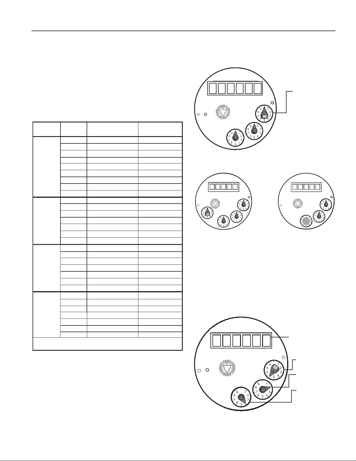
Setting Your Pulse Rate. The pulse rate is determined by which
sensor was ordered from the factory (single reed switch, dual
reed switch, or single Hall-effect) and by the dial on which the
magnet pointer is located. The pointer is set at the factory, but
can be changed in the eld as follows.
In the table below: 1) Locate your meter size (Column 1); 2)
Find your desired pulse rate (Column 2); 3) Note the magnet
pointer position (Column 3); 4) Move the magnet pointer to
the appropriate dial position (using the detailed instructions
below the table); 5) Use the appropriate Connection Diagram
(from Column 4) to wire the sensor to your remote device (using
diagrams on page 4).
Col. 1 Col. 2 Col. 3 Col. 4
Sample Set-Up. A 1” meter is shown with the magnet
pointer set at the x10 dial, with a pulse rate of 100 Gallons per Pulse (that is, 10 increments on the x10 dial, or
10x10=100 Gal/Pulse).
1” Meter
100 Gal/Pulse
25mm
40˚C
U.S. GALLONS
X1
X0.1
X100
X10
Magnet Pointer
x10 Dial
(10 x 10=100 G/P)
[With the magnet pointer
on the x1 dial, the pulse
rate would be 10x1=10
Gal/Pulse. With the magnet pointer on the x0.1
dial, the pulse rate would
be 10x.1=1 Gal/Pulse.]
Special Configurations.
X100
X10
X1
20mm
40˚C
X0.01
U.S. GALLONS
X0.1
X100
25mm
U.S. GALLONS
X10
X1
40˚C
X0.1
Moving the Magnetic Pointer. Remove meter top and lens,
taking care not to lose the sealing ring. With ngers, lift the
magnet pointer off its shaft and remove the plain pointer from
the target dial. Reverse their positions and press them rmly
into place. Securely seat the sealing ring and replace the lens,
matching the tab on the lens to the notch on the meter to align
the sensor with the magnetic pointer dial. Thread the meter top
on and tighten.
†NOTE: A special magnet (available from the factory) is required
to achieve a rate of 4 pulses per gallon. It should be placed on
the x0.1 dial, with non-magnetic pointers on the remaining dials.
Otherwise, the procedure is the same.
The 3/4” meter has a fourth dial,
as shown above. The x0.01 dial is
used for 20 P/G and 10 P/G rates.
Note: The 3/4” meter has a 5 digit
totalizer.
Reading Your Meter. The Total Flow that has passed
through your meter is read by starting at the top of the reg-
The 4 P/G rate requires
a special magnet, placed
on the x0.1 dial, as shown
above.
ister with the Six-Digit Totalizer, and then reading clockwise
around the small dials. In the example below, the Six-Digit
Totalizer reads 13,800 (138 x 100), and the dials read 60
(6 x 10), 2 (2 x 1), and .4 (4 x .1) respectively. The Total
Flow is 13,862.4 gallons.
1” Meter
100 Gal/Pulse
1 3 8
25mm
40˚C
(NOTE: Disregard the color of the numbers on the totalizer when reading your total.)
The “ones” digit is signicant but the fact that it is red is not signicant.
U.S. GALLONS
X1
X0.1
X100
X10
Six-Digit Totalizer
(reads 138x100)
x10 Gal Dial
(reads 6x10)
x1 Gal Dial
(reads 2x1)
x0.1 Gal Dial
(reads 4x0.1)
Page 3
Page 5
CONNECTIONS, MAINTENANCE and REPAIR
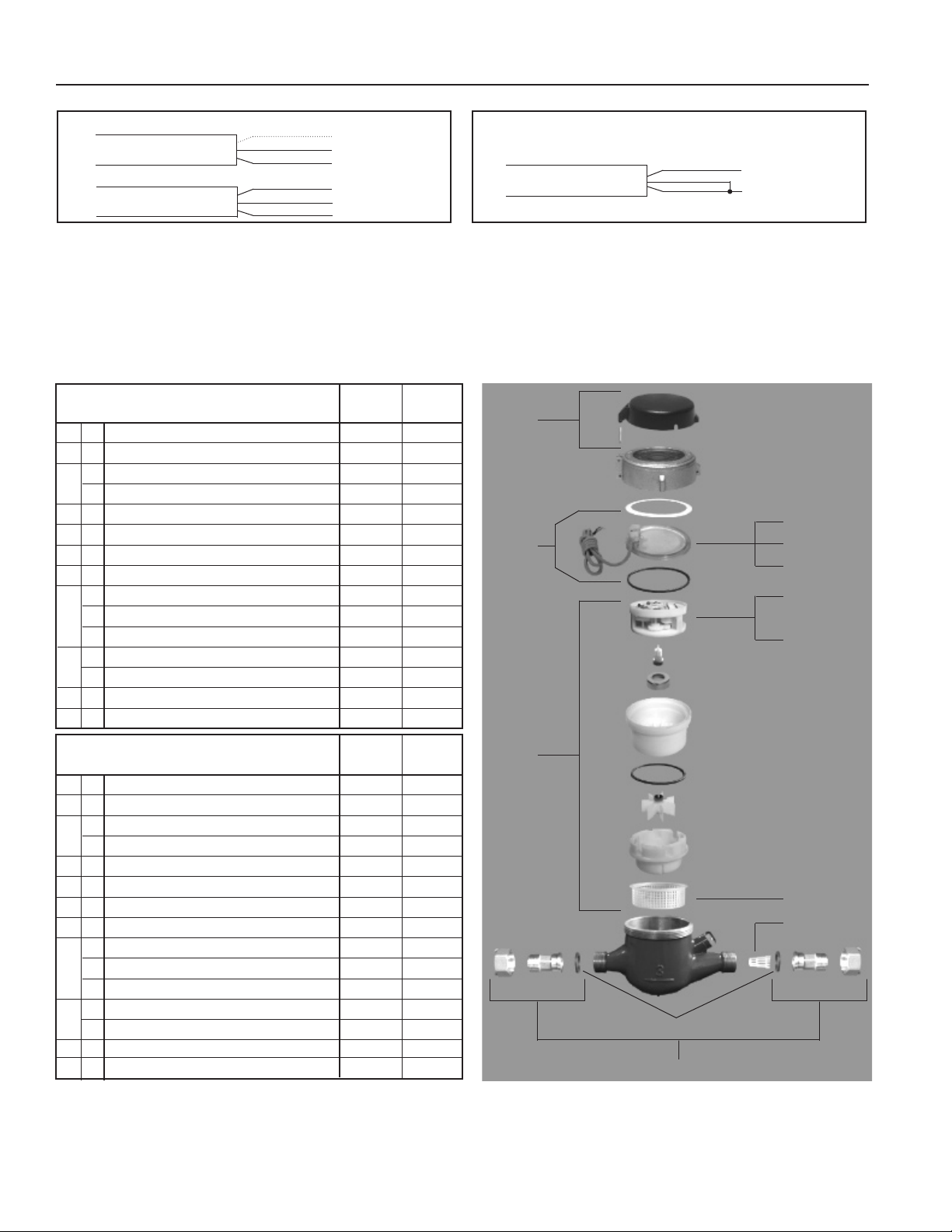
CONNECTION DIAGRAMS
Diagram 1: Single Sensor Diagram 2: Dual Sensor
Blue - (No Connection)
Black - Common
Red - N O
Black ( - )
White (signal)
Red (+)
PT:
Reed Switch
PR:
Hall-Effect
NOTE: The Dual Sensor is distinguished by a red stripe on the cable at
the base of the sensor.
NOTE: PR not available with dual sensor
Black - Common
Red - N O
Blue - N O
PT:
Reed Switch
To Distinguish Single Sensor From Dual:
Single: (if new from factory) blue wire is cut back on cable end.
Dual: A red stripe will be on cable near sensor.
INTERNAL PARTS REPLACEMENT. All of the internal parts
of an FTB8000B or FTB8000HW Series meter lift out as a
unit, after the top has been unscrewed. The lens can then
FTB8000B Series
1 Lid and Hinge Pin Assembly 31616 31617
2 Lens Gasket Assembly 31619 31620
a Internal Assembly (gallons) 31621 31622
3
b Internal Assembly (cubic feet) 31625 31626
4 Coupling Assembly (incl 2 sets) 32156 32157
5 Coupling Gasket Assembly (incl 2) 31629 31630
6 Lens 31471 31471
7 Sensor Screw 31519 31519
a Single Reed Switch Sensor (PT) 31444 31444
b Double Reed Switch Sensor (PT) 31457 314578
c Single Hall-Effect Sensor (PR) 31612 31612
a Register (gallons) 31463 31464
9
b Register (cubic feet) 31473 31474
10 Internal Strainer 31483 31517
11 Tubular Strainer 31496 31497
1 Lid and Hinge Pin Assembly 31618 31618
2 Lens Gasket Assembly 31633 31633
a Internal Assembly (gallons) 31623 31624
3
b Internal Assembly (cubic feet) 31627 31628
4 Coupling Assembly (incl 2 sets) 32158 32159
5 Coupling Gasket Assembly (incl 2) 31631 31632
6 Lens 31471 31471
7 Sensor Screw 31519 31519
a Single Reed Switch Sensor (PT) 31444 31444
b Double Reed Switch Sensor (PT) 31457 314578
c Single Hall-Effect Sensor (PR) 31612 31612
a Register (gallons) 31465 31466
9
b Register (cubic feet) 31475 31476
10 Internal Strainer 31518 31518
11 Tubular Strainer 31498 31499
Except as noted, individual parts are not available.
FTB8000B Series
3/4” 1”
1 1/2” 2”
Note: Dual sensor can be used as a single sensor also - use
either the red OR the blue wire w/black. If using it as a dual
sensor then connecting red and blue together will produce two
pulses with every revolution of magnet.
be removed and the internal assembly lifted out. If necessary, turn the meter upside down and tap one end lightly on
a countertop to loosen the internals. The assembly can be
separated by hand.
1
6
2
7
8 a-c
9a
or
9b
3a
or
3b
10
11
(includes 2)
5
(includes 2 sets)
4
Page 4
Page 6
CONNECTIONS, MAINTENANCE and REPAIR
®
,ENGINEERING
INC.
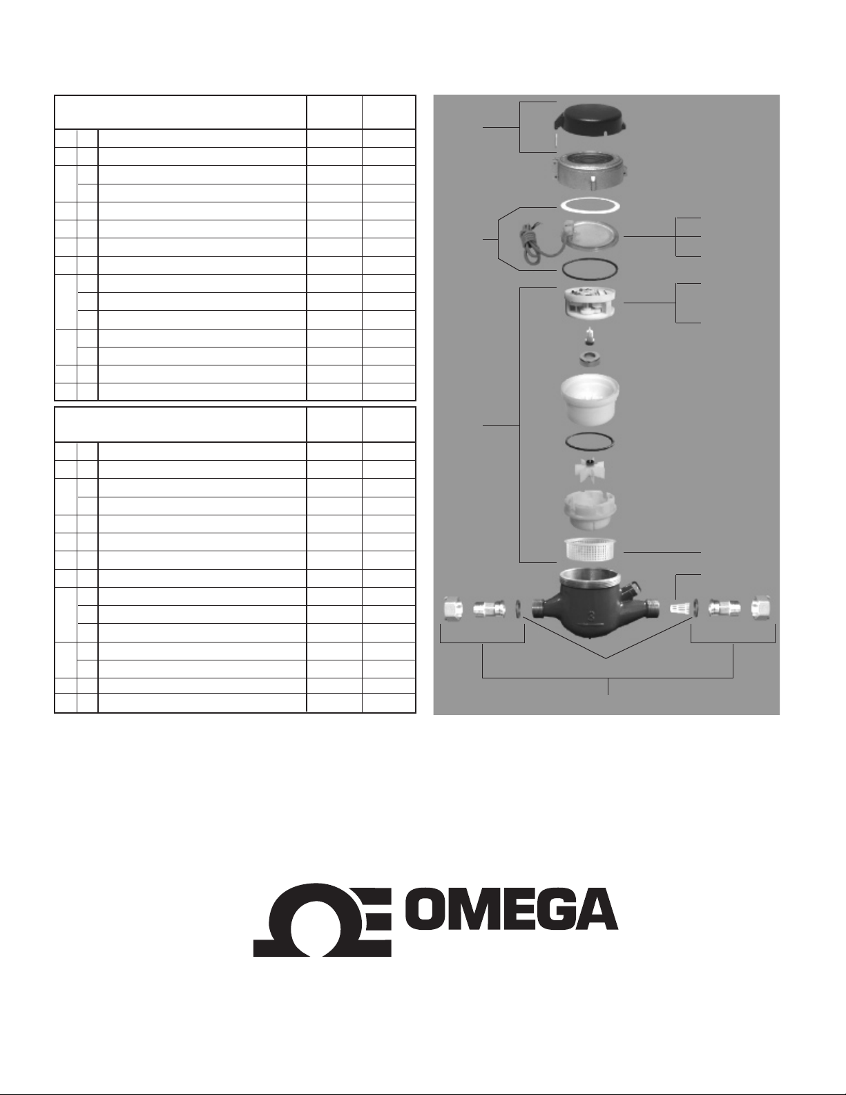
FTB8000HW Series
1 Lid and Hinge Pin Assembly 32241 32242
2 Lens Gasket Assembly 32219 32220
a Internal Assembly (gallons) 32237 32238
3
b Internal Assembly (cubic feet) 32233 32234
4 Coupling Assembly (incl 2 sets) 32215 32216
5 Coupling Gasket Assembly (incl 2) 32211 32212
6 Lens 31471 31471
7 Sensor Screw 31519 31519
a Single Reed Switch Sensor (PT) 31444 31444
b Double Reed Switch Sensor (PT) 31457 314578
c Single Hall-Effect Sensor (PR) 31612 31612
a Register (gallons) 32259 32260
9
b Register (cubic feet) 32255 32256
10 Internal Strainer 32266 32267
11 Tubular Strainer 32269 32270
1 Lid and Hinge Pin Assembly 32243 32243
2 Lens Gasket Assembly 32221 32221
a Internal Assembly (gallons) 32239 32240
3
b Internal Assembly (cubic feet) 32235 32236
4 Coupling Assembly (incl 2 sets) 32217 32218
5 Coupling Gasket Assembly (incl 2) 32213 32214
6 Lens 31471 31471
7 Sensor Screw 31519 31519
a Single Reed Switch Sensor (PT) 31444 31444
b Double Reed Switch Sensor (PT) 31457 314578
c Single Hall-Effect Sensor (PR) 31612 31612
a Register (gallons) 32261 32262
9
b Register (cubic feet) 32257 32258
10 Internal Strainer 32268 32268
11 Tubular Strainer 32271 32272
Except as noted, individual parts are not available.
FTB8000HW Series
3/4” 1”
1 1/2” 2”
3a
or
3b
1
6
2
7
8 a-c
9a
or
9b
10
11
(includes 2)
5
(includes 2 sets)
4
Page 5
Page 7

WARRANTY/DISCLAIMER
OMEGA ENGINEERING, INC. warrants this unit to be free of defects in materials and workmanship for a
period of 13 months f rom date of purchase. OMEGA’s WARRANTY adds an additional one (1) month
grace period to the normal one (1) year product warranty to cover handling and shipping time. This
ensures that OMEGA’s customers receive maximum coverage on each product.
If the unit malfunctions, it must be re t u rned to the factory for evaluation. O M E G A’s Customer Serv i c e
D e p a rtment will issue an Authorized Return (AR) number immediately upon phone or written re q u e s t .
Upon examination by OMEGA, if the unit is found to be defective, it will be re p a i red or replaced at no
c h a rge. O M E G A’s WARRANTY does not apply to defects resulting from any action of the purc h a s e r,
including but not limited to mishandling, improper interfacing, operation outside of design limits,
i m p roper re p a i r, or unauthorized modification. This WARRANTY is VOID if the unit shows evidence of
having been tampered with or shows evidence of having been damaged as a result of excessive corro s i o n ;
or current, heat, moisture or vibration; improper specification; misapplication; misuse or other operating
conditions outside of OMEGA’s c o n t rol. Components in which wear is not warranted, include but are not
limited to contact points, fuses, and triacs.
OMEGA is pleased to offer suggestions on the use of its various products. However,
OMEGA neither assumes responsibility for any omissions or errors nor assumes liability for any
damages that result from the use of its products in accordance with information provided by
OMEGA, either verbal or written. OMEGA warrants only that the parts manufactured by the
company will be as specified and free of defects. OMEGA MAKES NO OTHER WARRANTIES OR
R E P R E S E N TATIONS OF ANY KIND WHATSOEVER, EXPRESSED OR IMPLIED, EXCEPT THAT OF
TITLE, AND ALL IMPLIED WARRANTIES INCLUDING ANY WARRANTY OF MERCHANTA B I L I T Y
AND FITNESS FOR A PA RTICULAR PURPOSE ARE HEREBY DISCLAIMED. LIMITATION OF
L I A B I L I T Y: The remedies of purchaser set forth herein are exclusive, and the total liability of
OMEGA with respect to this ord e r, whether based on contract, warr a n t y, negligence,
indemnification, strict liability or otherwise, shall not exceed the purchase price of the
compone nt upo n which liability is based . In no e vent s hall OMEGA b e lia ble for
consequential, incidental or special damages.
CONDITIONS: Equipment sold by OMEGA is not intended to be used, nor shall it be used: (1) as a “Basic
Component” under 10 CFR 21 (NRC), used in or with any nuclear installation or activity; or (2) in medical
applications or used on humans. Should any Product(s) be used in or with any nuclear installation or
a c t i v i t y, medical application, used on humans, or misused in any way, OMEGA assumes no re s p o n s i b i l i t y
as set forth in our basic WA R R A N TY/ DISCLAIMER language, and, additionally, purchaser will indemnify
OMEGA and hold OMEGA h a rmless from any liability or damage whatsoever arising out of the use of the
P roduct(s) in such a manner.
RETURN REQUESTS/INQUIRIES
Direct all warranty and repair requests/inquiries to the OMEGA Customer Service Department. BEFORE
RETURNING ANY PRODUCT(S) TO OMEGA, PURCHASER MUST OBTAIN AN AUTHORIZED RETURN
(AR ) NU M BER F ROM O MEGA’ S CU STOM E R SE RV I CE DEPA RTMEN T (I N OR DER T O AV O I D
PROCESSING DELAYS). The assigned AR number should then be marked on the outside of the return
package and on any correspondence.
The purchaser is responsible for shipping charges, freight, insurance and proper packaging to prevent
breakage in transit.
FOR WARRANTY RETURNS, please have the
following information available BEFORE
contacting OMEGA:
1 . P u rchase Order number under which the pro d u c t
was PURCHASED,
2. Model and serial number of the product under
warranty, and
3. Repair instructions and/or specific problems
relative to the product.
FOR NON-WARRANTY REPAIRS,
consult OMEGA
for current repair charges. Have the following
information available BEFORE contacting OMEGA:
1. Purchase Order number to cover the COST
of the repair,
2. Model and serial number of the product, and
3. Repair instructions and/or specific problems
relative to the product.
OMEGA’s policy is to make running changes, not model changes, whenever an improvement is possible. This affords
our customers the latest in technology and engineering.
OMEGA is a registered trademark of OMEGA ENGINEERING, INC.
© Copyright 2005 OMEGA ENGINEERING, INC. All rights reserved. This document may not be copied, photocopied,
reproduced, translated, or reduced to any electronic medium or machine-readable form, in whole or in part, without the
prior written consent of OMEGA ENGINEERING, INC.
Page 8

W h e re Do I Find Eve rything I Need for
P rocess Measurement and Control?
OME GA…Of Cours e !
Shop online at omega.com
T E M P E R AT U R E
Thermocouple, RTD & Thermistor Probes, Connectors, Panels & Assemblies
Wire: Thermocouple, RTD & Thermistor
Calibrators & Ice Point References
Recorders, Controllers & Process Monitors
Infrared Pyrometers
PRESSURE, STRAIN AND FO RC E
Transducers & Strain Gages
Load Cells & Pressure Gages
Displacement Transducers
Instrumentation & Accessories
F LOW / L E V E L
Rotameters, Gas Mass Flowmeters & Flow Computers
Air Velocity Indicators
Turbine/Paddlewheel Systems
Totalizers & Batch Controllers
p H / C O N D U C T I V I TY
pH Electrodes, Testers & Accessories
Benchtop/Laboratory Meters
Controllers, Calibrators, Simulators & Pumps
Industrial pH & Conductivity Equipment
DATA AC Q U I S I T I O N
Data Acquisition & Engineering Software
Communications-Based Acquisition Systems
Plug-in Cards for Apple, IBM & Compatibles
Datalogging Systems
Recorders, Printers & Plotters
H E AT E R S
Heating Cable
Cartridge & Strip Heaters
Immersion & Band Heaters
Flexible Heaters
Laboratory Heaters
E N V I RO N M E N TA L
M O N I TORING AND CONTRO L
Metering & Control Instrumentation
R e f r a c t o m e t e r s
Pumps & Tubing
Air, Soil & Water Monitors
Industrial Water & Wastewater Treatment
pH, Conductivity & Dissolved Oxygen Instruments
PL-OM-65200212-D
3/24/11
M-4373/0311
 Loading...