

Page 1
TM
User’s Guide
Shop online at
omega.com
e-mail: [email protected]
For latest product manuals:
omega.com/en-us/pdf-manuals
8
00
Page 2

omega.com [email protected]
Servicing North America:
U.S.A.
Headquarters:
800 Connecticut Ave. Suite 5N01, Norwalk, CT 06854
Customer Service: 1-800-622-2378 (USA & Canada only)
Engineering Service: 1-800-872-9436 (USA & Canada only)
Tel: (203) 359-1660 Fax: (203) 359-7700
e-mail: [email protected]
Omega Engineering, Inc.
Toll-Free: 1-800-826-6342 (USA & Canada only)
The information contained in this document is believed to be correct, but OMEGA accepts no liability for any errors it contains, and
reserves the right to alter specifications without notice.
Page 3

GENERAL DESCRIPTION
1.1 Working Principle
When liquid flows through the casing of sensor, the impulse of fluid will provide the
blade with a rotation moment as there is an angle between the blade of impeller and
the flow direction. The blade will rotate as the friction moment and the fluid
resistance are overcome and it will reach a stable speed when the moments are at
balance. Under certain conditions, the rotation speed of blade will be in direct
proportion to the flow velocity. Due to the magnetic conductivity of blade, when
located in the magnetic field generated by signal detector (made of permanent magnet
steel and coils), the rotating blade will cut the magnetic lines and periodically change
the flux through the coil, thereby inducing electrical impulse signals at both ends of
the coil. The induced signals, after amplified and rectified by amplifier, will form a
continuous rectangular impulse wave with certain amplitude which may be remotely
transmitted to display instrument indicating the instant flow and the cumulative flow
of fluid. Within a certain range of flow, the impulse frequency f is in direct proportion
to the instant flow of fluid flowing through the sensor.
FEATURES
1. The sensor is of hard alloy bearing thrust type, which may guarantee the precision
and improve the wear resistance performance as well.
2.Simple and firm structure, easy for installation and dismantling.
3.Wide range of measuring with very low lower flow velocity limit.
4.Small loss of pressure,fine repeat ability and high precision.
5.High resistance to electromagnetic interference and vibration.
SPECIFICATIONS
MATERIALS OF CONSTRUCTION:
Body: 304 OR 316 Stainless Steel
Rotor: CD4MCU Stainless Steel
Rotor Support and Bearing: 316 Stainless Steel
Rotor Shaft: Tungsten Carbide
OPERATING LIMITATIONS:
Temperature: -20°C to +120°C High temperatures will damage the magnetic pick-up,
while lower temperatures will limit the rotation of the rotor.
Pressure: Maximum pressure ratings as follows:
913.5 psi ─ all NPT meters up to 1"
362.5 psi ─ 1-1/4”,1-1/2”,2" male NPT
Page 4
232 psi ─ 2-1/2”,3”,4” male NPT
WARNING: Pressure in excess of allowable rating may cause the housing to burst
and cause serious personal injury.
Accuracy: ± 0.5% of reading
Repeatability: ± 0.1%
Calibration: Water (CNAS Traceable Calibration)
Corrosion: All FTB-800 series turbine meters are constructed of stainless steel and
CD4MCU. The operator must ensure that the operating fluid is compatible with these
materials. Incompatible fluids can cause deterioration of internal components and
cause a reduction in meter accuracy.
Pulsation and
Vibration: Severe pulsation and mechanical vibration will affect accuracy and
shorten the life of the meter
Filtration: If small particles are present in the fluid, it is recommended that a strainer
be installed upstream of the meter
Output: 4 to 20mA output
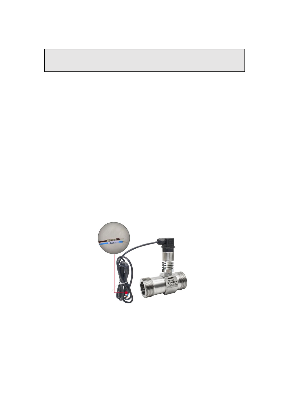
Two wires from the flow sensor, 24V+ and 24V-, connect other instrument which can
supply 24VDC.
Page 5
Overall Dimension
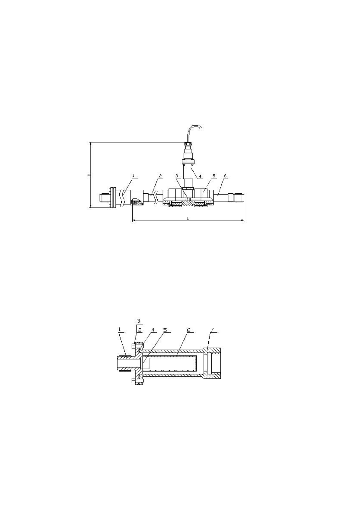
The installation typesof sensors vary according tospecifications, w h i c h maybe
connected either by thread or flange. The installation typesa r e shown inF i g . 1, F i g . 2,
Fig.3, F i g . 4 a n d F i g . 5. The installation dimensions a r e shown inT a b l e 2.
F i g . 1 Structure of DN4mm~DN10mm sensor a n d installation dimension diagram
Filter 2. Front straight pipe section 3. Impeller 4. Preamplifier 5. Casing6. Rear
straight pipe section
F i g . 2 Filter structure diagram
Clamp r i n g 2. Bolts 4×14 3. W a s h e r 4. Sealing washer 5. Steel w i r e
1Cr18Ni9Ti-0.8×2.5 6. Filter screen 7. B a s e
Page 6
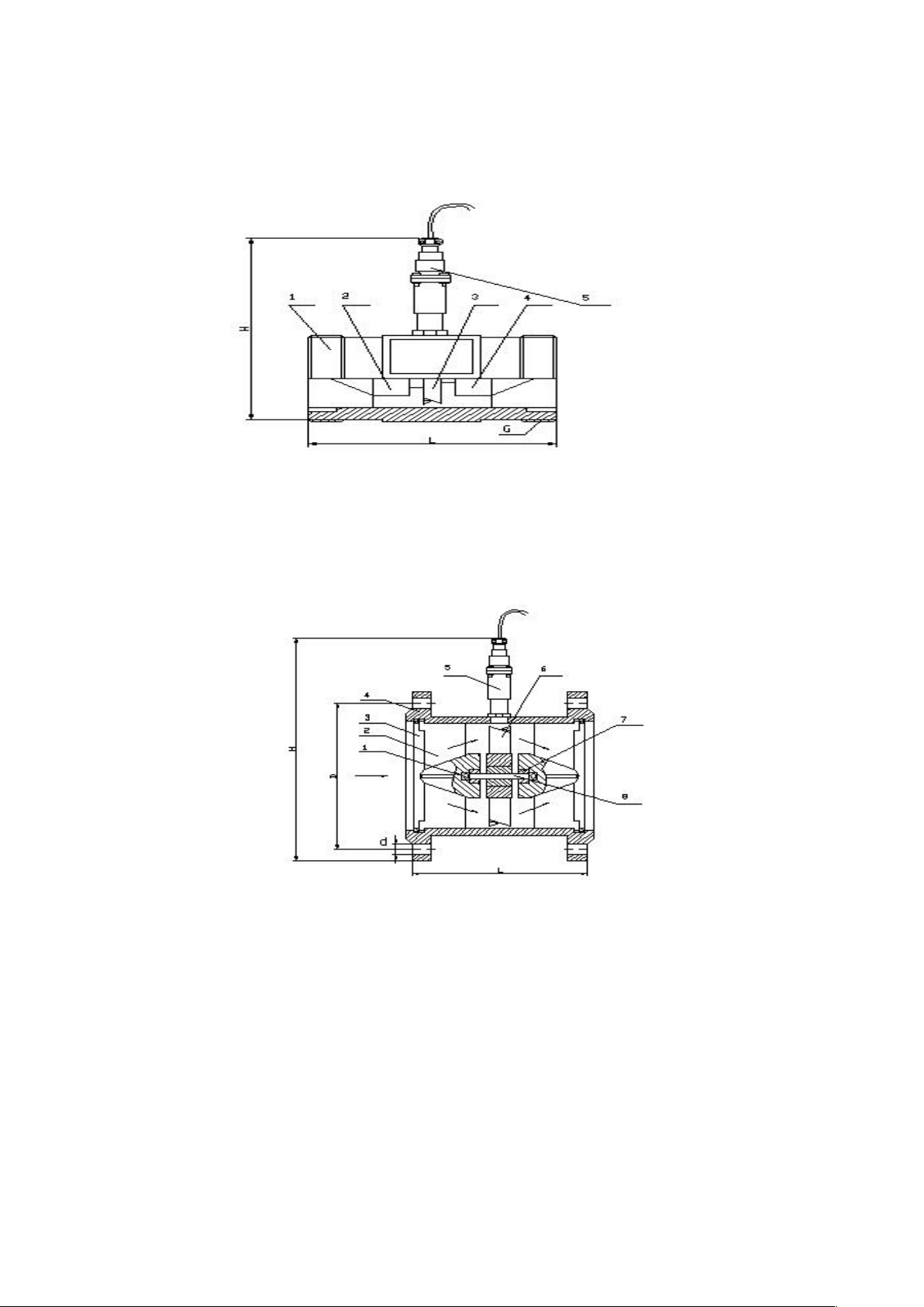
Fig. 3 Structure of DN15mm~DN40mm sensor and installation dimension diagram
Casing 2.Front guide part 3.Impeller 4.Rear guide part 5.Preamplifier
Fig. 4 Structure of DN50mm~200mm sensor and installation dimension diagram
Ball bearing 2.Front guide part 3.Expansion ring 4.Casing 5.Preamplifier
6.Impeller 7.Bearing 8.Shaft
Installation Requirements
Flow meter may be installed horizontally or vertically. In the latter case the fluid shall
be flowing from downward and fulfill the pipe to avoid bubbles; the flowing direction
of liquid shall be consistent with the direction indicated by the arrow on casing of the
sensor; as far as front and rear straight pipe sections are concerned (see Fig. 6), at
Page 7
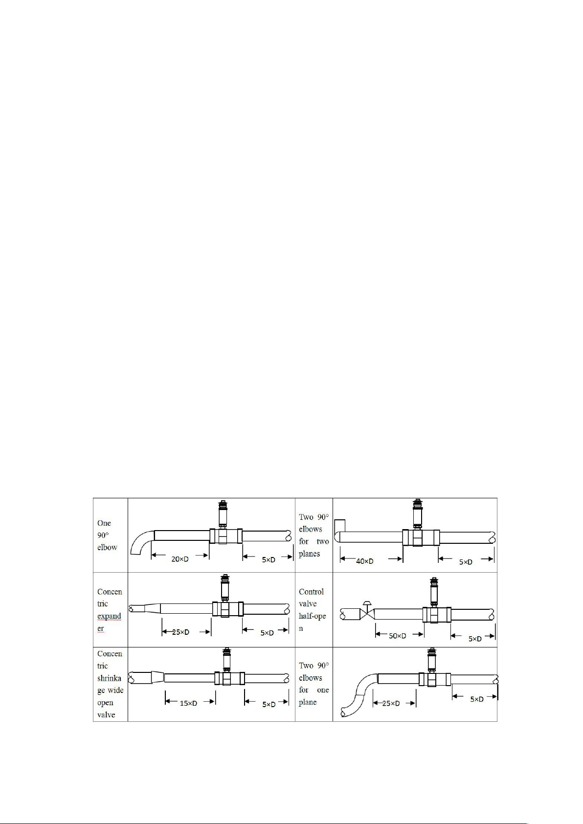
upstream there shall be front straight pipe section at least 10 times of nominal drift
diameter in length and at downstream no less than 5 times of nominal drift diameter in
length. The internal wall of pipe sections shall be smooth and clean, free of defects
such as indent, fouling and peeling. The pipe axis of the sensor shall be aligned with
that of the neighboring pipe and the washers used for connection and sealing may not
be embedded into depth of the pipe cavity; the sensors shall be kept away from
foreign electric field and magnetic
field, effective shielding measures shall be taken in case of necessity to avoid external
interference.
In order that the normal transfer of liquid will not be affected by maintenance, it is
recommended that bypass pipes be installed at position of sensor.
In case of open air installation, water proof measures shall be taken for purpose of
amplifier and plug of the sensor. The wiring between sensor and display instrument is
shown in Fig. 5.
When fluid contains impurities, filter shall be additionally installed. The number of
filter screen meshes is determined in accordance with the flow and impurity, normally
20 to 60 meshes. When fluid is mixed with free gases, gas eliminator shall be
additionally installed. The complete pipe system shall be well sealed. The user shall
fully understand the erosion nature of the measured medium to protect the sensor
from being eroded.
Fig. 6 Requirements on straight pipe section for installation of flow meter
Page 8

Operation
◆ When sensor is used, the liquid to be measured shall be clean and free of
impurities such as fiber and granules.
◆ When sensor is used, it shall be at first slowly filled with liquid, then open the
outlet valve (which should be installed behind the flow meter). It is prohibited to
render the sensor under impact of high-velocity fluid when it is not filled with liquid.
◆ The maintenance interval for sensor is in general half a year. In case of
maintenance and cleaning, attention shall be paid not to damage the parts in the
measuring cavity, particularly the impeller. During assembly, watch carefully the
positional relation between guide part and impeller.
◆ When the sensor will be out of service for a long time, the internal liquid shall be
cleaned. After dried, the sensor shall be provided with protection sleeves at both ends
to protect against dust and it shall be placed in dry conditions for storage.
◆ The associated filter shall be cleaned on regular basis and the internal
liquid shall be cleaned when it is out of service for a long time. Similar to sensor, the
filter shall also be provided with dust protection and stored in dry conditions.
◆ The transmission wire of sensor may be overhead or buried (iron bushing shall be
provided in the latter case).
◆ Prior to installation of sensor, the connection thereof with display instrument or
oscilloscope shall be finished. Then switch on the power, blow the impeller or move
the impeller with hand to make it rotate quickly, see if there is any reading. Install the
sensor if there is reading. In case of no reading, the related sections shall be inspected
to eliminate any fault.
Page 9

WARRANTY/DISCLAIMER
OMEGA ENGINEERING, INC. warrants this unit to be free of defects in materials and workmanship
for a period of 13 months from date of purchase. OMEGA’s WARRANTY adds an additional one (1)
month grace period to the normal one (1) year product warranty to cover handling and shipping
time. This ensures that OMEGA’s customers receive maximum coverage on each product.
If the unit malfunctions, it must be returned to the factory for evaluation. OMEGA’s Customer Service
Department will issue an Authorized Return (AR) number immediately upon phone or written request.
Upon examination by OMEGA, if the unit is found to be defective, it will be repaired or replaced at no
charge. OMEGA’s WARRANTY does not apply to defects resulting from any action of the purchaser,
including but not limited to mishandling, improper interfacing, operation outside of design limits,
improper repair, or unauthorized modification. This WARRANTY is VOID if the unit shows evidence of
having been tampered with or shows evidence of having been damaged as a
result of excessive corrosion; or current, heat, moisture or vibration; improper
specification; misapplication; misuse or other operating conditions outside of
OMEGA’s control. Components in which wear is not warranted, include but are not
limited to contact points, fuses, and triacs.
OMEGA is pleased to offer suggestions on the use of its various products. However,
OMEGA neither assumes responsibility for any omissions or errors nor
assumes liability for any damages that result from the use of its products
in accordance with information provided by OMEGA, either verbal or
written. OMEGA warrants only that the parts manufactured by it will be as
specified and free of defects. OMEGA MAKES NO OTHER WARRANTIES OR
REPRESENTATIONS OF ANY KIND WHATSOEVER, EXPRESS OR IMPLIED, EXCEPT
THAT OF TITLE, AND ALL IMPLIED WARRANTIES INCLUDING ANY WARRANTY OF
MERCHANTABILITY AND FITNESS FOR A PARTICULAR PURPOSE ARE HEREBY
DISCLAIMED. LIMITATION OF LIABILITY: The remedies of purchaser set forth herein are
exclusive, and the total liability of OMEGA with respect to this order, whether
based on contract, warranty, negligence, indemnification, strict liability or otherwise,
shall not exceed the purchase price of the component upon which liability
is based. In no event shall OMEGA be liable for consequential, incidental or special damages.
CONDITIONS: Equipment sold by OMEGA is not intended to be used, nor shall it be used: (1) as a
“Basic Component” under 10 CFR 21 (NRC), used in or with any nuclear installation or activity; or (2)
in medical applications or used on humans. Should any Product(s) be used in or with any nuclear
installation or activity, medical application, used on humans, or misused in any way, OMEGA assumes
no responsibility as set forth in our basic WARRANTY / DISCLAIMER language, and, additionally,
purchaser will indemnify OMEGA and hold OMEGA harmless from any liability or damage whatsoever
arising out of the use of the Product(s) in such a manner.
RETURN REQUESTS/INQUIRIES
Direct all warranty and repair requests/inquiries to the OMEGA Customer Service Department.
BEFORE RETURNING ANY PRODUCT(S) TO OMEGA, PURCHASER MUST OBTAIN AN AUTHORIZED
RETURN (AR) NUMBER FROM OMEGA’S CUSTOMER SERVICE DEPARTMENT (IN ORDER TO AVOID
PROCESSING DELAYS). The assigned AR number should then be marked on the outside of the return
package and on any correspondence.
The purchaser is responsible for shipping charges, freight, insurance and proper packaging to prevent
breakage in transit.
FOR WARRANTY RETURNS, please have the
following information available BEFORE
contacting OMEGA:
1. Purchase Order number under which the
product was PURCHASED,
2. Model and serial number of the product under
warranty, and
3. Repair instructions and/or specific problems
relative to the product.
OMEGA’s policy is to make running changes, not model changes, whenever an improvement is possible. This affords
our customers the latest in technology and engineering.
OMEGA is a trademark of OMEGA ENGINEERING, INC.
© Copyright 2019 OMEGA ENGINEERING, INC. All rights reserved. This document may not be copied, photocopied,
reproduced, translated, or reduced to any electronic medium or machine-readable form, in whole or in part, without the
prior written consent of OMEGA ENGINEERING, INC.
FOR NON-WARRANTY REPAIRS,
for current repair charges. Have the following
information available BEFORE contacting OMEGA:
1. Purchase Order number to cover the COST
of the repair,
2. Model and serial number of the product, and
3. Repair instructions and/or specific problems
relative to the product.
consult OMEGA
Page 10

Where Do I Find Everything I Need for
Process Measurement and Control?
OMEGA…Of Course!
Shop online at omega.com
TEMPERATURE
MU
Thermocouple, RTD & Thermistor Probes, Connectors, Panels & Assemblies
MU
Wire: Thermocouple, RTD & Thermistor
MU
Calibrators & Ice Point References
MU
Recorders, Controllers & Process Monitors
MU
Infrared Pyrometers
PRESSURE, STRAIN AND FORCE
MU
Transducers & Strain Gages
MU
Load Cells & Pressure Gages
MU
Displacement Transducers
MU
Instrumentation & Accessories
FLOW/LEVEL
MU
Rotameters, Gas Mass Flowmeters & Flow Computers
MU
Air Velocity Indicators
MU
Turbine/Paddlewheel Systems
MU
Totalizers & Batch Controllers
pH/CONDUCTIVITY
MU
pH Electrodes, Testers & Accessories
MU
Benchtop/Laboratory Meters
MU
Controllers, Calibrators, Simulators & Pumps
MU
Industrial pH & Conductivity Equipment
DATA ACQUISITION
MU Communications-Based Acquisition Systems
MU Data Logging Systems
MU Wireless Sensors, Transmitters, & Receivers
MU Signal Conditioners
MU Data Acquisition Software
HEATERS
MU
Heating Cable
MU
Cartridge & Strip Heaters
MU
Immersion & Band Heaters
MU
Flexible Heaters
MU
Laboratory Heaters
ENVIRONMENTAL
MONITORING AND CONTROL
MU
Metering & Control Instrumentation
MU
Refractometers
MU
Pumps & Tubing
MU
Air, Soil & Water Monitors
MU
Industrial Water & Wastewater Treatment
MU
pH, Conductivity & Dissolved Oxygen Instruments
M5765/0420
 Loading...