

Page 1

Page 2

Page 3
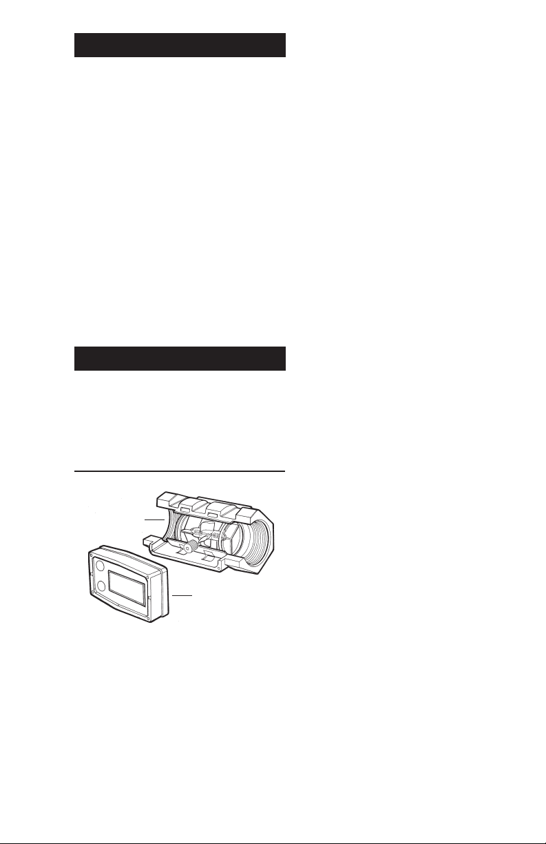
TABLE OF CONTENTS
General Information .................................... 1
Product Description .................................... 2
Installation ...................................................2
Connections .................................................3
Operations ................................................... 4
Calibration ...................................................5
Maintenance ................................................ 8
Replacing the Batteries ............................... 9
Troubleshooting ........................................ 10
Specications ............................................ 11
Model Numbers ........................................ 16
Parts & Accessories ................................... 18
Warranty/Disclaimer ................................. 19
Return Requests/Inquiries ......................... 19
GENERAL INFORMATION
This manual will assist you in installing and
maintaining your FTB790 Series turbine meter
and associated display electronics. The turbine
meters can be purchased with or without the
display electronics. (See Figure 1)
Figure 1
Turbine Housing
Display Electronics
When purchased with the display electronics,
optional accessory modules are available for
eld installation. Information on these accessories is contained in separate manuals. Calibration details using the display electronics
are given in this manual.
When purchased without the display (Sufx ND) an optional eld installable Pulse Output
Module (FLSC790-P-ND) is available and
described in a separate manual.
For best results, take the time to fully acquaint yourself with all information about all
components of your FTB790 Series Turbine
Meter System prior to installation and use. If
you need assistance, contact the Omega Flow
Application Department.
This symbol is used throughout the
!
manual to call your attention to safety
▲
messages.
Warnings alert you to the potential for per-
sonal injury.
Cautions call your attention to practices or
procedures which may damage your
equipment.
Notes give information that can improve
efciency of operations.
It is your responsibility to make sure that all
operators have access to adequate instructions about safe operating and maintenance
procedures.
Read Me!
For your safety, review the major warnings
and cautions below before operating your
equipment.
1. This equipment is approved to handle only
uids which are compatible with all wetted
materials.
2. When measuring ammable liquids, ob serve precautions against re or explosion.
3. When handling hazardous liquids, always
follow the liquid manufacturer ’s safety
precautions.
4. When working in hazardous environments,
always exercise appropriate safety precautions.
5. Always dispose of used cleaning solvents
in a safe manner according to the solvent
manufacturer’s instructions.
6. During turbine removal, liquid may spill.
Follow the liquid manufacturer’s safety
precautions for clean up of minor spills.
7. Do not blow compressed air through the
turbine.
8. Do not allow liquids to dry inside the
turbine.
1
Page 4

9. Handle the rotor carefully. Even small
scratches or nicks can affect accuracy.
10. When tightening the turbine, use a wrench
only on the wrench ats.
11. For best results, always verify accuracy
before use.
PRODUCT DESCRIPTION
FTB790 Series Turbines are identied by the
internal diameter of the inlet and outlet.
FTB791 – 1/2 inch (Mid Flow)
FTB792 – 3/4 inch (Mid Flow)
FTB793 – 1 inch (Mid Flow)
FTB794 – 1-1/2 inch (High Flow)
FTB795 – 2 inch (High Flow)
Each of these turbines are designed to work
with on-board display electronics and/or with
one of several accessory modules that can
interface to a wide variety of reporting and
collecting devices.
The CMOS microprocessor-based electronics
have extremely low power requirements and
data retention capabilities in both RAM and
ROM. Information is clearly displayed on
a large 6-digit LCD readout with two-point
oating decimal for totals from .01 to 999,999.
All operations are easily accessed with the two
buttons on the front panel.
Liquids flow through the turbine housing
causing an internal rotor to spin. As the rotor
spins, an electrical signal is generated in the
pickup coil. The electrical signal provides
the output necessary to operate the on-board
display electronics for local indication directly
on the turbine or one of several accessory
modules that transmit the signal to external
equipment.
Upon receipt, examine your meter for visible
damage. The turbine is a precision measuring
instrument and should be handled as such.
Remove the protective plugs and caps for
a thorough inspection. If any items are damaged or missing, contact OMEGA Customer
Service.
Make sure the turbine model meets your spe-
cic needs. Refer to the Specications Section
and conrm the following:
1. The owrate is within the limits of your
model.
2. The liquid is compatible with the turbine’s
wetted components.
3. The system’s pressure does not exceed
the turbine’s maximum pressure rating.
Information specic to your particular turbine,
including serial number, model number,
manufacturing date, and K-factor is etched
into the surface of the turbine. On Models
FTB791, FTB792, and FTB793 find the
etched information on the side of the turbine.
On Models FTB794 and FTB795 the informa-
tion is etched on a wrench at.
SN = Serial Number, a 7-8 digit number that
identies this particular turbine.
MOD = Model number.
KF = K‑Factor given in pulses per gallon
(PPG).
MFD = Manufacturing Date indicating the
week and year of manufacture.
For your future reference, it might be useful to
record this information in the manual in case
it becomes unreadable on the turbine.
INSTALLATION
All Series FTB790 turbines are designed to
measure ow in only one direction. The direction is indicated by the arrow cast-molded in
the turbine outlet. If the opposite direction is
desired, and you are using on-board display
electronics, rotate the display electronics 180
degrees prior to installation.
Flow altering devices such as elbows, valves,
and reducers can affect accuracy. The following recommended guidelines are given to
enhance accuracy and maximize performance.
Distances given here are minimum requirements; double them for desired straight pipe
lengths.
Upstream from the turbine, allow a minimum
straight pipe length at least 10 times the in-
ternal diameter of the turbine. For example,
with the FTB793 turbine, there should be 10
inches (25.4cm) of straight pipe immediately
upstream. The desired upstream straight pipe
length is 20 inches (50.8cm).
2
Page 5

Downstream from the turbine, allow a minimum straight pipe length at least 5 times the
internal diameter of your turbine. For example, with the FTB793 turbine, there should
be 5 inches (12.7cm) of straight pipe immediately downstream. The desired downstream
distance is 10 inches (25.4cm).
A typical back pressure of 5 to 50 PSI (0.34 to
3.4 bar) will prevent cavitation. Create back
pressure by installing a control valve on the
downstream side of the meter at the proper
distance detailed above.
Foreign material in the liquid being measured
can clog the turbine’s rotor and adversely affect accuracy. If this problem is anticipated or
experienced, install screens to lter impurities
from incoming liquids.
Models FTB791, FTB792, FTB793
Maximum Particulate Size
Inches: 0.005
Microns: 125
Mesh: 55
Standard Sieve: 125 µm
Alternative Sieve: No. 120
Models FTB794 and FTB795
Maximum Particulate Size
Inches: 0.018
Microns: 500
Mesh: 28
Standard Sieve: 500 µm
Alternative Sieve: No. 35
All Series FTB790 turbines are Factory Mutual Approved and carry a Class 1, Division 1
Approval for hazardous environments. They
are tested and calibrated at the factory using
state-of-the-art calibration procedures and
test equipment.
To ensure accurate measurement, remove all
air from the system before use. To purge the
system of air:
1. Ensure some back pressure on the turbine.
2. Open the discharge valve or nozzle and
allow uid to completely ll the system.
Make sure the stream is full and steady.
3. Close the discharge valve or nozzle.
4. Start normal operations.
Each turbine contains a removable back coverplate. Leave the coverplate installed unless
accessory modules specify removal.
CONNECTIONS
1. To protect against leakage, seal all threads
with an appropriate sealing compound.
Make sure the sealing compound does
not intrude into the ow path.
2. Make sure the arrow on the outlet is
pointed in the direction of the ow.
3. Tighten the turbine onto the ttings. Use
a wrench only on wrench ats.
NOTE: If connecting to new male threads,
burrs and curls can adversely effect
accuracy. Correct the problem prior to
turbine installation.
It is strongly recommended that accuracy be
veried prior to use. To do this, remove all
air from the system, measure an exact known
volume into an accurate container, and verify
the volume against the readout or recording
equipment. If necessary, use a correction
factor to gure nal volume. For best results,
accuracy should be veried periodically as
part of a routine maintenance schedule.
The display electronics is normally installed
on the turbine housing at the factory unless
ordered without it.
If for any reason the display electronics
need to be mounted on your turbine, simply
mount the display on the turbine with the four
screws at the corners of the faceplate. Make
sure the seal is fully seated before tightening
the screws.
If you ordered the FTB790 Series turbine with
an accessory module, please review and thoroughly understand all installation instructions
before proceeding.
Avoid electronically “noisy” environments.
Install at least 6 inches (15.2cm) away from
motors, relays, or transformers.
3
Page 6
OPERATIONS
All operations are reected in the LCD readout. The top line identies the calibration
curve. The middle line reects ow informa-
tion. The bottom line shows information from
the totalizer. Words or “ags” display on the
top and bottom line to further identify specic
information.
The display electronics is powered by eld
replaceable batteries. When the readout becomes dim or faded, the batteries need to be
replaced. Reference the Maintenance Section
for details.
NOTE: Operations can be practiced prior to
installation. To simulate ow conditions,
blow gently through the turbine.
Turn On
The meter is on when any display is present.
It turns on automatically when liquid ows
through the meter. It can be turned on manually by pressing and releasing the DISPLAY
button.
Turn Off
The meter turns off automatically approximately four minutes after ow stops. When
the meter is off, the readout is blank.
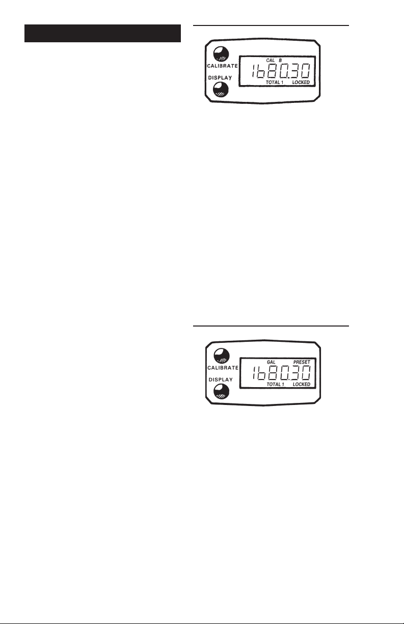
Figure 2
To change between totals, press and release
DISPLAY.
NOTE: Generally, readout displays change
when buttons are released.
Factory and Field
Calibration Curves
All calibration information is visible to the
user as words in the upper part of the display,
above the numeric digits.
All units will be congured with a “factory”
calibration curve, for which units of gallons
or litres may be selected by the user (“GAL”
or “LTR” will be visible). This curve is NOT
user adjustable: the word “PRESET” is
displayed to show this. (See Figure 3) The
factory calibration is stored permanently in
the computer’s memory.
Figure 3
Batch and Cumulative Totals
Total ags are displayed on the bottom line. A
Batch Total indicates ow during a single use.
It is labeled with TOTAL 2. To zero a batch
total, make sure it is displayed and hold down
DISPLAY for three seconds until the display
changes to zeros.
The Cumulative Total is the total of all liquid
measured since the meter’s power was con-
nected. At your rst use, the Cumulative Total
is not zero because of calibration at the factory.
The Cumulative Total is labeled as TOTAL
LOCKED indicating it cannot be manually
zeroed. (See Figure 2) The Cumulative Total
is zeroed only when batteries are removed or
go dead or when the Cumulative Total reaches
the maximum value of 999,999.
4
The “eld” calibration curve(s) may be set by
the user, and can be changed or modied at any
time using the calibration procedure described
below in the CALIBRATION section. Totals
or owrate derived from the eld calibration
are visible when the eld calibration setting
is selected “CAL B”.
Page 7
Selecting a Different
Calibration Setting
You can switch between GAL and LTR modes
at will without “corrupting” totalizer contents.
For example, the computer can totalize 10.00
gallons. If the user switches to LTR mode, the
display will immediately change to “37.85”
(the same amount in units of litres). GAL/LTR
switching also works in FLOWRATE mode.
To select a different calibration setting, rst
press and hold the CALIBRATE button.
Continue to hold it while also briey pressing
and releasing the DISPLAY button (you may
then also release the CALIBRATE button).
The ag indicators in the upper area of the
display will change to show the newly selected
calibration setting. Calibration settings change
in this order: GAL, LTR, CAL B, GAL (etc.).
While uid is owing only the GAL and LTR
selections may be made, however, when NO
uid ow is occurring, any setting may be
selected.
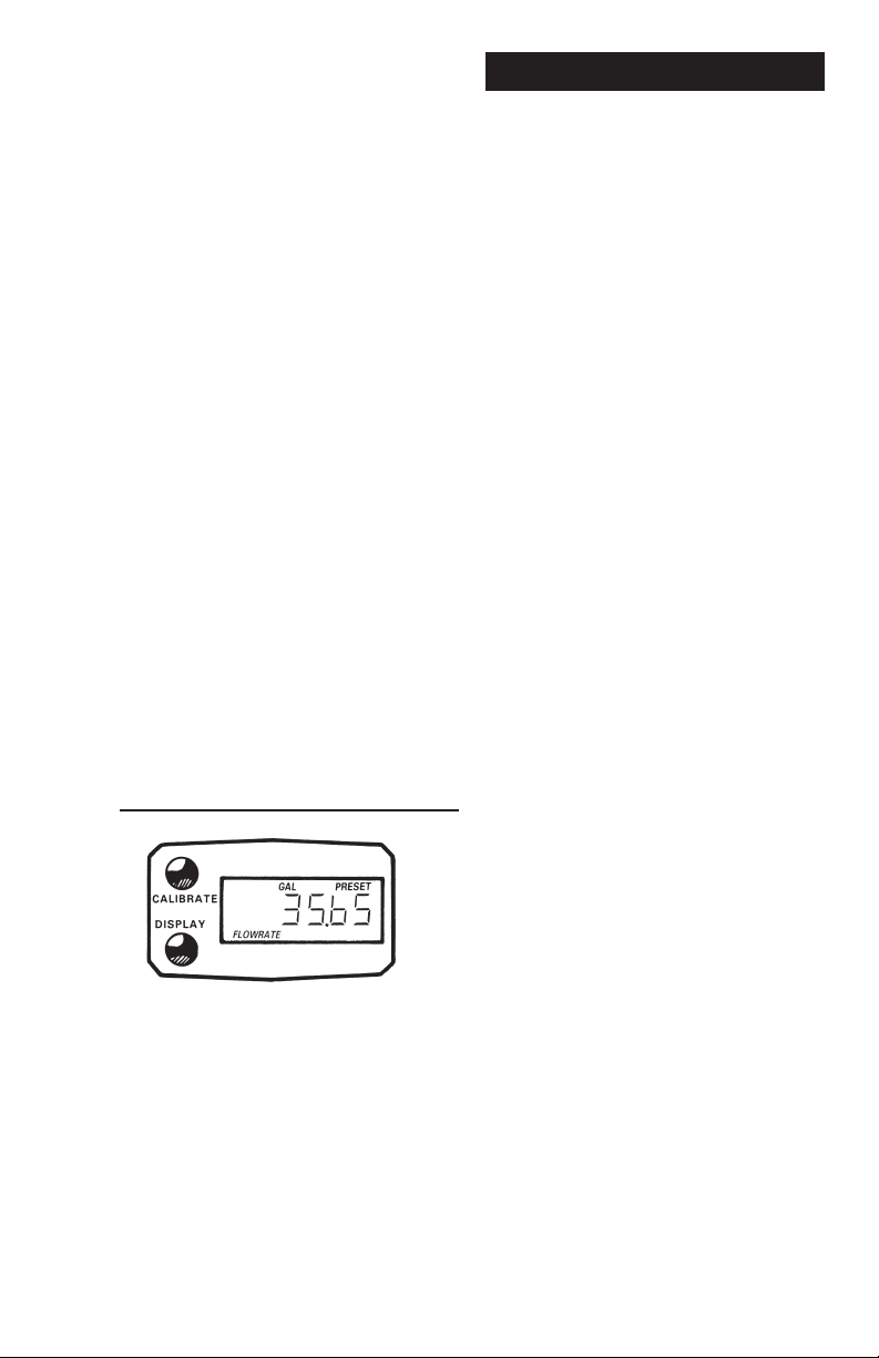
Flowrate
When this feature is activated, the word
FLOWRATE displays to the left on the bot-
tom line. (See Figure 4) When this ag is displayed, the numbers on the middle line reect
the rate of ow. To activate this feature, press
and release DISPLAY until FLOWRATE appears to the left on the bottom line.
Figure 4
Propeller
A small propeller displays to indicate liquid
is owing through the meter.
CALIBRATION
Factory Calibration settings are programmed
into each owmeter during production, and are
correct for light uids such as water, gasoline,
or diesel fuel. Factory Calibration is completed
with stoddard test solvent solvent (on 1" and
smaller owmeters) or water (on 1-1/2" and
larger owmeters) at 70°F (21°C). Readings
using the standard factory calibration curves
may not be accurate in some situations – for
example, if the unit measures a “heavy” uid
such as motor oil, especially under extreme
temperature conditions.
For improved accuracy under such conditions,
the ow computer allows for “eld” calibration, that is, user entry of custom calibration
parameters. A “single point” calibration may
yield acceptable accuracy with light liquids,
however, heavy liquids may require ve or
more calibration points to achieve a high
level of accuracy. Up to 15 custom calibration
points can be entered.
NOTE: A Field Calibration below the mini-
mum flo wrat e can adve rsely eff ect
accuracy.
The use of a uniformly dependable, accurate
calibration container is highly recommended
for the most accurate results. Due to high
flowrate, it is strongly recommended that
Field Calibration of 1-1/2" and 2" meters be
completed with a combination of volume and
weight using ne resolution scales.
For the most accurate results, dispense at a
owrate which best simulates your actual
operating conditions. Avoid “dribbling” more
uid or repeatedly starting and stopping the
ow – these actions will result in less accurate
calibrations.
Make sure you meet the meter’s minimum
owrate requirements.
1/2 inch meters - 1 GPM (3.8 LPM)
3/4 inch meters - 2 GPM (7.6 LPM)
1 inch meters - 5 GPM (19 LPM)
1-1/2 inch meters - 10 GPM (38 LPM)
2 inch meters - 20 GPM (76 LPM)
For best results, the meter should be installed
and purged of air prior to Field Calibration.
5
Page 8
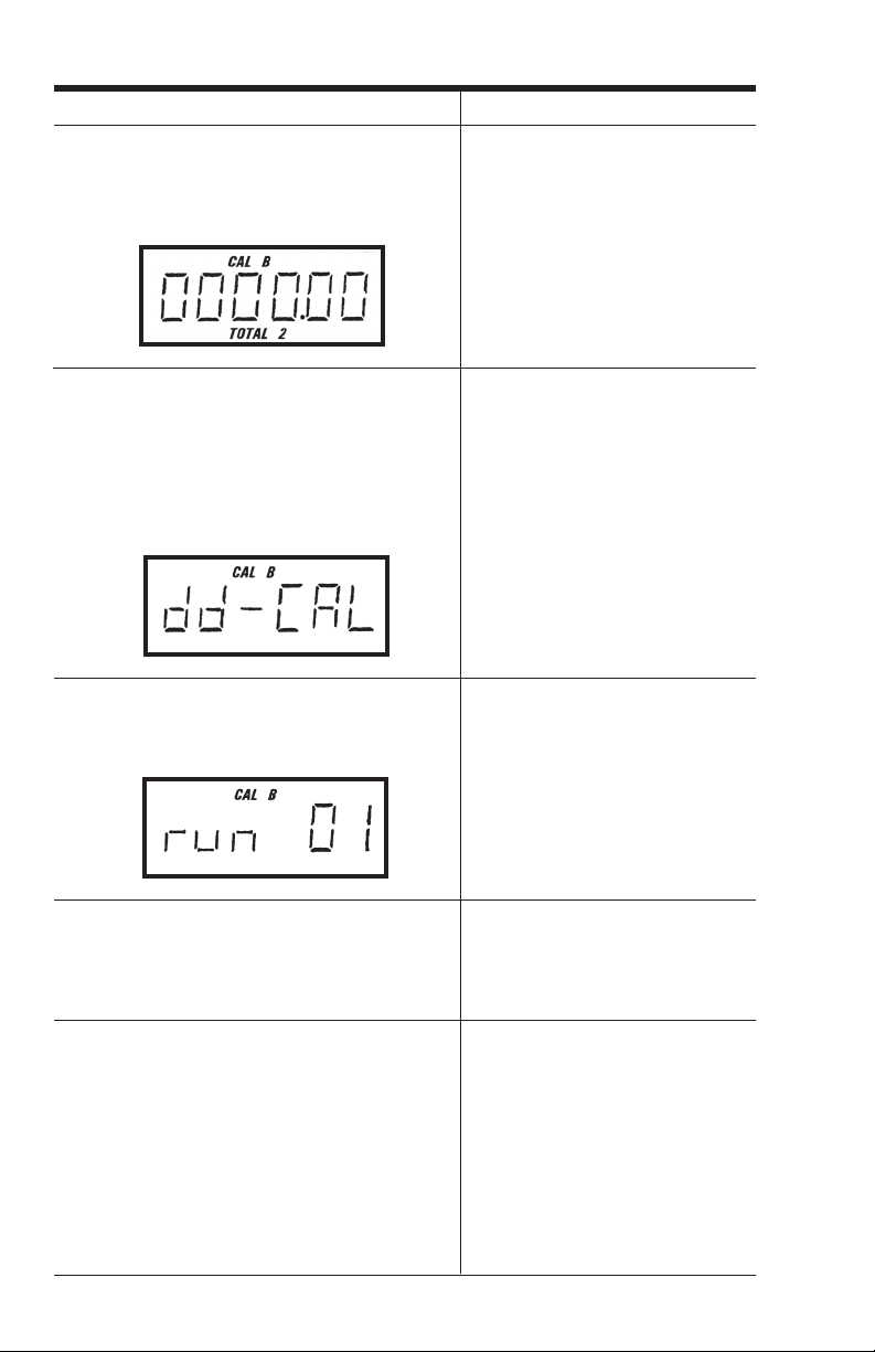
Dispense-Display Field Calibration Procedures
Your Actions Notes
1. Hold down CALIBRATE while pressing and Remember that Field Calibration
releasing DISPLAY until the Field Calibration curves are not preset.
curve appears (“CAL B” or “CAL C” message
will be displayed). Release both buttons.
2. To calibrate, press and hold the CALIBRATE This step puts the unit in dispense-
button. While continuing to hold CALIBRATE, display eld calibration mode
also press and hold the DISPLAY button. Hold (“dd-CAL”).
both buttons for about 3 seconds until you see
a blinking “dd-CAL” message. Once the
“dd-CAL” message appears, release both
buttons. You are now in eld calibration mode.
3. Once the buttons have been released from The computer is waiting for you to
Step 2, the display will show the blinking make a decision to either exit from
message “run 01.” eld calibration mode or to begin
a dispense run. If you want to exit
the calibration now, go to Step 11.
4. If you want to continue with the calibration,
but have not dispensed any uid yet, make
your nal preparations to your pumping
system, but don’t start pumping yet.
5. Start your pumping system so that uid ows When the computer displays a non-
through the meter. The display will stop blinking “run 01” message, it is
blinking and show the “run 01” message. sensing uid ow. For the most
Dispense into a container that allows you to accurate results, dispense at a ow
judge the amount of uid pumped. When you rate which best simulates your
have pumped the desired amount (for example, actual operating conditions. Avoid
10 gallons), stop the uid ow quickly. “dribbling” more uid or repeat edly starting and stopping the ow -
these actions will result in less
accurate calibrations.
6
Page 9
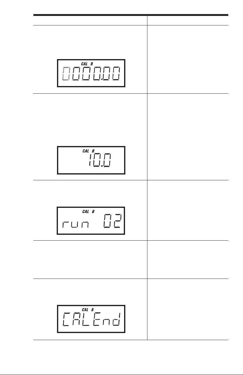
Your Actions Notes
6. Once the ow has stopped, briey press and When the display shows “0000.0”
release both buttons. At this point the computer the computer has stopped “watch-
display will change to “0000.0” with the left- ing” for uid ow and is now
hand digit blinking. waiting for you to enter some
numbers.
7. Enter the volume (amount) of uid that you
dispensed (for example, if your 10-gallon con-
tainer is full, enter “10.0” for gallons or “37.5”
for litres). To enter numbers use the CALI BRATE button to change the value of the
digit that is blinking and use the DISPLAY
button to shift the “blink” to the next digit.
8. Once the correct number has been entered, brief- You have installed the new cal ly press and release both buttons. The display curve point. You are ready to end
will now change to a blinking “run 02” message. calibration (Step 10) or enter
another new calibration point
(Step 9).
9. To enter another calibration point, go back It is possible to set up to 15 cal-curve
and repeat Steps 3 through 8. points, and the “run ##” message
will increment each time you repeat
the calibration process (run 01,
run 02, run 03, etc., up to run 15).
10. To end calibration, press and hold both After you release the buttons, the
buttons for about 3 seconds until you see the computer will resume normal
“CAL End” message. operations with the new cal point(s)
active.
7
Page 10
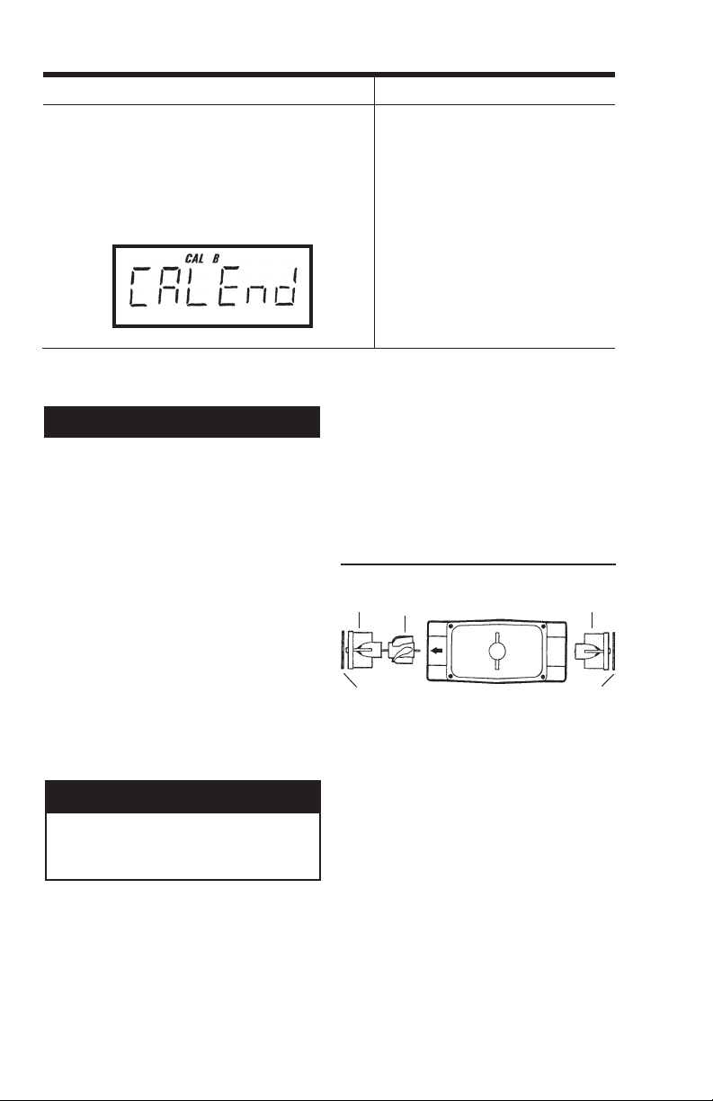
Dispense-Display Field Calibration Procedures - cont’d.
Your Actions Notes
11. If you HAVE NOT dispensed any uid, you After you release the buttons, the
can exit calibration without changing the cal computer will resume normal
curve. If the message “run 01” is showing operation and the old curve (if you
and you have not dispensed any uid, hold have entered one in the past) is
both buttons for about 3 seconds until you still intact.
see a “CAL End” message.
MAINTENANCE
Verify Accuracy
Before use, check the turbine’s accuracy and
verify calibration.
1. Make sure there is no air in the system.
2. Measure an exact known volume into an
accurate container.
3. Verify the volume against the readout or
recording equipment.
NOTE: If necessary, use a correction factor to
gure nal volume.
For best results, accuracy should be veried
periodically as part of a routine maintenance
schedule.
Remove the Turbine
! ! ! WARNING ! ! !
!
▲
▲
During turbine removal, liquid may spill.
Follow the liquid manufacturer’s safety
precautions for clean up of minor spills.
1. Ensure all liquid is drained from the tur-
bine. Wear protective clothing as necessary.
2. Loosen both ends of the turbine. Use a
wrench only on the turbine’s wrench ats.
3. If the turbine is not immediately installed
again, cap lines as necessary.
Replace Internal Parts
1. Remove the turbine from the system as
detailed above.
NOTE: Carefully notice the orientation of all
internal parts as they are removed, especially the orientation of the rotor to the
ow direction arrow. (See Figure 5)
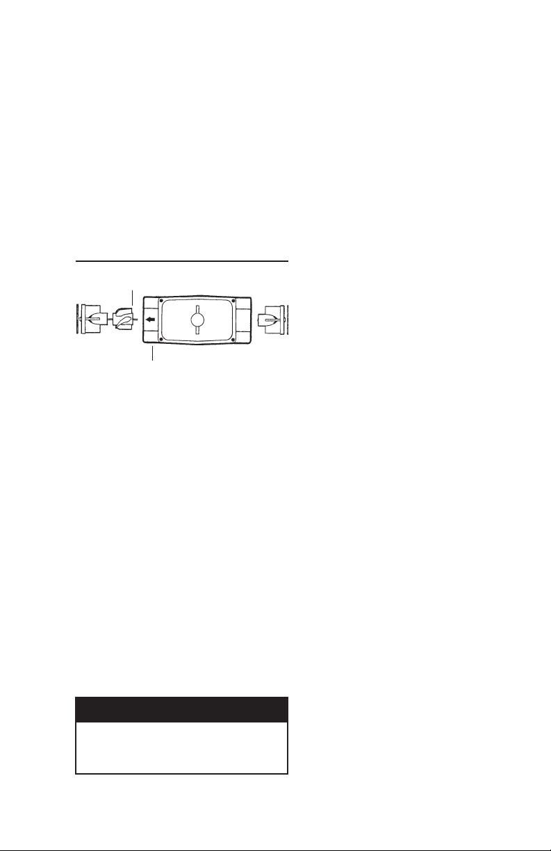
Figure 5
Support
2. Carefully clean residue off all parts. Re-
3. Using a small tool such as a screw driver
4. Carefully remove the rotor.
Rotor
Retaining Ring
move internal parts as detailed above. Note
orientation carefully for correct assembly.
Internal parts can be soaked for 10-15
minutes in compatible cleaning solutions.
Use a soft brush or small probe to carefully
remove residue from the rotor.
or awl, gently pry one retaining ring from
its groove. Remove the support. If necessary, use needle nose pliers. Little or no
force should be required.
Support
Retaining Ring
8
Page 11
CAUTION: Han dle the rotor carefully.
Even small scratches or nicks can affect
accuracy.
5. Turn the turbine over and remove the other
retaining ring. Remove the other support.
6. Clean, as detailed below, or discard as
necessary.
7. Replace one support and retaining ring.
Parts should drop easily into place with
little or no force.
8. Install the rotor. Make sure the wide end
of the rotor’s blades faces the ow direction. (See Figure 6)
Figure 6
Wide End of Rotor Blade
Flow Direction Arrow
9. Turn the turbine over and drop the second
support into place. Put the nal retaining
ring into position.
10. Reinstall the turbine, purge the system of
air, and verify accuracy before use.
Clean the Turbine
During use, the turbine should be kept full
of liquid to ensure that drying does not occur
inside the turbine. If drying or caking should
occur, the rotor will stick or drag, affecting
accuracy. To determine if the rotor is stuck or
dragging, gently blow air through the meter
and listen for the quiet whir of the rotor.
CAUTION: Never blow compressed air
through the meter. It could damage the
rotor.
1. Remove the turbine from the system fol
lowing the directions above.
-
2. When the rotor turns freely, assemble and
install it again following the instructions
above.
Display Electronics
The display electronics are powered by
lithium batteries which provide at least 4,000
hours of actual use. If the meter’s readout
should become dim or blank, the batteries
should be replaced. Replacement batteries
can be ordered from the factory. See details
in the Parts Section.
When batteries are disconnected or fail,
the Batch and Cumulative Totals return to
zero. Factory and Field Calibration Curves
are retained in the meter’s computer when
power is lost.
It is strongly recommended that battery check
and terminal cleaning be a part of a routine
maintenance schedule. Battery terminals
should be cleaned annually. Batteries can be
replaced without removing the meter from the
piping system.
Replacing the Batteries
1. Remove the corner screws from the meter
face and lift the display electronics from
the turbine.
2. Remove the batteries.
3. Check the battery terminals and remove
any corrosion.
4. Install the new batteries and make sure
the positive posts are positioned correctly.
When the batteries are installed correctly,
the computer powers on automatically
and the readout displays information.
5. Make sure the seal is fully seated before
placing the computer electronics on the
turbine. Tighten the four screws.
! ! ! WARNING ! ! !
!
▲
▲
Follow the liquid manufacturer’s instruc‑
tions for the disposal of contaminated
cleaning solvents.
9
Page 12

TROUBLESHOOTING
Symptom Probable Cause Corrective Action
Meter is not accurate 1. Field Calibration not perform- Field calibrate again or select Factory
ed properly Calibration.
2. Factory Calibration not suit- Perform a Field Calibration according to
able for liquid being measured Calibration Section.
3. Meter operated below mini- Increase owrate.
mum owrate
4. Meter partially clogged with Remove meter. Clean carefully. Make sure
dried liquid rotor spins freely.
5. Turbine bearings partially Remove meter. Clean carefully. Make sure
clogged with dried liquid rotor spins freely.
6. Sealant material wrapped Remove meter. Make sure rotor spins freely.
around rotor
7. Installed too close to ttings Install correctly.
8. Installed too close to motors Install correctly.
or electrically “noisy” envi ronment
9. Improper connections to Check all electrical connections. Reference
recording device appropriate installation instructions.
10. Accuracy needs verication Complete normal accuracy verication
procedures. Repeat periodically.
Readout faded or 1. Batteries weak, dead, or not Remove display electronics. Check and
blank connected replace batteries if necessary.
2. Display electronics defective Contact the factory.
Normal owrate 1. Field Calibration not perform- Field Calibrate again or select Factory
but meter does not ed correctly Calibration.
count (Meter comes
2. Rotor stuck or damaged Remove meter. Make sure rotor spins freely.
on when DISPLAY
button pushed)
3. Sealant material wrapped Remove meter. Make sure rotor spins freely.
around rotor
4. Display electronics defective Contact the factory.
Reduced owrate 1. Meter clogged with dried Remove meter. Clean carefully. Make sure
and meter does not liquids rotor spins freely.
count (Meter comes
on when DISPLAY 2. Below minimum owrate Increase ow.
button pushed)
Cannot get meter 1. Factory Calibration Hold down CALIBRATE and push and re-
into eld calibration (PRESET) curve active lease DISPLAY until PRESET ag goes off.
Proceed with calibration according to the
Calibration Section.
2. Display electronics circuit Replace display electronics. Contact the
board defective factory.
3. Button defective Replace display electronics. Contact the
factory.
Display electronics 1. Flowrate too low Try again and increase owrate to minimum
blinks “NO” after calibration rate. See Calibration Section.
eld calibration
2. Rotor not spinning freely Remove meter. Clean carefully. Make sure
rotor spins freely.
10
Page 13

SPECIFICATIONS - STAINLESS STEEL
All data on Models FTB791, FTB792, and FTB793 determined with 1 centipoise stoddard
solvent test uid at 70°F (21°C). Data on Models FTB794 and FTB795 is determined with
water at 70°F (21°C).
Models FTB791 FTB792 FTB793 FTB794 FTB795
Size 1/2 in. 3/4 in. 1 in. 1‑1/2 in. 2 in.
Linear Flow Range
Gallons/minute (GPM) 1-10 2-20 5-50 10-100 20-200
Liters/minute (LPM) 3.8-37.9 7.6-75.7 18.9-190 38-380 76-760
Extended Flow Range
Gallons/minute (GPM) 0.5-10 1-20 2.5-50 5-100 10-200
Liters/minute (LPM) 1.9-37.9 3.8-75.7 9.5-190 19-380 38-760
Maximum Flow
Gallons/minute (GPM) 15 30 75 150 300
Liters/minute (LPM) 56.8 113.6 284 568 1,136
Fluid Velocity
in Extended Range
Feet/second 0.5-10.6 0.6-12.1 0.93-18.6 0.8-15.9 0.96-19.1
Meters/second 0.2-3.2 0.2-3.7 0.28-5.7 0.24-4.8 0.29-5.8
Maximum Pressure Drop
in 10:1 Range
PSIG 8 7.5 5 4 4
bar 0.55 0.5 0.34 0.28 0.28
Frequency Range in
Linear Flow Range 45-450 Hz 37-370 Hz 45-475 Hz 35-350 Hz 33-330 Hz
Connections
NPT Female Inlet/Outlet Size 1/2 in. 3/4 in. 1 in. 1-1/2 in. 2 in.
Wrench Size:
Inch 1-1/16 in. 1-5/16 in. 1-5/8 in. 2-3/8 in. 3 in.
Millimeter 27mm 33mm 41mm 60mm 75mm
Weight*
Pounds 1.8 lbs. 2.0 lbs. 2.4 lbs. 4.0 lbs. 6.3 lbs.
Kilograms 0.8 kg 1.0 kg 1.1 kg 1.8 kg 2.9 kg
* Display electronics add 0.2 lbs. (0.1 kg) to total weight.
11
Page 14
SPECIFICATIONS - STAINLESS STEEL continued
Performance
Linear Range for 1/2 in. and 3/4 in.: 10:1 @ ±2.0% of reading
Linear Range for 1 in.: 10:1 @ ±1.5% of reading
Linear Range for 1-1/2 in. and 2 in: 10:1 @ ±1.0% of reading
Extended Range: 20:1 @ ±5.0% of reading
Repeatability: ±0.1%
Pressure Rating 1,500 PSIG (103 bar)
Wetted Components
Housing: 316 Stainless Steel
Journal Bearings: Ceramic (96% Alumina)
Shaft: Tungsten Carbide
Rotor and Supports: PVDF
Retaining Rings: 316 Stainless Steel
Temperature Range
Turbine only without computer: -40° to +250°F (-40° to +121°C)
Turbine with display electronics: +14° to +140°F (-10° to +60°C)
(Display electronics or accessory modules determine nal operational temperature.)
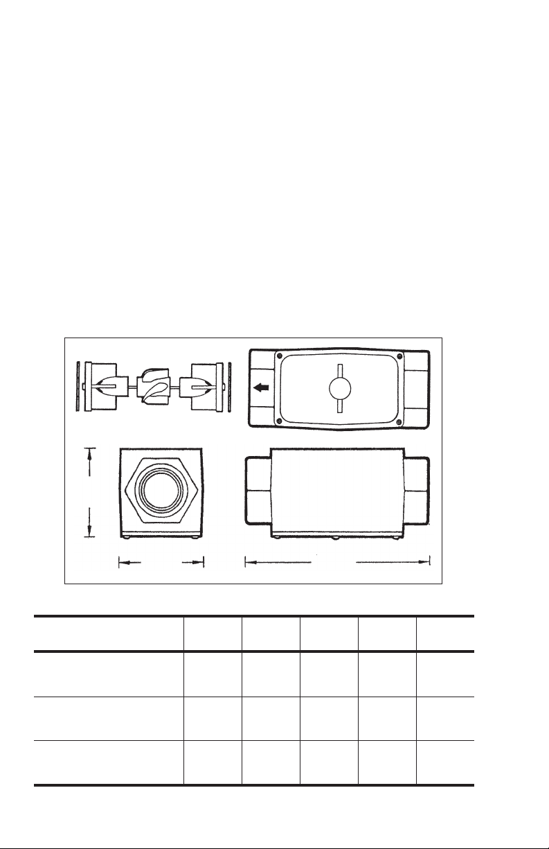
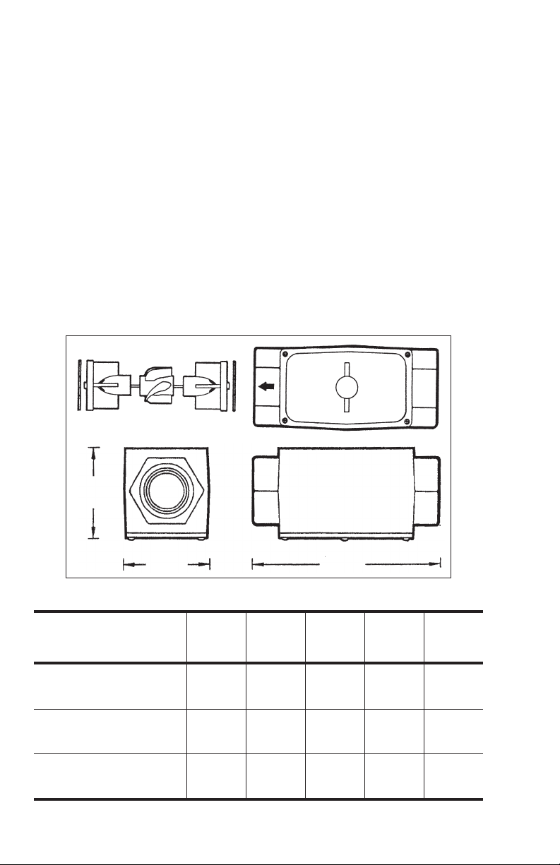
A
B
Dimensions
Models FTB791 FTB792 FTB793 FTB794 FTB795
Size 1/2 in. 3/4 in. 1 in. 1‑1/2 in. 2 in.
A = Height:
Inches 1.8 in. 2.0 in. 2.2 in. 2.8 in. 3.2 in.
Centimeters 4.6cm 5.1cm 5.6cm 7.1cm 8.2cm
B = Width
Inches 2.0 in. 2.0 in. 2.0 in. 2.7 in. 3.3 in.
Centimeters 5.1cm 5.1cm 5.1cm 6.9cm 8.4cm
C = Length
Inches 4.2 in. 4.3 in. 4.5 in. 5.3 in. 6.3 in.
Centimeters 10.7cm 10.9cm 11.4cm 13.5cm 16.0cm
Display electronics add 0.7 in. (1.8cm) to height of turbine.
12
C
Page 15

SPECIFICATIONS - BRASS
All data on FTB791-BRASS, FTB792-BRASS, and FTB793-BRASS determined with
1 centipoise stoddard solvent test uid at 70°F (21°C). Data on FTB794-BRASS and FTB795BRASS is determined with water at 70°F (21°C).
Models FTB791‑ FTB792‑ FTB793‑ FTB794‑ FTB795‑
BRASS BRASS BRASS BRASS BRASS
Size 1/2 in. 3/4 in. 1 in. 1‑1/2 in. 2 in.
Linear Flow Range
Gallons/minute (GPM) 1-10 2-20 5-50 10-100 20-200
Liters/minute (LPM) 3.8-37.9 7.6-75.7 18.9-190 38-380 76-760
Extended Flow Range
Gallons/minute (GPM) 0.5-10 1-20 2.5-50 5-100 10-200
Liters/minute (LPM) 1.9-37.9 3.8-75.7 9.5-190 19-380 38-760
Maximum Flow
Gallons/minute (GPM) 15 30 75 150 300
Liters/minute (LPM) 56.8 113.6 284 568 1,136
Fluid Velocity
in Extended Range
Feet/second 0.5-10.6 0.6-12.1 0.93-18.6 0.8-15.9 0.96-19.1
Meters/second 0.2-3.2 0.2-3.7 0.28-5.7 0.24-4.8 0.29-5.8
Maximum Pressure Drop
in 10:1 Range
PSIG 8 7.5 5 4 4
bar 0.55 0.5 0.34 0.28 0.28
Frequency Range in
Linear Flow Range 45-450 Hz 37-370 Hz 45-475 Hz 35-350 Hz 33-330 Hz
Connections
NPT Female Inlet/Outlet Size Yes Yes Yes Yes Yes
Female Yes Yes Yes Yes Yes
Inlet/Outlet Size 1/2 in. 3/4 in. 1 in. 1-1/2 in. 2 in.
Wrench Size:
Inch 1-1/16 in. 1-5/16 in. 1-5/8 in. 2-3/8 in. 3 in.
Millimeter 27mm 33mm 41mm 60mm 75mm
Weight*
Pounds 2.0 lbs. 2.3 lbs. 2.7 lbs. 6.0 lbs. 9.6 lbs.
Kilograms 0.9 kg 1.0 kg 1.2 kg 2.7 kg 4.3 kg
* Computer electronics add 0.2 lbs. (0.1 kg) to total weight.
13
Page 16
SPECIFICATIONS - BRASS continued
Performance
Linear Range for 1/2 in. and 3/4 in.: 10:1 @ ±2.0% of reading
Linear Range for 1 in.: 10:1 @ ±1.5% of reading
Linear Range for 1-1/2 in. and 2 in: 10:1 @ ±1.0% of reading
Extended Range: 20:1 @ ±5.0% of reading
Repeatability: ±0.1%
Pressure Rating 300 PSIG (21 bar)
Wetted Components
Housing: Brass
Journal Bearings: Ceramic (96% Alumina)
Shaft: Tungsten Carbide
Rotor and Supports: PVDF
Retaining Rings: 316 Stainless Steel
Temperature Range
Turbine only without computer: -40° to +250°F (-40° to +121°C)
Turbine with display electronics: +14° to +140°F (-10° to +60°C)
(Display electronics or accessory modules determine nal operational temperature.)
A
B
Dimensions
Models FTB791‑ FTB792‑ FTB793‑ FTB794‑ FTB795‑
BRASS BRASS BRASS BRASS BRASS
Size 1/2 in. 3/4 in. 1 in. 1‑1/2 in. 2 in.
A = Height:
Inches 1.8 in. 2.0 in. 2.2 in. 2.8 in. 3.2 in.
Centimeters 4.6cm 5.1cm 5.6cm 7.1cm 8.2cm
B = Width
Inches 2.0 in. 2.0 in. 2.0 in. 2.7 in. 3.3 in.
Centimeters 5.1cm 5.1cm 5.1cm 6.9cm 8.4cm
C = Length
Inches 4.2 in. 4.3 in. 4.5 in. 5.3 in. 6.3 in.
Centimeters 10.7cm 10.9cm 11.4cm 13.5cm 16.0cm
Computer electronics add 0.7 in. (1.8cm) to height of turbine.
14
C
Page 17
SPECIFICATIONS continued
Display Specifications
Input Pulse Rate:
Minimum Pulse In: DC
Minimum Coil Input: 10 Hz
Maximum Raw: 1,000 Hz
K‑Factor:
Minimum: 0.1 pulses/unit
Maximum: 999,999 pulses/
unit
Field Calibration:
Minimum Time: 10 seconds
Readout Totals:
Minimum Display: 0.01
Maximum Display: 999,999
Temperatures:
Operational: +14° to +140°F
(-10° to +60°C)
Storage: -40° to +158°F
(-40° to +70°C)
If wider operating temperature ranges
are desired, reference information on
Remote Kits.
Power:
Internal Power Supply: 2 Lithium
Batteries at
3 volts each
Minimum Battery Life: 4,000 opera-
tional hours
Optional External Power: 7-30 VDC ±5%
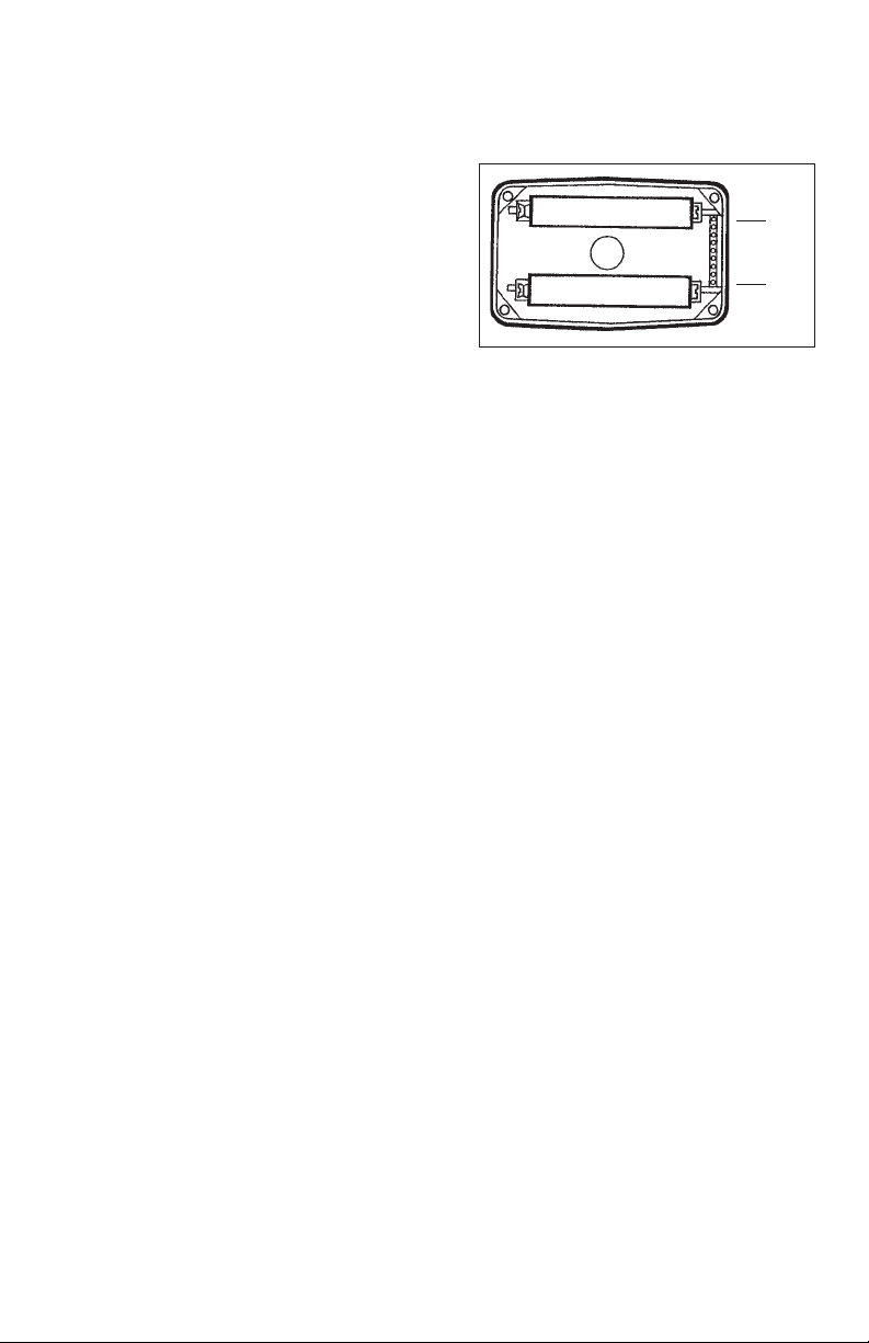
Display Electronics Terminal
Connections
J 1
J 10
J‑1 Reset
When connected by a jumper wire
to Ground (J1-6), this has the same
effect as initial power up and zeroes
out all totalizers.
J‑2 Pulse Signal Output
This supplies a high-level amplied
open collector signal. Output will
withstand a maximum open-circuit
voltage of 60 volts DC and a maxi-
mum closed-circuit of 100 mA.
J‑3 Not Used
J‑4 Pulse Signal Input
Requires a sine or square wave with
open-circuit voltage of 3-30 volts
P-P, a maximum rise/fall rate of
0.01 V/µ second and a maximum
frequency of 750 Hz.
J‑5 Power Input
When used with Ground (J1-6),
this has reverse polarity protection,
but no on-board voltage regulation.
Supplied voltage must be 5.75 volts
DC ±5%.
J‑6 Ground
J‑7, 8, Programming interfaces. Not access-
9, 10 able to user.
NOTE: Safety approvals are void if any
external connections are made to
computer electronics.
15
Page 18
SPECIFICATIONS continued
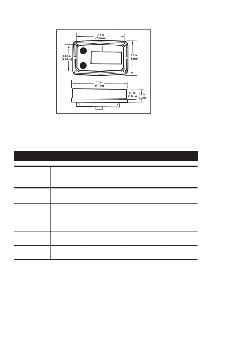
MODEL NUMBERS - STAINLESS STEEL
Extended
Model No. Model No.* Range Range FNPT
w/Display w/o Display GPM (LPM) Low Flow† Size
FTB791 FTB791-ND 1-10 0.5 1/2"
(3.8-37.9) (1.9)
FTB792 FTB792-ND 2-20 1 3/4"
(7.6-75.9) (3.8)
FTB793 FTB793-ND 5-50 2.5 1"
(19-190) (9.5)
FTB794 FTB794-ND 10-100 5 1-1/2"
(38-380) (9.0)
FTB795 FTB795-ND 20-200 10 2"
(76-760) (38)
* Requires signal output module P/N - FLSC790-P-ND ordered separately.
† Extended low ow range and eld calibration for viscosity available on - ND units w/o display.
16
Page 19

MODEL NUMBERS - BRASS
Extended
Model No. Model No.* Range Range FNPT
w/Display w/o Display GPM (LPM) Low Flow† Size
FTB791- FTB791-ND- 1-10 0.5 1/2"
BRASS BRASS (3.8-37.9) (1.9)
FTB792- FTB792-ND- 2-20 1 3/4"
BRASS BRASS (7.6-75.9) (3.8)
FTB793- FTB793-ND- 5-50 2.5 1"
BRASS BRASS (19-190) (9.5)
FTB794- FTB794-ND- 10-100 5 1-1/2"
BRASS BRASS (38-380) (9.0)
FTB795- FTB795-ND- 20-200 10 2"
BRASS BRASS (76-760) (38)
* Requires signal output module P/N - FLSC790-P-ND ordered separately.
† Extended low ow range and eld calibration for viscosity available on - ND units w/o display.
17
Page 20

PARTS & ACCESSORIES
Order Replacement Kits with the part numbers given here.
Part Number Description
FTB890-ORING O-Ring
FTB791-RK (1/2 inch) Rotor/Support Replacement Kit
FTB792-RK (3/4 inch) Rotor/Support Replacement Kit
FTB793-RK (1 inch) Rotor/Support Replacement Kit
FTB794-RK (1-1/2 inch) Rotor/Support Replacement Kit
FTB795-RK (2 inch) Rotor/Support Replacement Kit
FTB791-RETAINING (1/2 inch) Retaining Ring
FTB792-RETAINING (3/4 inch) Retaining Ring
FTB793-RETAINING (1 inch) Retaining Ring
FTB794-RETAINING (1-1/2 inch) Retaining Ring
FTB795-RETAINING (2 inch) Retaining Ring
Field Installable Options and Accessories
Model Number Description
FLSC790-MA 4-20 mAdc Output Module
FLSC790-P Pulse Output Module
FLSC790-P-DC External Power Module for FLSC790-P (9-30Vdc)
FTB790-RK Remote Display Kit Module
FTB790-RK-FM FM Approved Remote Display Kit Module
FLSC790-BATT Replacement Batteries
FLSC790-P-ND Pulse Output for Models without Displays (-ND sufx)
Except as noted, Options and Accessories are for Display Models only and only one Module may be installed per unit.
All models are supplied with 10 ft. cable. Cable may be cut or extended as required. Customer supplied pull-up resistor
required, 820 ohm (min).
(open collector output)
(open collector output)
18
Page 21

Page 22

Page 23

Page 24

M-3162/0308
 Loading...