

Page 1
TM
NORWALK, CT
User’s Guide
Shop online at
omega.com
e-mail: [email protected]
For latest product manuals:
www.omegamanual.info
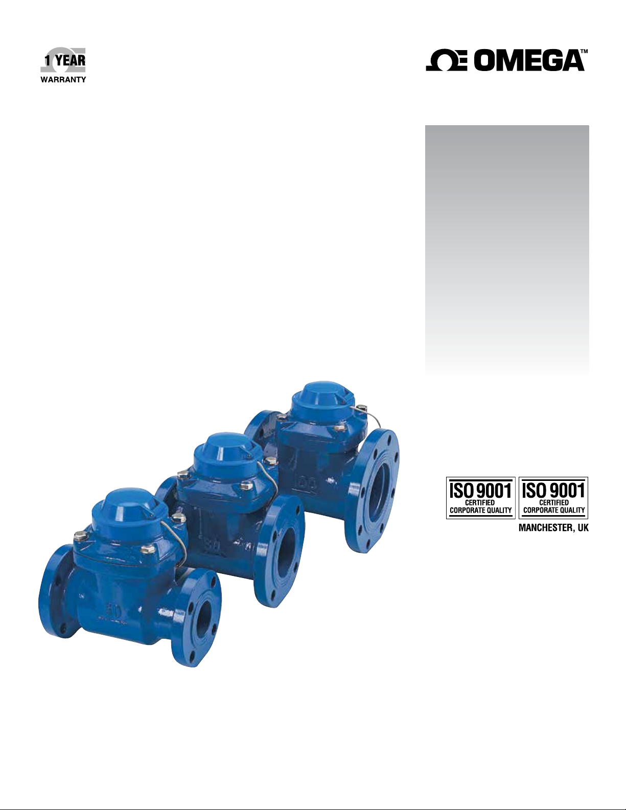
FTB-630 Series
Turbine Meter with
Available Pulse Output
Page 2

omega.com [email protected]
Servicing North America:
U.S.A. Omega Engineering, Inc.
Headquarters: Toll-Free: 1-800-826-6342 (USA & Canada only)
Customer Service: 1-800-622-2378 (USA & Canada only)
Engineering Service: 1-800-872-9436 (USA & Canada only)
Tel: (203) 359-1660 Fax: (203) 359-7700
e-mail: [email protected]
For Other Locations Visit omega.com/worldwide
The information contained in this document is believed to be correct, but OMEGA accepts no liability for any errors it contains, and reserves
the right to alter specifications without notice.
Page 3
GENERAL INFORMATION and SPECIFICATIONS
GENERAL INFORMATION
FTB-630 Series turbine meters are dry-register mechanical
totalizers that offer accurate, economical reading of high
flows with low pressure loss. The horizontal-axis turbine
drives a vertical shaft, which is magnetically coupled to the
sealed register.
In addition to mechanical totalizing, registers can be
equipped with magnetic pulse reed sensors well suited for
remote total-izing, pacing of electronic metering pumps,
and water treat-ment applications.
FEATURES
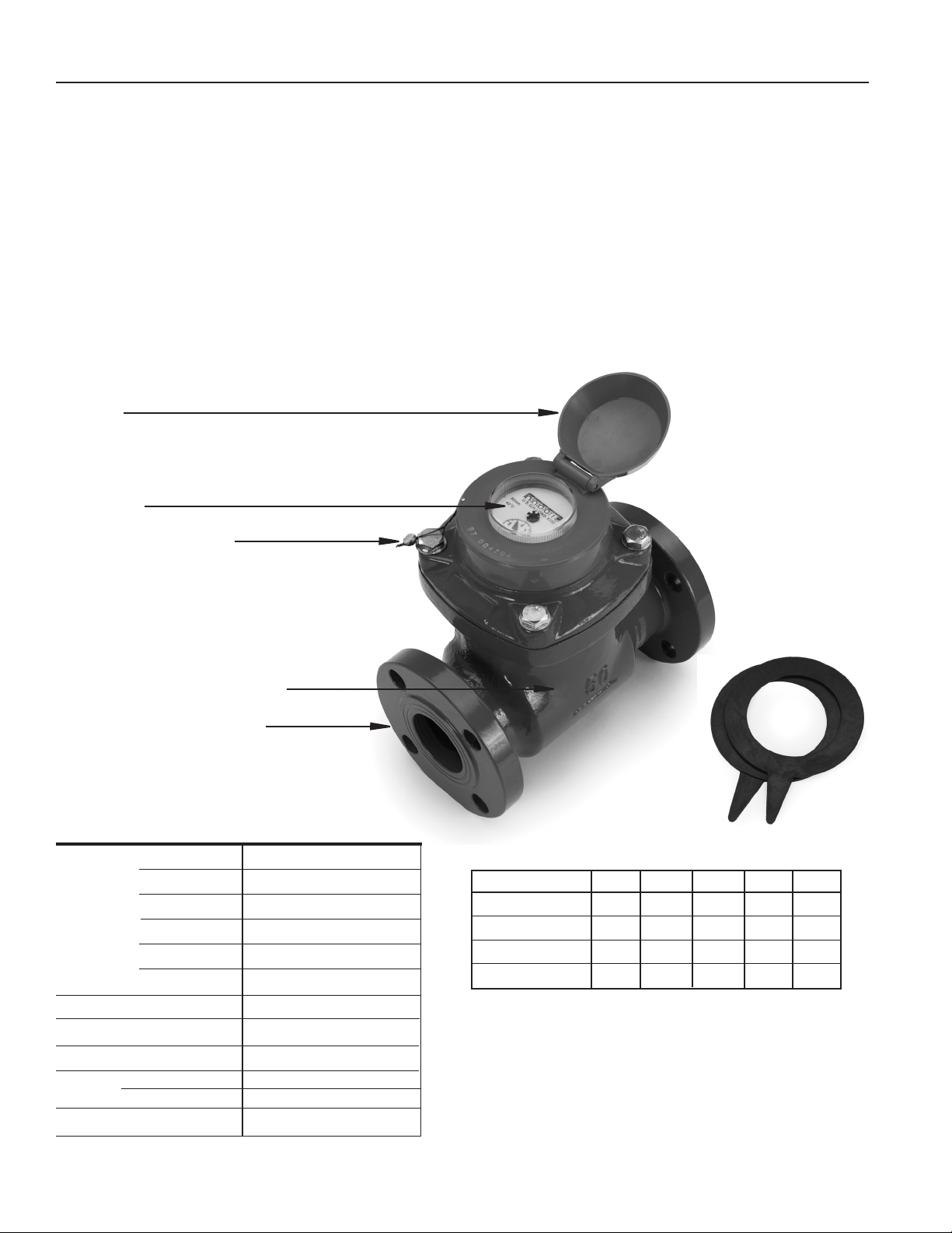
Lid
Display
Security bolt and seal
Bodies are manufactured of tough cast iron and
epoxy coated for protection. Tungsten steel shafts and jewel
bearings further enhance the durability of these meters.
Simple removal of the top flange brings out all parts for
inspection, repair, or replace-ment. The meter has a tamper-
evident seal to call attention to unauthorized access.
Epoxy-coated cast iron body
150 lb. ANSI drilling ange
SPECIFICATIONS
Materials Meter Body
Register Plate
Drive Magnet
Turbine
Turbine Shafts
Bearings
Flanges
Maximum Pressure
Maximum Temperature
Accuracy* Above Transition
Below Transition
Reed Switch
*Specications subject to change
Cast iron, epoxy coating
ABS plastic
Alnico
Plastic
Tungsten steel
Jewel
150 lb. ANSI drilling
200 psi (14 bar)
105˚ F (40˚ C)
+/-2% of reading
+/-5% of reading
100 mA @ 24 Vac/dc
2” Meter
Gaskets
included
FLOW RANGE (GPM)
2" 3" 4" 6” 8”
Minimum
Max. Continuous
Max. Intermittent
Transition*
*The ow rate at which accuracy changes from +/-2% of reading (above
Transition) to +/-5% of reading (below Transition).
2 5.3 8 20 33
132 352 528 1320 2200
165 440 660 1650 2750
16 24 40 80 140
Page 2
Page 4
INSTALLATION
The following installation recommendations are adapted
from the American Water Works Manual M6, and will result
in the best meter life and accuracy.
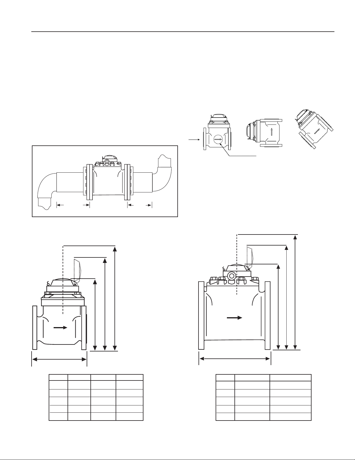
Piping Conditions. It is recommended that the meter be
installed with at least ten diameters of straight pipe
upstream and five diameters downstream from elbows,
tees, crosses, valves, and other fittings. If less straight pipe
is available, or if debris are likely to go through the meter,
installation of a stan-dard plate-type strainer directly
upstream is recommended. If a basket-type strainer is
used, it should be located at least five diameters upstream.
Avoid conditions of trapped air or partially-filled pipe. This
can occur when there is low flow and open discharge near
to the meter.
10X Dia. 5X Dia.
Flanges. The FTB-630 Series meter is compatible with any
standard 150 lb. ANSI drilling, flat or raised face. Take care
that gaskets (included) do not protrude into the meter due
to misalignment. Adhering the gasket to the meter flange
with gasket adhesive is a good practice that will aid
installation.
Position. FTB-630 Series are all-position meters, and can
be installed horizontally or vertically. Horizontal with
register facing up is recommended when possible.
Flow
Flow Arrow
DIMENSIONS
L
L
H
H1
H2
Wt.
H1 = Lid clearance for reading display
H2 = Head clearance for replacing turbine insert
H H1 H2
2", 3", 4"
2" 3" 4"
9.625" 8.86" 9.84"
10.08" 10.87" 11.26"
12.91" 13.70" 14.09"
15.75" 15.75" 15.75"
31 lbs. 45 lbs. 47 lbs.
H H1 H2
L
6" 8"
L
H
H1
H2
Wt.
H1 = Lid clearance for reading display
H2 = Head clearance for replacing turbine insert
11.81" 13.78"
13.60" 14.78"
16.44" 17.62"
19.68” 19.68”
95 lbs. 131 lbs.
6", 8"
Page 3
Page 5
MAINTENANCE AND REPAIR
CAUTION: Before breaking the tamper-
evident seal on your meter, be sure that
you are in compliance with any regulatory
requirements (if applicable).
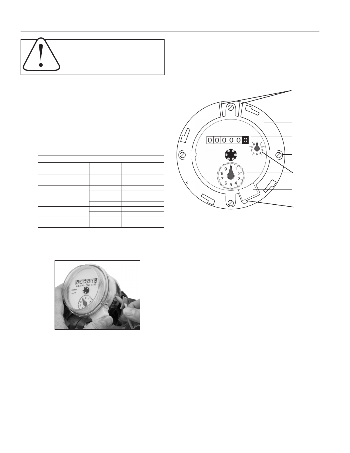
Register Removal. Clip and remove the copper security wire
from the ange bolt (see Caution note). Remove the security
pin that holds the lid in place, twist the lid and lift it off. Lift the
register free from the meter, noting orientation.
Field-Changing Pulse Rates. For the contacting head option,
FTB-630 Series meters use a meter-mounted reed switch to
provide a two-wire dry contact. To add a reed switch or change
your pulse rate in the eld, remove the register as described
above. Then:
1. Choose desired pulse rate and switch position.
Setting Your Pulse Rate
Size Size Pulse Reed Switch
(inches) (mm) Rate Position
2” 50
3” 80
4” 100
6” 150
8” 200
10 x1
100 x10
100 x10
1,000 x100
100 x10
1,000 x100
100 x10
1,000 x100
1,000 x100
10,000 x1000
2. Insert the gray reed switch sensor into the side of
the register nearest the dial with desired pulse rate.
4. Replace the register with the solid plastic tab seated
in the retaining ring to prevent rotation.
5. Thread the reed switch cable through the channel
in the retaining ring to the outside of the meter.
6. Reverse the procedure to close up the meter.
Recalibration. For meters used for revenue-billing purposes,
some states require periodic calibration checking. This type
of turbine meter is most commonly checked every four years.
Testing may be done by a local mobile meter service or in a
private or municipal meter shop. Changes in calibration should
be made at an authorized meter shop.
Cable channel
2” meter
Retaining ring
Totalizer
U.S.GALLONS X100
50mm
40˚C
X10
X1
Retaining ring
screws (4)
Pulse rate dials
Plastic tab
(on register)
Alignment notch
Turbine Insert Replacement. The entire turbine insert comes
out as a unit without removing the meter from the pipe. Carefully
noting position and retaining parts for reassembly...
1. Remove the lid and register as described.
2. After relieving pressure inside the meter, remove
the four ange hex-screws and washers.
3. Lift the ange and insert out in one piece, rocking
gently to break the seal.
4. Remove the four retaining ring screws, and lift
the retaining ring and ange off the turbine insert.
5. Remove and replace the large O-ring around the
top opening of the meter body.
6. Reassemble the retaining ring and ange on top of
the new insert. Be sure the alignment notch in the
retaining ring is directly above the screw in the
insert’s top plate.
7. Replace the entire mechanism in the meter body
with the drilled screw head in the same corner as
the security pin.
8. Replace the lid with a twist of the wrist, insert
the security pin in the tiny hole in the retaining ring,
and thread the security wire through the screw
head and the security pin. Afx lead seal and crimp.
Page 4
Page 6

NOTES
Page 7

WARRANTY/DISCLAIMER
OMEGA ENGINEERING, INC. warrants this unit to be free of defects in materials and workmanship for a
period of 13 months from date of purchase. OMEGA’s WARRANTY adds an additional one (1) month grace
period to the normal one (1) year product warranty to cover handling and shipping time. This ensures
that OMEGA’s customers receive maximum coverage on each product.
If the unit malfunctions, it must be returned to the factory for evaluation. OMEGA’s Customer Service
Department will issue an Authorized Return (AR) number immediately upon phone or written request.
Upon examination by OMEGA, if the unit is found to be defective, it will be repaired or replaced at no
charge. OMEGA’s WARRANTY does not apply to defects resulting from any action of the purchaser,
including but not limited to mishandling, improper interfacing, operation outside of design limits,
improper repair, or unauthorized modification. This WARRANTY is VOID if the unit shows evidence of
having been tampered with or shows evidence of having been damaged as a result of excessive corrosion;
or current, heat, moisture or vibration; improper specification; misapplication; misuse or other operating
conditions outside of OMEGA’s control. Components in which wear is not warranted, include but are not
limited to contact points, fuses, and triacs.
OMEGA is pleased to offer suggestions on the use of its various products. However,
OMEGA neither assumes responsibility for any omissions or errors nor assumes liability for
any damages that result from the use of its products in accordance with information provided
by OMEGA, either verbal or written. OMEGA warrants only that the parts manufactured by the
company will be as specified and free of defects. OMEGA MAKES NO OTHER WARRANTIES OR
REPRESENTATIONS OF ANY KIND WHATSOEVER, EXPRESSED OR IMPLIED, EXCEPT THAT OF
TITLE, AND ALL IMPLIED WARRANTIES INCLUDING ANY WARRANTY OF MERCHANTABILITY
AND FITNESS FOR A PARTICULAR PURPOSE ARE HEREBY DISCLAIMED. LIMITATION OF
LIABILITY: The remedies of purchaser set forth herein are exclusive, and the total liability of
OMEGA with respect to this order, whether based on contract, warranty, negligence,
indemnification, strict liability or otherwise, shall not exceed the purchase price of the
component upon which liability is based. In no event shall OMEGA be liable for
consequential, incidental or special damages.
CONDITIONS: Equipment sold by OMEGA is not intended to be used, nor shall it be used: (1) as a “Basic
Component” under 10 CFR 21 (NRC), used in or with any nuclear installation or activity; or (2) in medical
applications or used on humans. Should any Product(s) be used in or with any nuclear installation or
activity, medical application, used on humans, or misused in any way, OMEGA assumes no responsibility
as set forth in our basic WARRANTY/DISCLAIMER language, and, additionally, purchaser will indemnify
OMEGA and hold OMEGA harmless from any liability or damage whatsoever arising out of the use of the
Product(s) in such a manner.
RETURN REQUESTS/INQUIRIES
Direct all warranty and repair requests/inquiries to the OMEGA Customer Service Department. BEFORE
RETURNING ANY PRODUCT(S) TO OMEGA, PURCHASER MUST OBTAIN AN AUTHORIZED RETURN (AR)
NUMBER FROM OMEGA’S CUSTOMER SERVICE DEPARTMENT (IN ORDER TO AVOID PROCESSING
DELAYS). The assigned AR number should then be marked on the outside of the return package and on any
correspondence.
The purchaser is responsible for shipping charges, freight, insurance and proper packaging to prevent
breakage in transit.
FOR WARRANTY RETURNS, please have the
following information available BEFORE contacting
OMEGA:
1. Purchase Order number under which the product
was PURCHASED,
2. Model and serial number of the product under
warranty, and
3. Repair instructions and/or specific problems
relative to the product.
OMEGA’s policy is to make running changes, not model changes, whenever an improvement is possible. This affords our
customers the latest in technology and engineering.
OMEGA is a trademark of OMEGA ENGINEERING, INC.
© Copyright 2018 OMEGA ENGINEERING, INC. All rights reserved. This document may not be copied, photocopied,
reproduced, translated, or reduced to any electronic medium or machine-readable form, in whole or in part, without the prior
written consent of OMEGA ENGINEERING, INC.
FOR NON-WARRANTY REPAIRS, consult
OMEGA for current repair charges. Have
the following information available BEFORE
contacting OMEGA:
1. Purchase Order number to cover the COST
of the repair,
2. Model and serial number of the product, and
3. Repair instructions and/or specific problems
relative to the product.
Page 8

Where Do I Find Everything I Need for
Process Measurement and Control?
OMEGA…Of Course!
Shop online at omega.com
TEMPERATURE
MU
Thermocouple, RTD & Thermistor Probes, Connectors,
Panels & Assemblies
MU
Wire: Thermocouple, RTD & Thermistor
MU
Calibrators & Ice Point References
MU
Recorders, Controllers & Process Monitors
MU
Infrared Pyrometers
PRESSURE, STRAIN AND FORCE
MU
Transducers & Strain Gages
MU
Load Cells & Pressure Gages
MU
Displacement Transducers
MU
Instrumentation & Accessories
FLOW/LEVEL
MU
Rotameters, Gas Mass Flowmeters & Flow Computers
MU
Air Velocity Indicators
MU
Turbine/Paddlewheel Systems
MU
Totalizers & Batch Controllers
pH/CONDUCTIVITY
MU
pH Electrodes, Testers & Accessories
MU
Benchtop/Laboratory Meters
MU
Controllers, Calibrators, Simulators & Pumps
MU
Industrial pH & Conductivity Equipment
DATA ACQUISITION
MU
Communications-Based Acquisition Systems
MU
Data Logging Systems
MU
Wireless Sensors, Transmitters, & Receivers
MU
Signal Conditioners
MU
Data Acquisition Software
HEATERS
MU
Heating Cable
MU
Cartridge & Strip Heaters
MU
Immersion & Band Heaters
MU
Flexible Heaters
MU
Laboratory Heaters
ENVIRONMENTAL
MONITORING AND CONTROL
MU
Metering & Control Instrumentation
MU
Refractometers
MU
Pumps & Tubing
MU
Air, Soil & Water Monitors
MU
Industrial Water & Wastewater Treatment
MU
pH, Conductivity & Dissolved Oxygen Instruments
M5190/0918
 Loading...