

Page 1

Page 2

omega.com [email protected]
Servicing North America:
U.S.A. Omega Engineering, Inc.
Headquarters: Toll-Free: 1-800-826-6342 (USA & Canada only)
Customer Service: 1-800-622-2378 (USA & Canada only)
Engineering Service: 1-800-872-9436 (USA & Canada only)
Tel: (203) 359-1660 Fax: (203) 359-7700
e-mail: [email protected]
For Other Locations Visit omega.com/worldwide
The information contained in this document is believed to be correct, but OMEGA accepts no liability for any errors it contains,
and reserves the right to alter specifications without notice.
Page 3

CONTENTS
1. Introduction.................................................................................... 1
1.1 Specification .......................................................................... 1
1.2 Model Number....................................................................... 2
2. Operation ....................................................................................... 2
2.1 Principle.................................................................................3
2.2 Precautions............................................................................. 4
3. Installation ..................................................................................... 5
3.1 General Piping ....................................................................... 5
3.2 Strainers/Filters......................................................................7
3.3 Flow Straighteners and Installation Kits................................7
4. Maintenance................................................................................... 8
4.1 General................................................................................... 8
4.2 Cleaning Procedures .............................................................. 8
4.2.1 Chemical Cleaning......................................................... 8
4.2.2 Steam Cleaning .............................................................. 8
4.3 Pickup Coil Testing .............................................................10
4.4 Trouble Shooting ................................................................. 11
Appendix A: Drawing
Typical Assembly Sanitary Flowmeter with Installation Kit........... 12
Page 4

1. Introduction
The following information is provided for the proper installation and
maintenance of your instrument.
1.1 Specifications
Linearity: 0.5% of reading over linear flow range
Repeatability: 0.1% of reading
Flow Range: 0.35 to 650 gpm
Temperature Range:
Signal Output:
Materials of Construction:
Bearings:
Surface Finish:
End Fitting:
-450 °F to +450 °F w/ Standard MAG coil
10 mVrms or greater into 10K ohm load at
minimum flow rate.
316/316L Dual Rated Stainless Steel
Rotor 17.4 PH SS
Retaining Ring 15.7 MO PH SS
Hard Carbon Composite
32 micro inch finish
Tri-Grip® Sanitary Type
-1-
Page 5

1.2 Model Number
Linear Flow
Range
Model No. Fittings
FTB-401A 11/2″ TRI
FTB-402A 11/2″ TRI
FTB-403A 11/2″ TRI
FTB-404A 11/2″ TRI
FTB-405A 11/2″ TRI
FTB-406A 11/2″ TRI
FTB-407A 11/2″ TRI
FTB-408A 11/2″ TRI
FTB-409A 2″ TRI
FTB-410A 3″ TRI
FTB-411A 4″ TRI
Water
LPM GPM
1.32 to
0.35 to
13.2
3.5
2.84 to
0.75 to
28.4
7.5
4.73 to
1.25 to
36
9.5
6.62 to
1.75 to
61
16
9.5 to
2.5 to
110
29
15 to
4 to 60 5.1
227
23 to
6 to 93 4.3
352
30 to
8 to 130 3.0
492
57 to
15 to
852
225
95 to
25 to
1514
400
151 to
40 to
2460
650
Note: Operating pressure is limited by the TRI fitting.
Max
Pressure
Drop
(psid)
3.0
5.0
5.2
3.0
5.0
3.3
4.0
4.0
Length
mm
(in)
90.4
(3.56)
90.4
(3.56)
90.4
(3.56)
90.4
(3.56)
82.5
(3.25)
90.4
(3.56)
116.5
(4.59)
116.5
(4.59)
154
(6.06)
254
(10)
254
(10)
Nominal
K-factor
Pulses/Gal
15,000 3 lbs
8,900 3 lbs
5,800 3 lbs
5,200 3 lbs
2,200 3 lbs
840 3 lbs
400 4 lbs
230 4 lbs
120 7 lbs
97 8 lbs
45 12 lbs
Weight
kg
(lb)
-2-
Page 6

2. Operation
2.1 Principle
The turbine flow sensor consists of a rotor assembly which is supported
on a shaft held in place by triple tube clusters and secured with locking
nuts within the flowmeter housing.
The rotor is free to spin on a self lubricated ceramic ball bearing. A
magnetic type pickup coil is attached on the exterior of the flowmeter
housing.
A low mass rotor design allows for rapid dynamic response. The
deflector cones eliminate downstream thrust on the rotor and allows for
dynamic positioning of the rotor between deflector cones.
The dynamic positioning of the low mass rotor provides wider
rangeability and longer bearing life than that of conventional turbine
flowmeters. Integral flow straightening tubes minimize the effects of
upstream flow turbulence.
As the liquid flows through the flowmeter the rotor spins at rate
proportional to the volumetric liquid flowrate.
Each rotor blade passing through the pickup coil generates an electrical
pulse. The frequency of the pulses is proportional to flowrate. The
summation of pulses represents total amount of liquid volume passed
through the meter.
The number of pulses generated per unit of volume is called the
calibration factor or K-Factor. This calibration factor is used to
calculate flowrate and total amount of flow.
Material Selection and Construction
The housing is made of 316 stainless steel. The rotor is made of 17.4
pH stainless steel. Bearings are composite hard carbon, FDA approved.
-3-
Page 7

Flowmeter Calibrations
The standard calibration provided with an Omega turbine flowmeter
consists of a 10-point water calibration that is traceable to NIST. Based
on this water calibration, we derive an average k-factor for water for
the flowmeter.
The uncertainty of this calibration is typically 0.1%.
The K-factor on turbine flowmeters used on liquid service is NOT
density dependent.
2.2 Precautions
Do not drop the meter. Dropping the meter may result in damage
to the meter housing and/or internals.
Do not operate the meter at flowrates greater than the maximum
flowrate marked on the meter. Operating at flowrates greater than
the maximum flowrate may over-spin the meter. Over-spinning
may result in damage to the meter.
CAUTION: Avoid over-spinning the meter. Over-spinning the meter may
result in damage to the meter internals and lead to meter
failure.
-4-
Page 8

3. Installation
CAUTION: Turbine meter has to be installed with pickup coil pointing
down (see Appendix A) to ensure proper cleanability.
Inspect all packages for any indications of damage which may have
occurred during shipment.
Verify that all meter parts or auxiliary components have arrived with
the shipment. Refer to the packing list/invoice for a detailed list of
items included in the shipment.
3.1 General Piping
It is required to install meter with a minimum straight run of pipe
approximately 10 pipe diameters ahead of the inlet and 5 pipe
diameters following the outlet to avoid any effect of fluid swirls.
The meter housing is marked by a flow direction arrow and the inlet is
marked ‘IN’ and the outlet is marked ‘OUT’. The meter must be
installed in the piping in the correct orientation to ensure the most
accurate operation.
Install meter with adequate distance and isolation from electric motors,
transformers, welding equipment and solenoids to avoid any
electromagnetic interference from ambient electrical field.
When it is expected that flow will be intermittent, the meter should not
be mounted at a low point in the piping system. Solids which settle or
congeal in the meter may affect meter performance.
-5-
Page 9
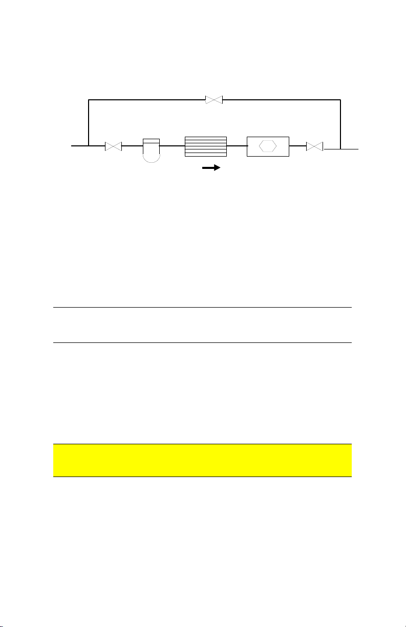
A typical flowmeter installation is shown below:
BYPASS RUN
Bypass Valve
Flow Straighener
Typical Flowmeter Installation
METER RUN
Turbine FlowmeterStrainer
Blocking ValveBlocking Valve
Blocking and Bypass valves should be installed if it is necessary to do
preventive maintenance on the flowmeter without shutting down the
flow system. The Bypass valve can be opened before the Blocking
valves are closed allowing the flow to continue while removing the
turbine flowmeter for service.
IMPORTANT
: All flow lines should be purged prior to installing the
meter. To prevent possible damage to the meter, install the
meter ONLY in flow lines that are clean and free of debris.
Upon initial start-up of the system a spool piece should be installed in
place of the flowmeter so that purging of the system can be performed
to remove all particle debris which could cause damage to the meter
internals. In applications where meter flushing is required after meter
service, care should be taken as to not over-spin the meter, as severe
meter damage may occur.
CAUTION: Avoid over-spinning the meter. Over-spinning the meter may
result in damage to the meter internals and lead to meter
failure.
-6-
Page 10

To maintain an accurate flow measurement it is necessary to maintain a
downstream pressure sufficient to prevent flashing/cavitation. Flashing
of the liquid will result in an indication of flow significantly higher
than the actual flow. In order to eliminate this condition adequate
downstream pressure must be maintained. The minimum required
downstream pressure may be calculated using the following equation:
Downstream pressure may be maintained by a downstream valve that
provides the necessary downstream pressure to prevent
flashing/cavitation in the metering run.
essurexVaporessureDropxessureMinimum Pr25.1Pr2Pr
3.2 Strainers/Filters
Turbine flowmeters are designed for use in a clean fluid service.
However, the service fluid may carry some particulate material which
would need to be removed before reaching the flowmeter. Under these
conditions a strainer/filter may be required to reduce the potential
hazard of fouling or damage that may be caused by foreign matter.
METER SIZE MESH SIZE PARTICLE SIZE
¼” to ½” 100 .0055
5
/8” to 1¼” 70 .008
1½” to 3” 40 .015
If a strainer/filter is required in the system, it should be located
upstream of the flowmeter taking care that the proper minimum
distance is kept between the strainer and flowmeter.
(Maximum)
3.3 Flow Straighteners and Installation Kits
Proper application of the Omega FTB-400A Series Flowmeter requires
a minimum inlet straight pipe run of 10 pipe diameters and a minimum
outlet straight pipe run of 5 pipe diameters.
Installation kits for the Omega FTB-400A Series Flowmeter consist of
two lengths of appropriate tubing cut to a length appropriate for the
upstream and downstream straight pipe run with appropriate end
fittings. Flow straightening sections may be provided within the
installation kit.
-7-
Page 11

4. Maintenance
4.1 Cleaning Procedures
The Omega FTB-400A Series flowmeters have been designed to allow
for cleaning by commercially accepted practices. These include
removing the flowmeter from the line for cleaning in an approved fluid,
flushing the line with an approved cleaning solution, and steam
cleaning. With all cleaning methods, care must be taken to not overspin the meter, as severe meter damage may occur.
CAUTION: Avoid over-spinning the meter. Over-spinning the meter may
result in damage to the meter internals and lead to meter
failure.
4.2.1 Chemical Cleaning
The flowmeters may be chemically cleaned using an approved
cleaning solution by removing the meter from the service line and
using a bath or by flushing the meter in place.
The hard carbon composite bearing designs used have been tested
and found to be compatible with the following CIP fluids
manufactured by Klenzade; Mandate, AC-300, AC-101, Principle,
and XY-12.
Following the cleaning operation, the cleaning solution should be
flushed from the meter and/or service line with potable water to
remove the chemically active cleaning solution.
Care should be taken to ensure that flowrates occurring during
chemical cleaning do not exceed the flow capacity of the
flowmeter.
4.2.2 Steam Cleaning
Steam cleaning is only recommended for meters with hard carbon
composite bearings.
The steam flow velocity during the cleaning should not exceed 1/3
of the maximum liquid flow capacity of the flowmeter.
-8-
Page 12

Steam Cleaning Rates at Various Steam Pressures
Meter
Size
1/4 1.25 1.70 2.25 2.50 1.72 1.05
3/8 2.70 3.67 4.75 5.39 3.68 2.25
1/2 3.50 4.73 6.14 7.00 4.74 2.90
5/8 5.78 7.82 10.20 11.50 5.02 4.80
3/4 10.50 14.20 18.40 20.90 6.32 8.70
1 21.70 29.40 38.10 43.10 7.35 18.00
1 ¼ 33.70 45.70 59.30 67.10 7.32 28.00
1 ½ 47.00 63.60 82.50 93.50 7.08 39.00
2 81.30 110.10 142.80 162.00 6.89 67.50
2 ½ 144.60 196.00 254.00 288.00 7.84 120.00
3 235.00 318.00 412.60 467.00 8.85 195.00
NOTES
1. PPH = Pounds Per Hour
2. The velocity is expressed for a line size equal to the inlet bore of the flowmeter.
3. The apparent GPM is provided since many applications have a flow rate indicator
50 psig
PPH1
which can be used to set a safe flow rate during the steam cleaning cycle.
75 psig
PPH1
100 psig
PPH1
125 psig
PPH1
Velocity
FPS2
Rate
GPM3
-9-
Page 13
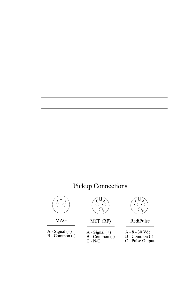
4.3 Pickup Coil Testing
Testing the MAG and MCP (RF) coils consists of measuring the
resistance with an ohmmeter. Resistance measurements are to be made
only when there is no flow through the meter.
1. Measure the resistance between pin A and pin B. The resistance
should be approximately as listed in the following table
common coils.
2. The resistance from any pin to the case should be greater than 1
Mohm.
COIL
DC RESISTANCE
(Ohms)
MC2PAHT
MCP3A
PC13-74G
PC13-74S
PC24-45G
PC24-45S
PC28-13G
PC28-14G
of some
15.0 10%
11.5 10%
1800 10%
1850 15%
1350 10%
1850 15%
120 20%
180 20%
If either resistance measurement fails, replace the pickup coil. Firmly
seat the new coil in the flowmeter and tighten the locking nut.
For specific coils not listed contact the HFC Customer Service Department for the
approximate resistance readings.
-10-
Page 14

4.4 Trouble Shooting
Refer to the following troubleshooting guide for assistance with
possible meter malfunctions:
TROUBLE CAUSE REMEDY
Fluid will not flow Meter clogged. Clean meter.
through the meter Line to meter
blocked.
Reduced flow through
the meter
Line to meter
Meter readings
inaccurate
Meter drag due to
Meter partially
clogged.
partially blocked.
Fluid flowrate is
not within meter
flow range.
improper
installation
Clean line to meter.
Clean meter.
Clean line to meter.
See “Specifications” for
min and max flowrates.
Replace internals.
-11-
Page 15
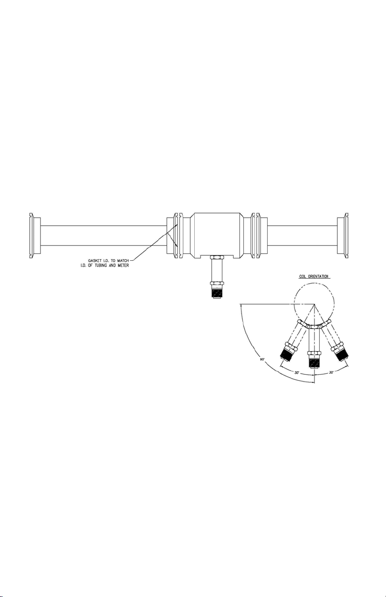
DRAWING
Typical Assembly
Sanitary Flowmeter with Installation Kit
-12-
Page 16

WARRANTY/DISCLAIMER
OMEGA ENGINEERING, INC. warrants this unit to be free of defects in materials and
workmanship for a period of 13 months from date of purchase. OMEGA’s WARRANTY adds
an additional one (1) month grace period to the normal one (1) year product warranty to
cover handling and shipping time. This ensures that OMEGA’s customers receive maximum
coverage on each product.
If the unit malfunctions, it must be returned to the factory for evaluation. OMEGA’s Customer
Service Department will issue an Authorized Return (AR) number immediately upon phone
or written request. Upon examination by OMEGA, if the unit is found to be defective, it
will be repaired or replaced at no charge. OMEGA’s WARRANTY does not apply to defects
resulting from any action of the purchaser, including but not limited to mishandling, improper
interfacing, operation outside of design limits, improper repair, or unauthorized modification.
This WARRANTY is VOID if the unit shows evidence of having been tampered with or shows
evidence of having been damaged as a result of excessive corrosion; or current, heat, moisture
or vibration; improper specification; misapplication; misuse or other operating conditions
outside of OMEGA’s control. Components in which wear is not warranted, include but are not
limited to contact points, fuses, and triacs.
OMEGA is pleased to offer suggestions on the use of its various products. However,
OMEGA neither assumes responsibility for any omissions or errors nor assumes
liability for any damages that result from the use of its products in accordance
with information provided by OMEGA, either verbal or written. OMEGA warrants
only that the parts manufactured by the company will be as specified and free of
defects. OMEGA MAKES NO OTHER WARRANTIES OR REPRESENTATIONS OF ANY
KIND WHATSOEVER, EXPRESSED OR IMPLIED, EXCEPT THAT OF TITLE, AND ALL
IMPLIED WARRANTIES INCLUDING ANY WARRANTY OF MERCHANTABILITY AND
FITNESS FOR A PARTICULAR PURPOSE ARE HEREBY DISCLAIMED. LIMITATION
OF LIABILITY: The remedies of purchaser set forth herein are exclusive, and the
total liability of OMEGA with respect to this order, whether based on contract,
warranty, negligence, indemnification, strict liability or otherwise, shall not exceed
the purchase price of the component upon which liability is based. In no event shall
OMEGA be liable for consequential, incidental or special damages.
CONDITIONS: Equipment sold by OMEGA is not intended to be used, nor shall it be used: (1)
as a “Basic Component” under 10 CFR 21 (NRC), used in or with any nuclear installation or
activity; or (2) in medical applications or used on humans. Should any Product(s) be used in or
with any nuclear installation or activity, medical application, used on humans, or misused in
any way, OMEGA assumes no responsibility as set forth in our basic WARRANTY / DISCLAIMER
language, and, additionally, purchaser will indemnify OMEGA and hold OMEGA harmless from
any liability or damage whatsoever arising out of the use of the Product(s) in such a manner.
Direct all warranty and repair requests/inquiries to the OMEGA Customer Service Department.
RETURN REQUESTS/INQUIRIES
BEFORE RETURNING ANY PRODUCT(S) TO OMEGA, PURCHASER MUST OBTAIN AN
AUTHORIZED RETURN (AR) NUMBER FROM OMEGA’S CUSTOMER SERVICE DEPARTMENT
(IN ORDER TO AVOID PROCESSING DELAYS). The assigned AR number should then be
marked on the outside of the return package and on any correspondence.
The purchaser is responsible for shipping charges, freight, insurance and proper packaging to
prevent breakage in transit.
FOR WARRANTY RETURNS, please have
the following information available BEFORE
contacting OMEGA:
1. Purchase Order number under which
the product was PURCHASED,
2. Model and serial number of the product
under warranty, and
3. Repair instructions and/or specific
problems relative to the product.
OMEGA’s policy is to make running changes, not model changes, whenever an improvement is possible.
This affords our customers the latest in technology and engineering.
OMEGA is a registered trademark of OMEGA ENGINEERING, INC.
© Copyright 2016 OMEGA ENGINEERING, INC. All rights reserved. This document may not be copied, photocopied,
reproduced, translated, or reduced to any electronic medium or machine-readable form, in whole or in part, without
the prior written consent of OMEGA ENGINEERING, INC.
FOR NON-WARRANTY REPAIRS,
consult
OMEGA for current repair charges. Have the
following information available BEFORE
contacting OMEGA:
1. Purchase Order number to cover the
COST of the repair,
2. Model and serial number of the product, and
3. Repair instructions and/or specific problems
relative to the product.
Page 17

Where Do I Find Everything I Need for
Process Measurement and Control?
OMEGA…Of Course!
Shop online at omega.com
TEMPERATURE
MU
Thermocouple, RTD & Thermistor Probes, Connectors, Panels & Assemblies
MU
Wire: Thermocouple, RTD & Thermistor
MU
Calibrators & Ice Point References
MU
Recorders, Controllers & Process Monitors
MU
Infrared Pyrometers
PRESSURE, STRAIN AND FORCE
MU
Transducers & Strain Gages
MU
Load Cells & Pressure Gages
MU
Displacement Transducers
MU
Instrumentation & Accessories
FLOW/LEVEL
MU
Rotameters, Gas Mass Flowmeters & Flow Computers
MU
Air Velocity Indicators
MU
Turbine/Paddlewheel Systems
MU
Totalizers & Batch Controllers
pH/CONDUCTIVITY
MU
pH Electrodes, Testers & Accessories
MU
Benchtop/Laboratory Meters
MU
Controllers, Calibrators, Simulators & Pumps
MU
Industrial pH & Conductivity Equipment
SM
DATA ACQUISITION
MU Communications-Based Acquisition Systems
MU Data Logging Systems
MU Wireless Sensors, Transmitters, & Receivers
MU Signal Conditioners
MU Data Acquisition Software
HEATERS
MU
Heating Cable
MU
Cartridge & Strip Heaters
MU
Immersion & Band Heaters
MU
Flexible Heaters
MU
Laboratory Heaters
ENVIRONMENTAL
MONITORING AND CONTROL
MU
Metering & Control Instrumentation
MU
Refractometers
MU
Pumps & Tubing
MU
Air, Soil & Water Monitors
MU
Industrial Water & Wastewater Treatment
MU
pH, Conductivity & Dissolved Oxygen Instruments
M2124/0618
 Loading...