

Page 1
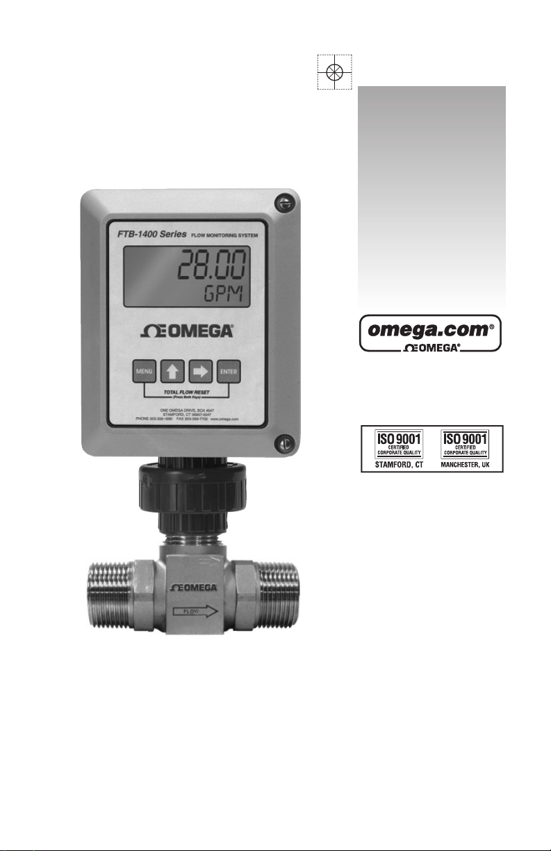
User’s Guide
Shop online at
omega.com
e-mail: [email protected]
For latest product manuals:
omegamanual.info
Series FTB-1400-MD
FTB-1400-RD
FTB-1400-SD
Flow Monitor - Simplified Version
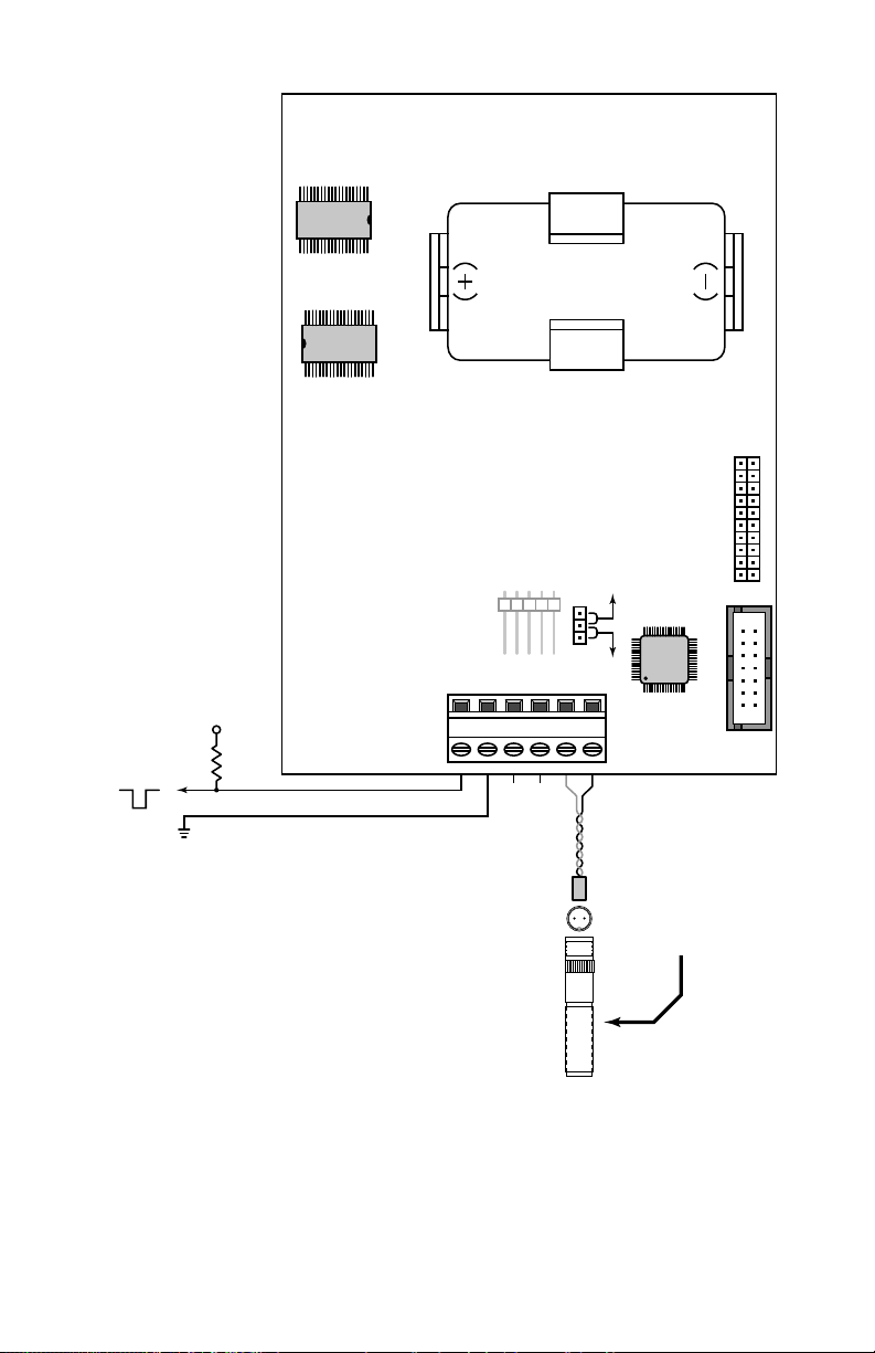
Page 2

OMEGAne t ®Online Service Internet e-mai l
o mega.com i [email protected]
Servicing North America:
U.S.A. : One Omega Drive, Box 4047
ISO 9001 Certied Stamford, CT 06907-0047
Canada :
Tel: (203) 359-1660
FAX: (203) 359-7700
e-mail: [email protected]
976 Bergar
Laval (Quebec) H7L 5A1, Canad a
Tel: (514) 856-6928
FAX: (514) 856-6886
e-mail: [email protected] a
For immediate technical or application assistance:
U.S.A. and Canada : Sales Service: 1-800-826-6342/1-800-TC-OMEGA
Customer Service: 1-800-622-2378/1-800-622-BEST
Engineering Service: 1-800-872-9436/1-800-USA-WHEN
®
®
®
Mexico : En Espa n ˜o l: (001) 203-359-7803
e-mail: [email protected]
FAX: (001) 203-359-7807
[email protected] x
Servicing Europe:
Czech Republic : Frystatska 184, 733 01 Karvina ´, Czech Republic
Germany/Austria : Daimlerstrasse 26, D-75392 Deckenpfronn, Germany
United Kingdom: One Omega Drive, River Bend Technology Centre
ISO 9001 Certied Northbank, Irlam, Manchester
It is the policy of OMEGA Engineering, Inc. to comply with all worldwide safety and EMC/EMI
regulations that apply. OMEGA is constantly pursuing certification of its products to the European New
Approach Directives. OMEGA will add the CE mark to every appropriate device upon certification.
The information contained in this document is believed to be correct, but OMEGA accepts no liability for any
errors it contains, and reserves the right to alter specifications without notice.
WARNING: These products are not designed for use in, and should not be used for, human applications.
Tel: + 420 (0) 59 6311899
FAX: + 420 (0) 59 6311114
Toll Free: 0800-1-66342
e-mail: [email protected]
Tel: +49 (0)7056 9398- 0
FAX: +49 (0)7056 9398-29
Toll Free in Germany: 0800 639 7678
e-mail: [email protected] e
M44 5BD United Kingdom
Tel: +44 (0)161 777 6611
FAX: +44 (0)161 777 6622
Toll Free in United Kingdom: 0800-488-488
e-mail: [email protected]
Page 3

TABLE OF CONTENTS
Introduction ................................................................................................... 4
Speci cations .................................................................................................5
Operating the Monitor .............................................................................. 6
Programming Mode ................................................................................... 7
Programming ......................................................................................... 7
K-factor ...................................................................................................... 8
Password ...................................................................................................9
Totalizer ...................................................................................................10
Battery Replacement ...............................................................................10
Additional Input Options .......................................................................11
Wiring Diagram ...........................................................................................12
Programming Menu .................................................................................13
Mounting Options .....................................................................................14
Troubleshooting ......................................................................................... 16
Part Numbering Information ...............................................................17
Installation Drawing .................................................................................18
Statement of Warranty ............................................................................ 19
3
Page 4
INTRODUCTION
The FTB-1400 Flow Monitor is a state-of-the-art, digital signal processing
ow monitor, designed to provide the user with exceptional exibility at a
very a ordable price. Though designed for use with Omega FTB-1400 ow
meters, this display can be used with almost any ow meter producing a
low amplitude AC output or contact closure signal(s).
This ow monitor is capable of accepting a low-level frequency input for
calculating ow rate and total. These calculations can then be displayed in
the desired units of measurement. All FTB-1400 Flow Monitors come precalibrated, from the factory, if ordered with an Omega FTB-1400 ow meter.
If required, however, it can easily be re-con gured in the eld. The monitor’s
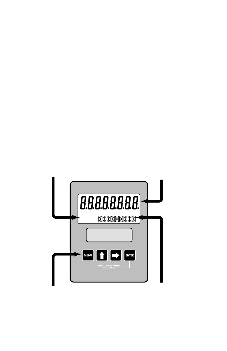
large 8 digit by .75” numeric liquid crystal display makes extended range
viewing practical. The second 8 digit by .38” alphanumeric display provides
for selectable units viewing in run mode and prompts for variables in
program mode. Finally, the user can choose between displaying rate, total,
or alternating between both rate and total.
Mode
Indicator
Programming
Keys
RUN PROGRAM
RELAY1 RELAY2
Rate / Total Display
And
Programming Choices
Units Display
And
Programming Choices
FIGURE 1
Flow Monitor
4
Page 5

SPECIFICATIONS
Power Supply Options:
1 “D” size 1.5 volt alkaline battery
Alphanumeric Rate and Total Display:
8 digit, .75” high numeric display
8 character, .38” high alphanumeric display
Fixed or toggle modes of operation for ow rate and totalizer display
Accuracy:
±0.1%
Temperature Drift: 50ppm/°C (maximum)
Mounting Classi cation:
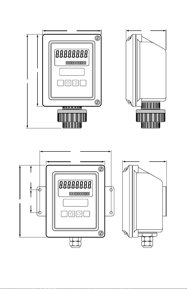
Meter Mount: Type 4X Enclosure
Remote Mount: Type 4X Enclosure
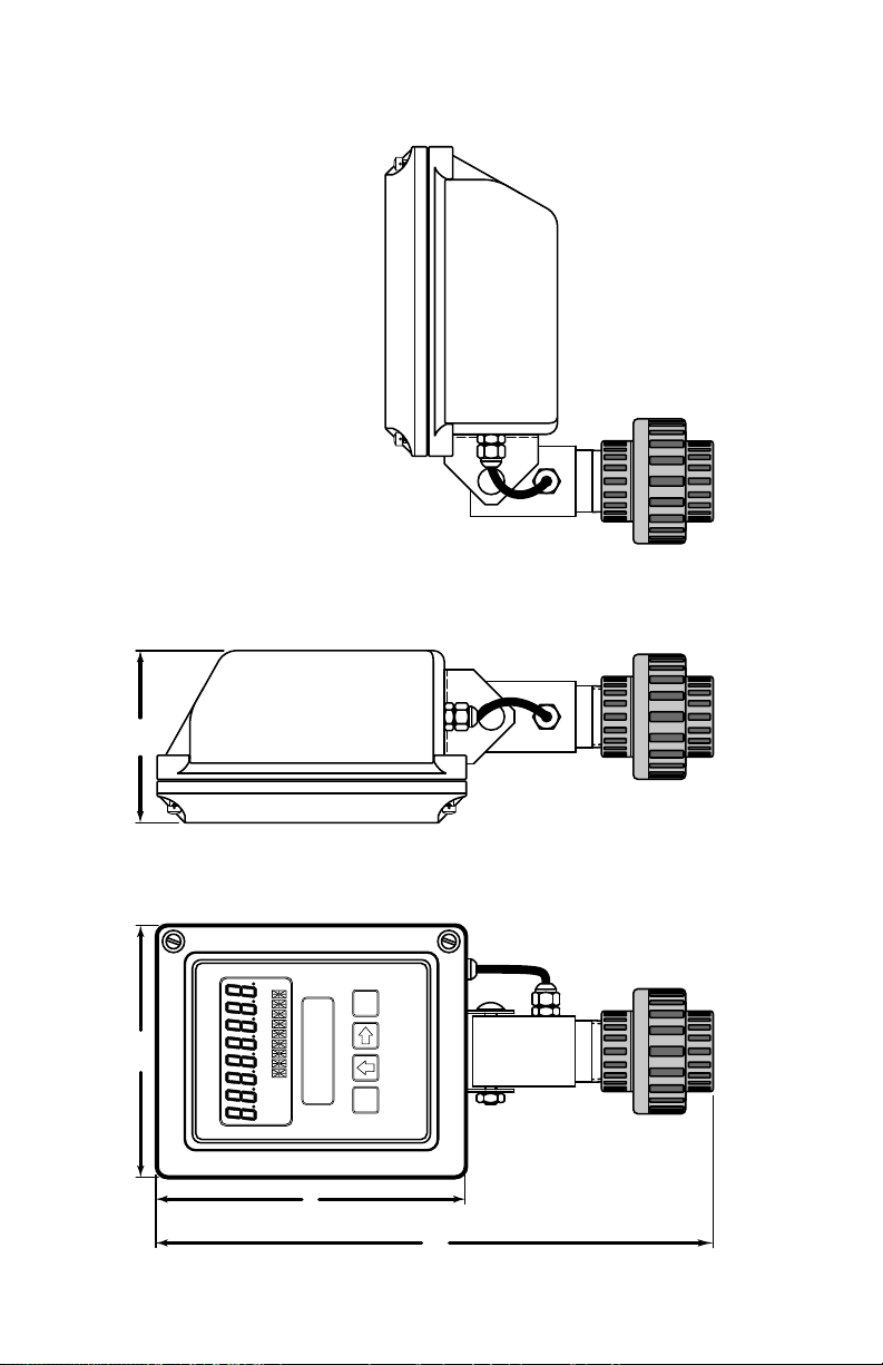
Swivel Mount: Type 4X Enclosure
Environmental:
Operating Temperature: -22 °F to +158 °F (-30 °C to +70 °C)
Humidity: 0-90% Non-condensing
Inputs:
Magnetic Pick-up Input
Frequency Range: 0 to 3500 Hz
Trigger Sensitivity: 30 mV p-p
Over Voltage Protected: ±30 VDC
Outputs:
Opto-isolated Open Collector Transistor
Maximum Voltage: 30 VDC
Pulse width: 20mS/Max rate 20Hz
Current (ON state): 0.9V drop @ 5.0 mA or 0.7V drop @ 0.1 mA
5
Page 6

OPERATING THE MONITOR
The monitor has two modes of operation referred to as the RUN mode and
the PROGRAM mode. Both the run mode and the program mode display
screen enunciators con rming the state of the monitor. A quick glance at
the lower left-hand corner of the LCD screen will con rm operating status.
Normal operation will be in the RUN mode. To access the program mode,
press the MENU button until the rst programming screen is displayed.
After programming the display with the necessary information, a lock out
feature can be turned on to prevent unauthorized access or changing the
meter’s setup parameters.
BASIC PROGRAMMING MODE
Keys:
MENU – Switches to Program mode
UP Arrow – Scrolls forward through the parameter choices and
increments numeric variables
RIGHT Arrow – Scrolls backward through the parameter choices and
moves the active digit to the right
ENTER – Used to save programming information, advance to the next
programming parameter, and in the reset process
Modes:
RUN – Normal operating mode
PROGRAM – Used to program variables into the display
If your monitor was ordered with an Omega FTB-1400 ow meter, the two
components ship from the factory calibrated as a set. If the monitor is a
replacement, the turbine’s K-factor has changed, or the monitor is being
used with some other pulse generating device, programming will be
necessary.
6
Page 7
PROGRAMMING USING PULSE OUTPUT TURBINE
FLOW METERS
Each turbine ow meter is shipped with either a K-factor value or frequency
data. If frequency data is provided, the data must be converted to a K-factor
before programming the monitor. K-factor information, when supplied, can
usually be found on the neck of the ow meter or stamped on the body. The
K-factor represents the number of pulses per unit of volume. The K-factor
will be needed to program the monitor readout.
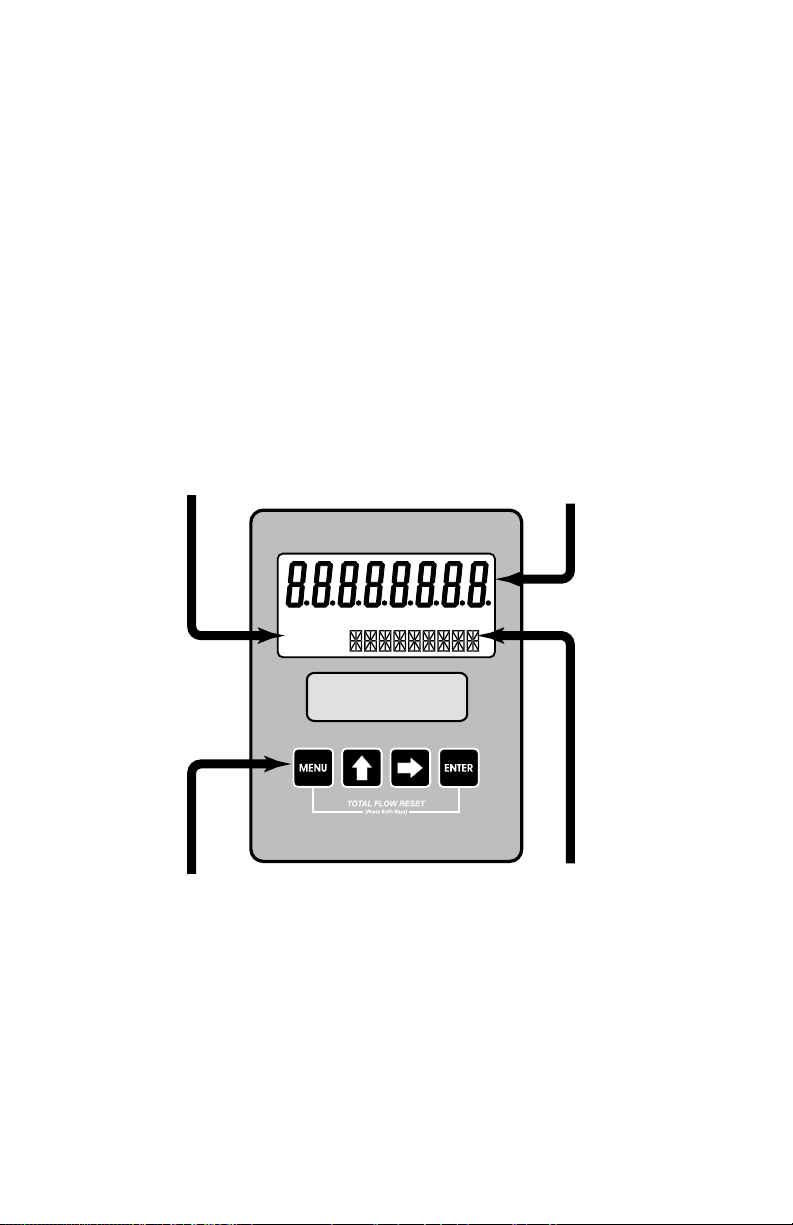
ENTER PROGRAM MODE – Change to program mode by pressing
the MENU button once. The mode indicator will change from RUN to
PROGRAM.
Mode
Indicator
Programming
Keys
RUN PROGRAM
RELAY1 RELAY2
Rate / Total Display
And
Programming Choices
Units Display
And
Programming Choices
FIGURE 2
Flow Monitor
7
Page 8

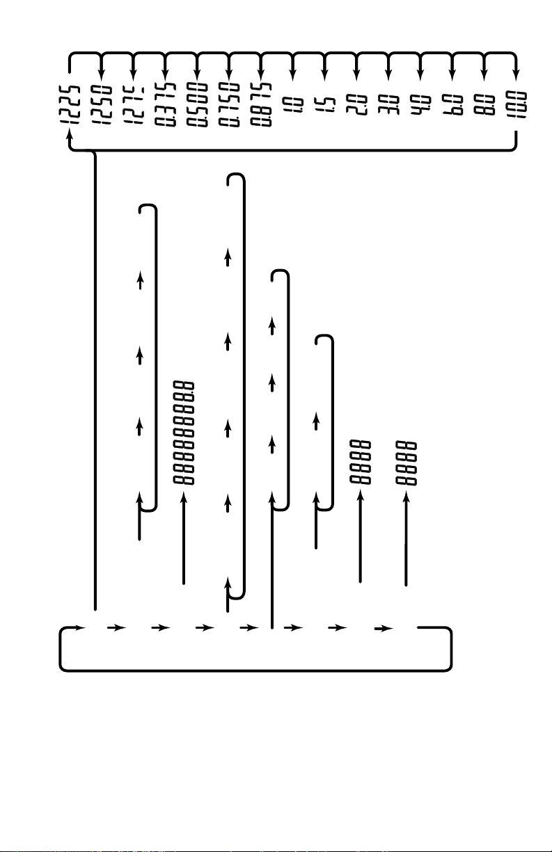
SELECT THE METER SIZE – At the METER prompt, press the UP or
RIGHT arrow keys to select the bore size of your meter. Press ENTER
button once to save meter size choice and advance to the K-factor
units selection.
NOTE: The meter connection size and the bore size are di erent. For
example, many of the 1” NPT turbines have bore sizes that range from 3⁄8”
up to 1”. Be sure to use the correct bore size or the meter will report incorrect
ows and totals.
ENTER THE METER’S K-FACTOR UNIT – Directly after the METER size
is selected, the display’s K-factor unit must be chosen. Use the UP arrow
key to select your K-factor unit. For meters calibrated in gallons, use
PUL/GAL (pulses per gallon); for meters calibrated in cubic meters, use
PUL/M3 (pulses per cubic meter), etc. Press ENTER to save the K-factor
unit and advance to the next parameter.
NOTE: Unless otherwise speci ed, Omega FTB-1400 turbine ow meters
are supplied with K-factors measured in pulses per gallon (PUL/GAL) which
will automatically convert to your desired units of measure.
NOTE: The K-factor supplied with the meter or calculated from calibration
data will be needed to complete next step.
ENTER THE METER’S K-FACTOR – To change the K-FACTOR value, use
the RIGHT arrow key and select the position of the number that you
wish to change. Using the UP arrow key, increment the display digit
until it matches the meter’s K-factor digit. Repeat this process until all
K-factor digits have been entered. Press ENTER once to save the actor
and advance to the RATE/TOTAL units selection.
8
Page 9
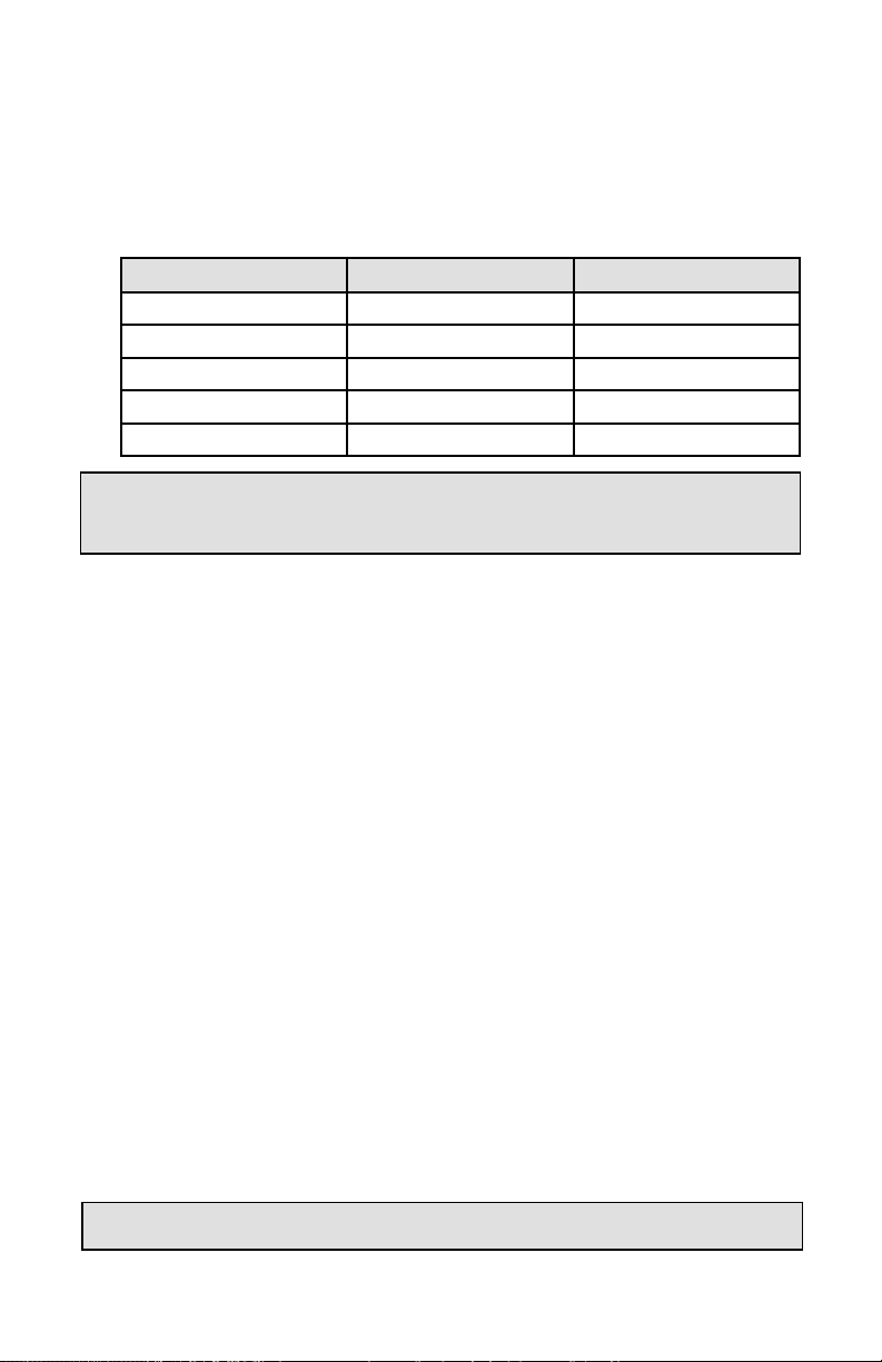
SELECT THE RATE/TOTAL UNITS OF MEASURE – The monitor allows
the choice of ve common rate/total units. The monitor shows the
current rate/total unit. If the current selection is correct, press the
ENTER key once to advance to the next parameter. To change to an
alternate unit, use the arrow keys to scroll to the desired rate unit and
press ENTER to save the choice.
Selection Rate Total
GPM/GAL Gallons per Minute Gallons
LPM/LIT Liters per Minute Liters
M3PH/M3 Cubic Meters per Hour Cubic Meters
M3PD/M3 Cubic Meters per Day Cubic Meters
BPD/BBL Oil Barrels per Day Oil Barrels
NOTE: The total unit’s output multiplier cannot be modi ed in the Simpli ed
program level. This option is reserved in the Advanced program level.
SELECT THE DISPLAY FUNCTION – The monitor can display RATE or
TOTAL or alternate between BOTH rate and total. If the current selection
is correct, press the ENTER key to advance to the next parameter. To
change to an alternate display mode, use the arrow keys to scroll to the
desired display mode and press ENTER to save the choice.
A TEST function is also available in the Display Function sub-menu. With
the test function selected, the display acts like a frequency counter and
displays the raw input frequency being supplied to the frequency input
terminals. This is very useful when troubleshooting ow problems.
TOTALIZER PULSE OUTPUT – The pulse output parameter can be
either enabled or disabled. When enabled this output generates 20mS
duration pulse for every time the least signi cant digit of the totalizer
increments. The amplitude of the pulse is dependent on the voltage
level of the supply connected to the pulse output and is limited to a
maximum 30 VDC.
PASSWORD – Password protection prevents unauthorized users from
changing programming information. Initially, the password is set to
all zeros. To change the password, simply enter any 4 digit code using
the arrow keys as previously described to enter the password value.
Pressing ENTER once will store the password and take you back to the
RST PSWD screen.
NOTE: This password will allow the operator to manually reset totals.
9
Page 10

RST PSWD – The reset password screen allows the operator to enter
any 4 digit code for the manual reset totals function.
NOTE: This reset password code will not allow the operator to enter the
programming mode.
RESET TOTAL – To reset the monitor total display, in run mode press
the MENU and ENTER simultaneously until TOTAL RST starts to ash.
The TOTAL RST will stop ashing and the display will return to the run
mode at the conclusion of the reset procedure.
STORE TOTAL – The current total can be manually stored in the
monitor’s ash memory. This procedure may be desirable prior to
replacing the battery. Press and hold the ENTER key for 2 seconds. The
display will respond with a ashing TOTALSVD and then return to the
run mode.
AUTOMATIC STORE TOTAL – The monitor is equipped with a store
total feature that works automatically, saving the current total to ash
memory once per hour and just before a low battery condition turns
the unit o .
BATTERY REPLACEMENT
Battery powered monitors use a single 1.5V, “D” size, alkaline battery. When
replacement is necessary, use a clean fresh battery to ensure continued
trouble-free operation. It is recommended that the total be saved to
memory before the battery is removed. (See STORE TOTAL above.)
Unscrew the two captive screws on the front panel to gain access to the
battery. Replace the battery being sure to observe the proper polarity, and
then re-fasten the front panel.
10
Page 11

ADDITIONAL INPUT OPTIONS
The FTB-1400 Flow Monitor is capable of receiving magnetic pick-up input
(small signal sine wave) or a contact closure input (pulse). Since Omega
FTB-1400 turbine ow meters utilize a magnetic pick-up, the FTB-1400 Flow
Monitor is shipped con gured for magnetic pick-up input. To change to a
contact closure input, remove JP2 from the top two pins and jumper them
to the bottom two pins. See Figure 3 on page 12.
11
Page 12
Keypad
Connector
J2
12345
JP2
Mag
Input
Pulse
Inuput
20 mS Pulse
12
+30 VDC (Max)
10K
123456
-
+
Pulse Out Freq. In4-20 mA
FIGURE 3
Wiring Diagram
+ -+
N/C N/C
TB1
-
Magnetic Pickup
Page 13
BPD/BBL
M3PH/M3 M3PD/M3
PUL/GAL PUL/FT3PUL/LTRPUL/M3
LPM/LIT
GPM/GAL
BOTH TOTAL RATE TEST
PULS ON PULS OFF
IO/SETUP
METER
13
K Factor Units
K FACTOR
Units
Basic Programming Menu
DSP
FIGURE 4
Pulse Output
PASSWORD
RST PSWD
Page 14
MOUNTING OPTIONS
8.93"
7.00"
5.75"
RUN PROGRAM
RELAY1 RELAY2
MENU ENTER
METER DISPLAY
7.00"
5.75"
3.93"
4.30"
7.00"
14
2.40"
TYP.
2.25"
TYP.
RUN PROGRAM
RELAY1 RELAY2
MENU ENTER
REMOTE DISPLAY
Page 15
3.93"
5.75"
SWIVEL MOUNT
RUN PROGRAM
RELAY1 RELAY2
MENU ENTER
7.00"
12.25"
15
Page 16
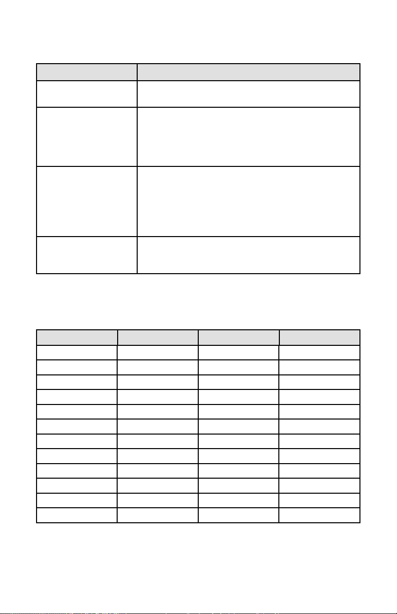
TROUBLESHOOTING GUIDE
Trouble Remedy
No LCD Display
No Rate or Total
Displayed
Flow Rate Display
Interprets Reading
Constantly
Flow Rate Indicator
Bounces
• Check battery voltage. Should be 1.5 Vdc. Replace if low
or bad.
• Check connection from meter pick-up to display input
terminals.
• Check turbine meter rotor for debris. Rotor should spin
freely.
• Check programming of ow monitor.
• This is usually an indication of external noise. Keep all
AC wires separate from DC wires.
• Check for large motors close to the meter pick-up.
• Check for radio antenna in close proximity.
• Try disconnecting the pick-up from the monitor pig tail.
This should stop the noise.
• This usually indicates a weak signal. Replace pick-up
and/or check all connections.
• Examine K-factor.
DEFAULT K-FACTOR VALUES
Meter Size Default K-factor Lower Limit Upper Limit
0.375 20,000 16,000 24,000
0.500 13,000 10,400 15,600
0.750 2,750 2,200 3,300
0.875 2,686 2,148 3,223
1.000 870.0 696.0 1,044
1.500 330.0 264.0 396.0
2.000 52.0 41.6 62.0
3.000 57.0 45.6 68.0
4.000 29.0 23.2 35.0
6.000 7.0 5.6 8.0
8.000 3.0 2.4 4.0
10.000 1.6 1.3 2.0
16
Page 17

PART NUMBERING INFORMATION
FTB - 1400 - X D
Mounting Style
M - Meter Mount
R - Remote Mount
S - Swivel Mount
REPLACEMENT PARTS
Component Part Number
Keypad B260713
Battery B280601
Battery Tie Wrap B228036
Pick-up Cable B222-121
Desiccant Bag B260630
PVC Union B220016
PVC Reducer Bushing B220056
Rubber Washer B228207
Steel Lock Washer B220018
PCB Shield (battery units) B280603
Desiccant Shield B280680
Cord Grip B220103
17
Page 18
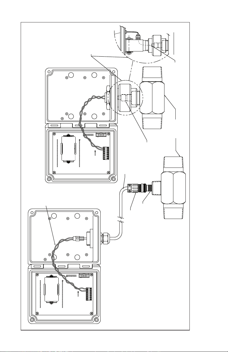
SWIVEL MOUNT
METER MOUNT OR
METER MOUNT
OR SWIVEL MOUNT
SCALE: .75 = 1
SWIVEL MOUNT DETAIL
WIRE HARNESS
FTB-1400 SERIES
TURBINE METER
WIRE HARNESS
-+
+ -
REMOTE CABLE WITH STRAIGHT AMPHENOL
CONNECTOR OR REMOTE CABLE WITH
MAGNETIC PICK-UP
90° AMPHENOL CONNECTOR
INSTALLATION DRAWING
MAGNETIC PICKUP
10 FT. TO MAX. 100 FT.
STRAIGHT TO TURBINE
CONNECTOR 90° OR
OPTIONAL AMPHENOL
18
Page 19

WARRANTY/ DISCLAIMER
OMEGA ENGINEERING, INC. warrants this unit to be free of defects in materials and
workmanship for a period of 13 months from date of purchase. OMEGA’s WARRANTY adds
an additional one (1) month grace period to the normal one (1) year product warranty to
cover handling and shipping time. This ensures that OMEGA’s customers receive maximum
coverage on each product.
If the unit malfunctions, it must be returned to the factory for evaluation. OMEGA’s Customer
Service Department will issue an Authorized Return (AR) number immediately upon phone or
written request. Upon examination by OMEGA, if the unit is found to be defective, it will be
repaired or replaced at no charge. OMEGA’s WARRANTY does not apply to defects resulting
from any action of the purchaser, including but not limited to mishandling, improper
interfacing, operation outside of design limits, improper repair, or unauthorized modification.
This WARRANTY is VOID if the unit shows evidence of having been tampered with or shows
evidence of having been damaged as a result of excessive corrosion; or current, heat, moistur e
or vibration; improper specification; misapplication; misuse or other operating conditions
outside of OMEGA’s control. Components in which wear is not warranted, include but are not
limited to contact points, fuses, and triacs.
OMEGA is pleased to offer suggestions on the use of its various products. However,
OMEGA neither assumes responsibility for any omissions or errors nor assumes
liability for any damages that result from the use of its products in accordance with
information provided by OMEGA, either verbal or written. OMEGA warrants only
that the parts manufactured by the company will be as specified and free of
defects. OMEGA MAKES NO OTHER WARRANTIES OR REPRESENTATIONS OF ANY
KIND WHATSOEVER, EXPRESSED OR IMPLIED, EXCEPT THAT OF TITLE, AND ALL
IMPLIED WARRANTIES INCLUDING ANY WARRANTY OF MERCHANTABILITY AND
FITNESS FOR A PARTICULAR PURPOSE ARE HEREBY DISCLAIMED. LIMITATION OF
LIABILITY: The remedies of purchaser set forth herein are exclusive, and the total
liability of OMEGA with respect to this order, whether based on contract, warranty,
negligence, indemnification, strict liability or otherwise, shall not exceed the
purchase price of the component upon which liability is based. In no event shall
OMEGA be liable for consequential, incidental or special damages.
CONDITIONS: Equipment sold by OMEGA is not intended to be used, nor shall it be used: (1)
as a “Basic Component” under 10 CFR 21 (NRC), used in or with any nuclear installation or
activity; or (2) in medical applications or used on humans. Should any Product(s) be used in or
with any nuclear installation or activity, medical application, used on humans, or misused in
any way, OMEGA assumes no responsibility as set forth in our basic WARRANTY/ DISCLAIMER
language, and, additionally, purchaser will indemnify OMEGA and hold OMEGA harmless from
any liability or damage whatsoever arising out of the use of the Product(s) in such a manner.
Direct all warranty and repair requests/inquiries to the OMEGA Customer Service Department.
RETURN REQUESTS/INQUIRIES
BEFORE RETURNING ANY PRODUCT(S) TO OMEGA, PURCHASER MUST OBTAIN AN
AUTHORIZED RETURN (AR) NUMBER FROM OMEGA’S CUSTOMER SERVICE DEPARTMENT
(IN ORDER TO AVOID PROCESSING DELAYS). The assigned AR number should then be
marked on the outside of the return package and on any correspondence.
The purchaser is responsible for shipping charges, freight, insurance and proper packaging to
prevent breakage in transit.
FOR WARRANTY
the following information available BEFORE
contacting OMEGA:
1. Purchase Order number under which
the product was PURCHASED,
2. Model and serial number of the product
under warranty, and
3. Repair instructions and/or specific
problems relative to the product.
OMEGA’s policy is to make running changes, not model changes, whenever an improvement is possible.
This affords our customers the latest in technology and engineering.
OMEGA is a registered trademark of OMEGA ENGINEERING, INC.
© Copyright 2008 OMEGA ENGINEERING, INC. All rights reserved. This document may not be copied, photocopied,
reproduced, translated, or reduced to any electronic medium or machine-readable form, in whole or in part, without
the prior written consent of OMEGA ENGINEERING, INC.
19
RETURNS, please have
FOR NON-WARRANTY REPAIRS,
OMEGA for current repair charges. Have the
following information available BEFORE
contacting OMEGA:
1. Purchase Order number to cover the
COST of the repair,
2. Model and serial number of the
product, and
3. Repair instructions and/or specific problems
relative to the product.
consult
Page 20

Where Do I Find Everything I Need for
Process Measurement and Control?
OMEGA…Of Course!
Shop online at omega.com
TEMPERATURE
Thermocouple, RTD & Thermistor Probes, Connectors, Panels & Assemblies
Wire: Thermocouple, RTD & Thermistor
Calibrators & Ice Point References
Recorders, Controllers & Process Monitor s
Infrared Pyrometers
PRESSURE, STRAIN AND FORCE
Transducers & Strain Gage s
Load Cells & Pressure Gages
Displacement Transducers
Instrumentation & Accessories
FLOW/LEVEL
Rotameters, Gas Mass Flowmeters & Flow Computers
Air Velocity Indicators
Turbine/Paddlewheel System s
Totalizers & Batch Controllers
pH/CONDUCTIVITY
pH Electrodes, Testers & Accessories
Benchtop/Laboratory Meters
Controllers, Calibrators, Simulators & Pumps
Industrial pH & Conductivity Equipment
SM
DATA ACQUISITION
Data Acquisition & Engineering Softwar e
Communications-Based Acquisition System s
Plug-in Cards for Apple, IBM & Compatibles
Datalogging System s
Recorders, Printers & Plotters
HEATERS
Heating Cabl e
Cartridge & Strip Heaters
Immersion & Band Heaters
Flexible Heaters
Laboratory Heaters
ENVIRONMENTAL
MONITORING AND CONTROL
Metering & Control Instrumentation
Refractometers
Pumps & Tubing
Air, Soil & Water Monitor s
Industrial Water & Wastewater Treatment
pH, Conductivity & Dissolved Oxygen Instrument s
M-4523/0310
 Loading...