

Page 1
Magnetic
Pick-Up
Meter Body
Retaining Ring
Inlet Flow
Straightener
Conduit
Adapter
Retaining
Ring
Outlet Flow
Straightener
Turbine Assembly
ECONOMICAL LIQUID
TURBINE FLOW METERS
FTB-1400 Series
Standard
U Cost-Effective Solution
for Turbine Flowmeter
Applications
U Rugged 316 Stainless Steel
Construction Offers Long
Service Life in Severe
Operating Environments
U Accurate and Repeatable
Flow Measurement
U Installation in Pipe Sizes
U NIST Calibration
from
1
⁄2 to 2"
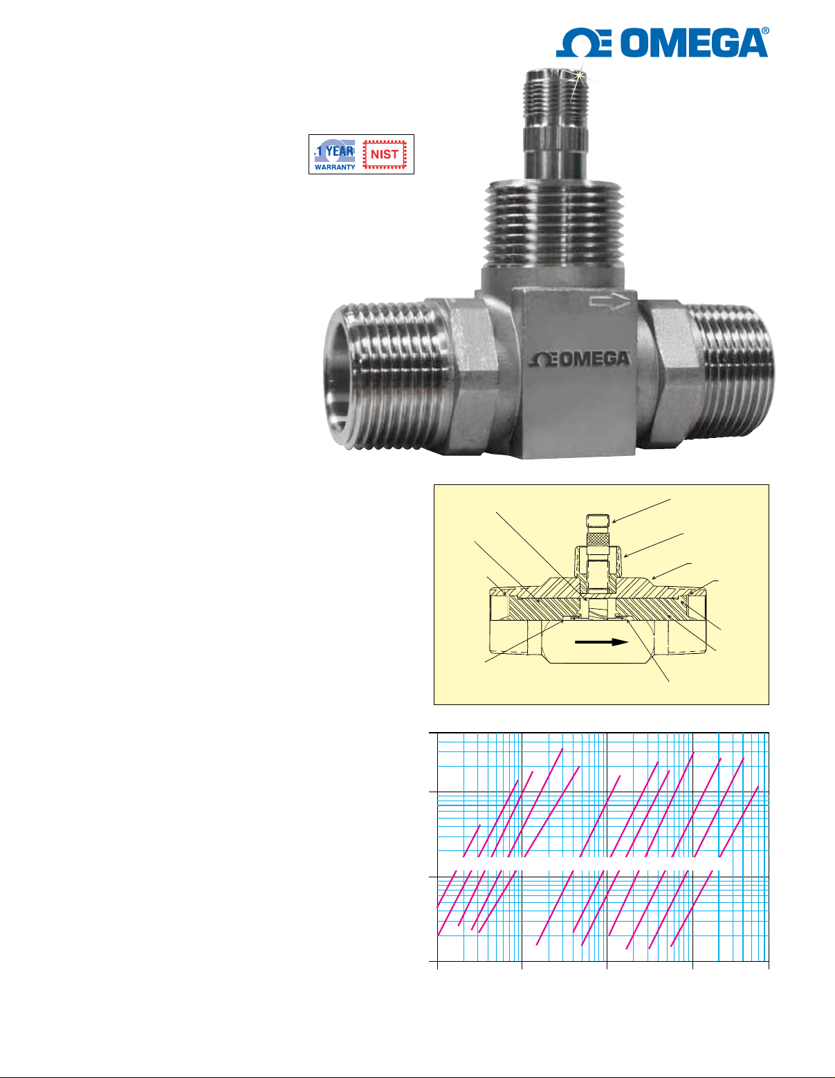
FTB-1425, shown
smaller than actual size.
The OMEGA® FTB-1400 turbine flowmeter is
designed to meet the demands of the most rigorous
flow measurement applications. Originally developed
for the secondary oil recovery market, the FTB-1400
is an ideal meter for liquid flow measurement on or
off the oilfield. The meter features a 316 Stainless
Steel housing and rotor support, CD4MCU Stainless
Steel rotor, and abrasion-resistant tungsten carbide
rotor shaft and journal bearings. These materials help
the meter to maintain accuracy and mechanical
integrity when measuring the corrosive and abrasive
fluids found in many industries.
Fluid entering the meter first passes through an inlet
flow straightener that reduces its turbulent flow
pattern. Fluid then passes through the turbine,
causing the turbine to rotate at a speed proportional
to fluid velocity. As each turbine blade passes through
the magnetic field generated by the meters magnetic
pick-up, an AC voltage pulse is generated. These
pulses provide an output frequency that is proportional
to volumetric flow.
SPECIFICATIONS
Accuracy: ±1% of reading for 1" and larger, ±1% of
reading over the upper 70% of the measuring range
1
⁄2" meters
for
Repeatability: ±0.1%
Magnetic Pickup: 30 mV/P-P
Materials of Construction
Body: 316 Stainless Steel
Rotor: CD4MCU Stainless Steel
Rotor Support: 316 Stainless Steel
Rotor Shaft: Tungsten carbide
Turndown Ratio: 10:1
Calibration: Water (NIST traceable calibration)
Pressure Rating: 5000 psi (maximum)
Turbine Temperature: -101 to 177°C (-150 to 350°F);
-101 to 232°C (-150 to 450°F) (with “-HT” option)
End Connections: NPT, BSPP optional
Rotor and
Rotor Shaft
*Upstream
Rotor Support
*Retaining
Ring
*Thrust
Ball
Note: * Indicates Parts Contained in Repair Kits
50
Pressure Drop vs. Flow Rate
Magnetic
Pick-up
Conduit
Adaptor
Meter Body
*Bearing
Retaining
Ring
Groove
Retainer
Pins
*Downstream
Rotor Support
10
3/4"
3/8"
1/2"
7/8"
1"
1-1/2"
2"
3"
4"
6"
10"
8"
1
PSID Pressure Drop
.1
110 100 1,000 8,000
(34) (343) (3429) (34,286) (274,286)
Flow Rate GPM (BPD)
F-49
Page 2
Typical K-Factor Curve (Pulses per Gallon)
K-Factor
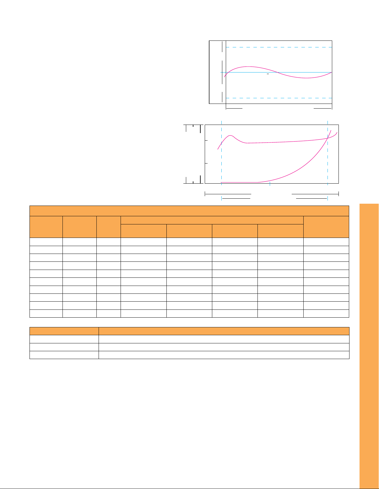
The K-Factor represents the number of output pulses
transmitted per gallon of fluid passing through the
turbine meter. Each turbine has a unique K-Factor.
However, turbine meters are not functionally consistent
throughout the full flow range of the meter.
There are several forms of “friction” inherent in turbine
meters that retard the rotational movement of the turbine
rotor. These frictional forces include: magnetic drag,
created by electromagnetic force of pickup transducers;
mechanical drag, due to bearing friction; and viscous
drag, produced by flowing fluid. See charts on right.
As flow increases, the frictional forces are minimized
and the free-wheeling motion of the turbine rotor
becomes more linear (proportional to flow). The
K-Factor becomes relatively constant and linear
throughout the balance of the linear flow range.
This is approximately a 10:1 turndown ratio from the
maximum flow rate down to the minimum flow rate.
To Order
End
Model No.
FTB-1411
FTB-1412
FTB-1413
FTB-1421
FTB-1422
FTB-1423
FTB-1424
FTB-1425
FTB-1431
FTB-1441
Accessories
Model No. Description
FTB-1400-CABLE
FTB-1400-90CABLE
FTB-1400-MP
Connection
1/2 NPT
1/2 NPT
1/2 NPT
1 NPT
1 NPT
1 NPT
1 NPT
1 NPT
11/2 NPT
2 NPT
BORE
3/8"
1/2"
3/4"
3/8"
1/2"
3/4"
7/8"
1"
1-1/2"
2" Low
LPM GPM Barrels/Day
2.3 to 11.3 0.6 to 3 20 to 100 18,000 76 (3)
2.8 to 28 0.75 to 7.5 25 to 250 13,000 76 (3)
7.6 to 56.7 2 to 15 68 to 515 3300 76 (3)
2.3 to 11.3 0.6 to 3 20 to 100 18,000 76 (3)
2.8 to 28 0.75 to 7.5 25 to 250 13,000 76 (3)
7.6 to 56.7 2 to 15 68 to 515 3300 76 (3)
11.3 to 113 3 to 30 100 to 1000 3100 101 (4)
18.9 to 189 5 to 50 170 to 1700 870 101 (4)
56.8 to 681 15 to 180 515 to 6000 330 152 (6)
56.8 to 681 15 to 180 515 to 6000 330 152 (6)
3 m (10') cable assembly with 2-pin connector (required for remote display)
3 m (10') cable assembly with 2-pin 90º connector (required for remote display)
Replacement standard magnetic pick-up
Typical K-Factor Curve (Pulses Per Gallon)
+1%
+%
K
U
S
S
E
R
P
K-Factor
Pul/Gal
-
F
A
C
T
O
R
O
R
D
E
R
AVG. K-FACTOR (K)
-%
LINEARITY (DESIGN DEVIATION)
-1%
1" AND LARGER TURNDOWN APPROX. 10:1
½" TURNDOWN APPROX. 3:1
100%
50%
% OF VALUE AT FLOW RATE
K-FACTOR (CYCLES/GALLON)
OUTPUT FREQUENCY (CYCLES/SEC)
0% 10% 50% 100%
K-FACTOR (PULSES/GALLON)
FULL FLOW RANGE
LINEAR FLOW RANGE
Range
L
A
S
G
/
E
S
Lay Length
O
L
L
F
(
P
U
P
)
N
mm (inch)
Comes complete with operator’s manual and 5 point NIST calibration certificate for water. Cable with connector sold separately.
Cable/connector are required for operation.
For units with high temp magnetic pulse output, add suffix “-HT” to model number, consult Flow Engineering for price
(not available on “-AMP” models).
For units with amplified pulse output, add suffix
For units with BSPP threads, add suffix “BSP” to model number for additional cost.
Ordering Examples: FTB-1424, 1 NPT stainless turbine.
FTB-1411, ½ NPT stainless turbine and DPF701, digital panel meter for rate of total display, FTB-1400-CABLE, 3 m (10') cable assembly with
2-pin connector. For details on DPF701 meter, visit omega.com/dpf700 for details.
“-AMP” to model number consult Flow Engineering for price (not available on “-HT” models).
F-50
 Loading...