

Page 1
Page 2
SPECIFICATIONS StepOne
AboutThisManual:PLEASEREADTHEENTIREMANUALPRIORTOINSTALLINGORUSINGTHISPRODUCT.
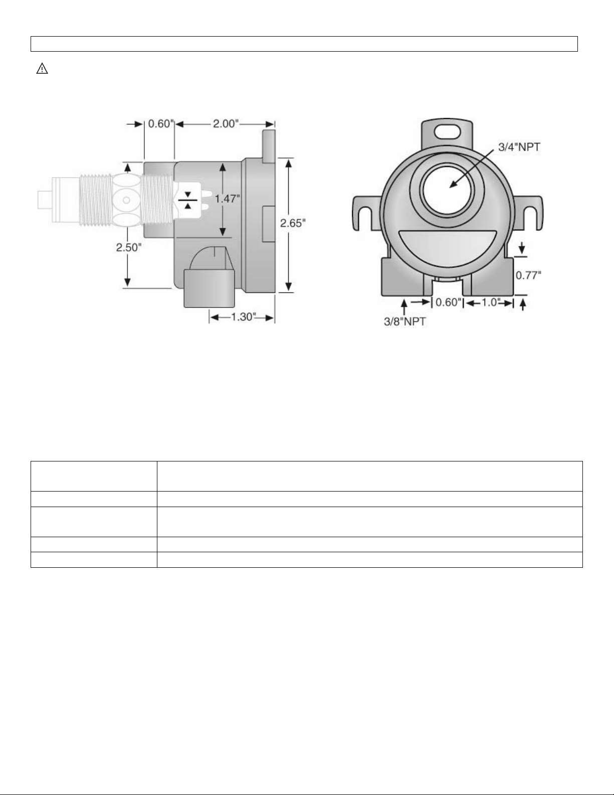
Dimensions:
SideView: TopView:
Components:Checktomakesurethatallthepartsareincludedinthekitbeforeproceeding.Oneflowswitch
fitting(FT‐50series)includesthefollowingparts:
1–FlowSwitchFitting
FT‐51‐PolypropyleneFitting
FT‐52‐PolyvinylideneFluorideFitting
1–O‐ringforsensor
Specifications:
Housingmaterials: FT‐51:Polypropylene
FT‐52:PolyvinylideneFluoride
Insertionport: Locatedonbottom
Temperaturerating: F:32to194°
C:0to90°
Pressurerating: 150psi@25°C,derated@1.644psiper°Cabove25°C
Connections: 3/8”NPT,Female
Compatibility:TheFT‐50seriesflowswitchfittingiscompatiblewiththefollowingseriesofflowswitches
fromOmegaEngineering:
FST‐210‐R
FST‐211‐SPST
FST‐212‐R
FST‐212‐SPST
Page 3
INSTALLATION StepTwo
MakeaFail‐SafeSystem:Designafail‐safesystemthat accommodatesthepossibility ofsensororpower
failure.Incritical applications, Flowline recommends the use of redundant backup systemsandalarmsin
additiontotheprimarysystem.
AbouttheFlowSwitch Fitting:Omega Engineering’sFlowSwitchFittingisdesignedforusewiththeOmega
EngineeringThermal Dispersion liquid flowswitch (FST‐200 series).A veryeconomical and accurate method
ofsensingflowiscreatedwhenusingtheFT‐50serieswiththeFST‐200seriesflowswitch.Liquidsfrom0.4to
1.2 SG and a 1 to 300 cp
monitored.The3/8”NPTfemaleinletsallowforeasyconnectionstolinesizesfrom1/8”to½”.
can be monitored.Also,pulsating flows from 10 to 100 pulses per minute can be
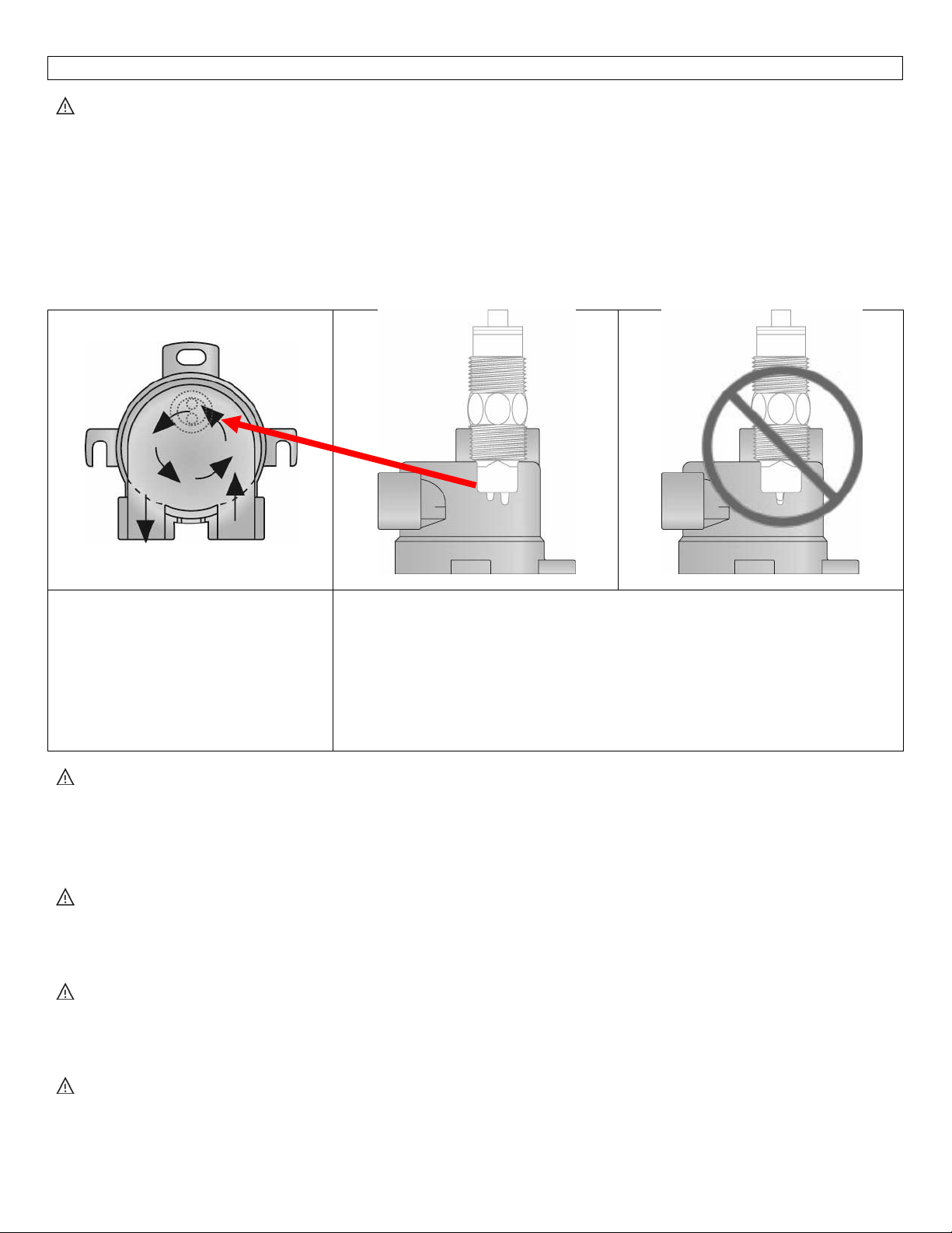
FT‐50 series unique design creases
a vortex inside its chamber.The
vortex uses its stored energy to
create a flow pattern.This design
isidealfor pulsating flows and low
flowconditions.
User’sResponsibilityforSafety:FLOWLINEmanufacturesseveralmodelsofflowswitchesandliquidlevel
sensors, controller and mounting systems.It is the user’s responsibility to select components that are
appropriatefor the application, install it properly, perform tests of the installed system,and maintain all
components.Thefailuretodo
Proper Installation and Handling:Use a proper sealant with all installations.Never over tighten the
sensor within the fitting beyond a maximum of 80 inch‐pounds torque.Always check for leaks prior to
systemstart‐up.
Insertthe FT50 into the ¾” NPT sensor port taking care to orientate the
twotemperatureprobesperpendiculartotheflowofthevortex.
Note:Besuretoremove/bleedallairfromtheinsideofthe chamberfor
operationoftheflowswitch.
Note:Theflowswitchfittingcanbemountedinanyorientation.
socouldresultinpropertydamageorseriousinjury.
MaterialCompatibility:Theflowswitchfittingisavailable intwodifferentwettedmaterials.ModelFT‐51
ismadeofPP(polypropylene,apolyolefin).ModelFT‐52ismadeofPVDF(PolyvinylideneFluoride).Make
surethattheapplicationliquidsarecompatiblewiththematerialsthatwillbewetted.
FlammableorExplosiveApplications: TheFT‐50seriesfitting maybeusedwithinflammable orexplosive
applications. In hazardous applications, use redundant measurement and control points, each having a
differentsensingtechnology.
Page 4
 Loading...