

Page 1
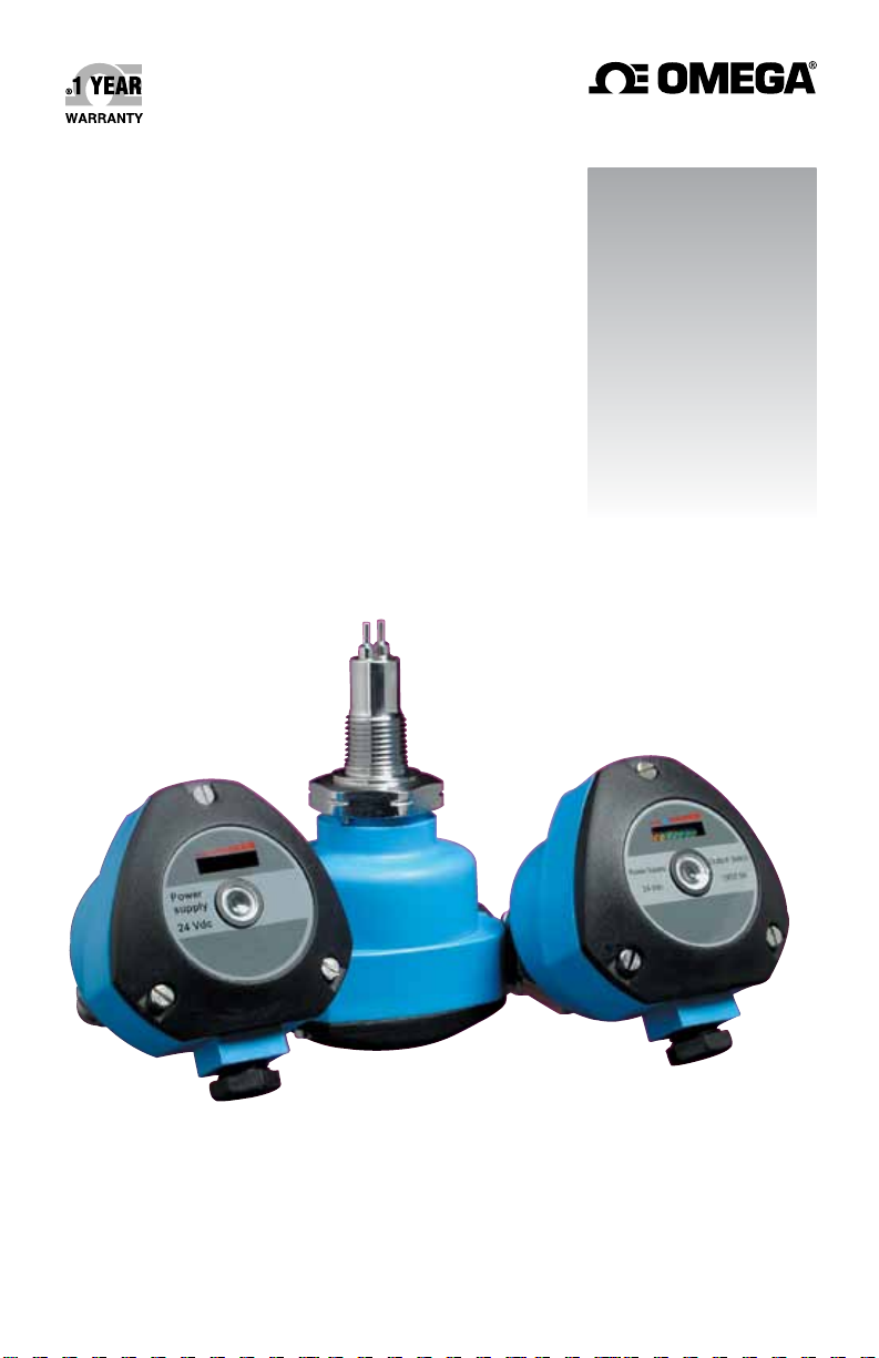
User’s Guide
Shop online at
omega.com
e-mail: [email protected]
For latest product manuals:
www.omegamanual.info
SM
FSW-6000/FSW-7000 Series
Thermal Dispersion
Flow Switches
Page 2

omega.com [email protected]
Servicing North America:
U.S.A.: Omega Engineering, Inc.
Toll-Free: 1-800-826-6342 (USA & Canada only)
Customer Service: 1-800-622-2378 (USA & Canada only)
Engineering Service: 1-800-872-9436 (USA & Canada only)
Tel: (203) 359-1660 Fax: (203) 359-7700
e-mail: [email protected]
For Other Locations Visit omega.com/worldwide
The information contained in this document is believed to be correct, but OMEGA accepts no liability for any errors it contains,
and reserves the right to alter specifications without notice.
Page 3

Contents
Introduction
Models&Dimensions .........................................5
WiringDiagram ..............................................6
FSWRelayStatusGuide ......................................8
Pre-Installation ..............................................9
Installation .................................................10
Calibration .................................................11
Handling ..................................................13
TechnicalSpecifications ......................................14
TroubleShooting ............................................16
.................................................4
www.omega.come-mail:[email protected]
03
Page 4
®
Introduction
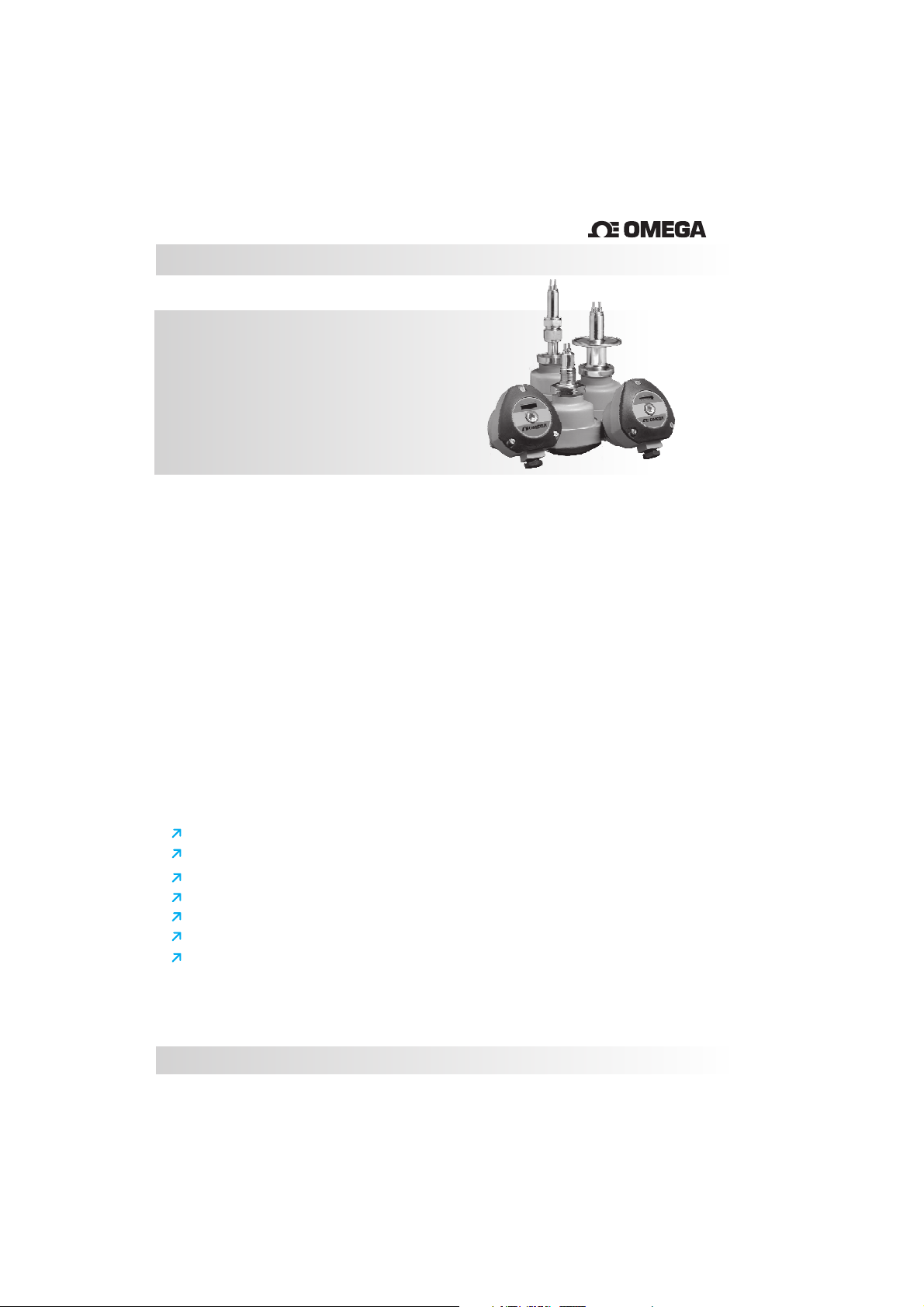
FSW6000/7000
ThermalDispersionFlow
SwitchMonitor
The
FSW series of thermal flow switches is designed to monitor flow status of liquids and
gases
and can also be usedto detect level.
Achain of 8LED's gives the user a visual indicationof the flow status of the switch. There are
two red LEDs that indicatewhether or not the unit has detected flow, a yellow LED to indicate
the set point (for increasing or decreasing flows) and 5 green LEDs that indicate the amount
of flow beyond the set point of the unit. The FSW also includes a di-chromatic (red/green)
LED which showsthe switch point statusof the unit.
The sensing element and connection of the FSW are made with 316 S.S. and can be coated
when necessary .The enclosure is offered in either nylon oraluminum.
All models can be ordered with a great variety of threaded, flange, or sanitary process
connections as wellas ECTFE or epoxycoating for aggressive mediums.
For ECTFE coating we recommend that the switches are made with flanged connections or
a minimum of1” threaded connection.
Features
Simpletoinstall.
Excellentlowflowsensitivity.
Nomovingparts-maintenancefreereliabity.
Canbecoatedforaggressivemediums.
Maximumworkingpressureof1450PSI(100bar).
Fastresponsetimeforfloworlevel(Adjustablefrom1-10seconds).
Avaliableinthreaded,sanitaryandadjustableinsertionlengthconnections.
04
Page 5
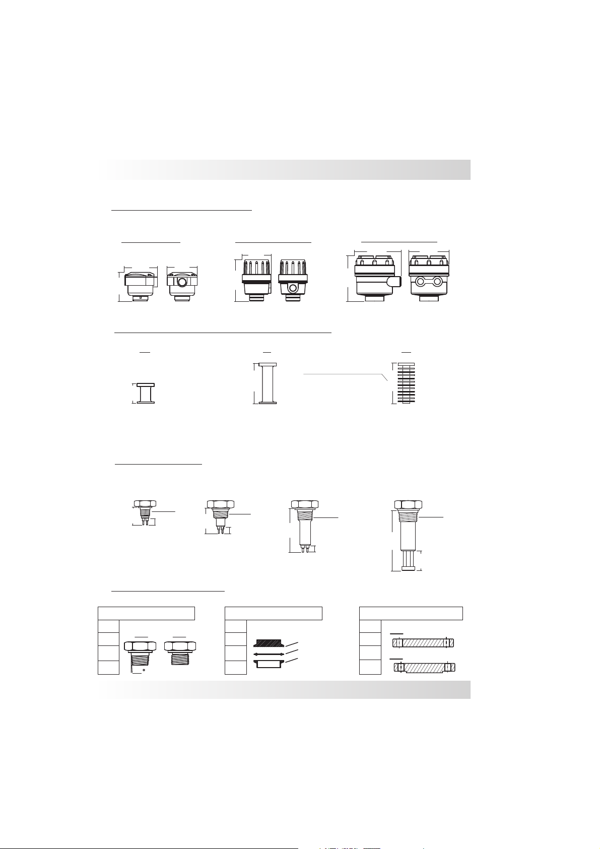
MountingOptionsforFSW
ModelsandDimensions
NylonHousing
89mm
76mm
80mm
Aluminum Housing
89mm
126mm
ExtendedNecksforHigherTemperatures
UltraHightemp.neckw/
heatdissipatingrings
100mm
50mm
MT-Medium (upto120ºC)
A
T-HighTemperature(upto150ºC)
Temperature
HT-UltraHightemperature(upto250ºC)
InsertionLength
FSWw/insertion
lengthof35mm
½” NPT
12mm
35mm
FSWw/insertion
lengthof50mm
1” NPT
12mm
50mm
Otherinsertionlengthsareavailableuponrequest
FSWw/insertion
lengthof75mm
3/4” NPT
75mm
12mm
AluminumHousing
130mm
130mm
FSWforUltraHightemperaturew/
minimuminsertionlengthof100mm
HTATMT
100mm
100mm
118mm
1” NPT
45mm
ProcessConnections
ThreadedConnections
½”
3/4”
”
1
1½”
NPT
1,75
BSP
www.omega.come-mail:[email protected]
Tri-ClampConnection FlangeConnections
1”
1½”
2”
2½”
TCConnection
RubberSeal
ProcessConnection
1”
1½”
2”
2½”
RF
FF
ANSI150#
ANSI300#
05
Page 6
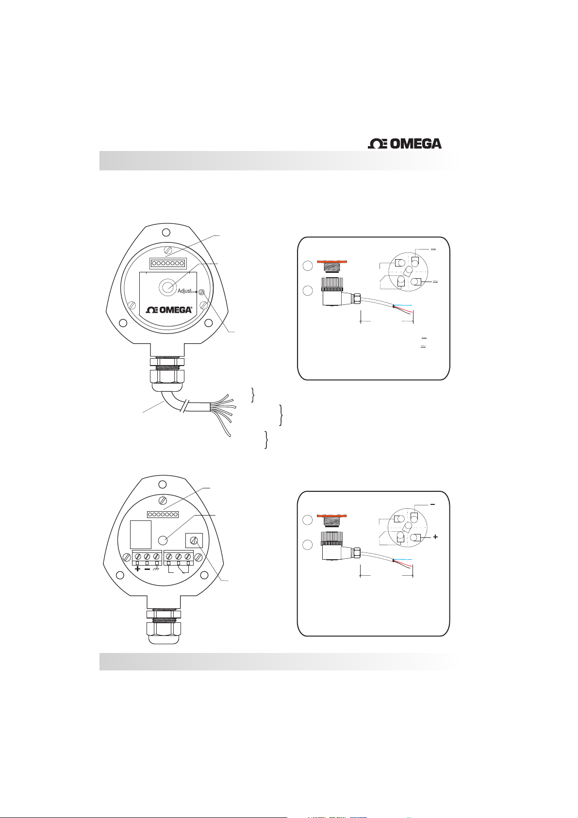
WiringDiagram
FSW6000- ACPowered
Bargraph(B1)
®
NylonHousing
M12ConnectorOptional
StandardConnectionw/
2metersofCable
FSW7000-DCPowered
Adjust
Adjust
CentralLED(L1)
(Red/Green)
Adjust(P1)
Red
Black
Green(NC)
Blue(common)
White(NO)
Greenand
Yellow
orsolid Yellow
Bargraph(B1)
CentralLED(L1)
(Red/Green)
Power
Supply
Ground
1
2
Connector
12mm
Contacts
M12ConnectorOptional
1
2
NOorNC
contact
1
-PowerSupply
23-NOContact
4-NCContact
5-
NOorNC
contact
2
3
5
4
2000mm
PowerSupply
Common
2
3
5
4
1
_
1
+
06
_
+
Adjust(P1)
1
-PowerSupply(+)
2- (-)
PowerSupply
3-Ground
4-NOContact
Connector
12mm
2000mm
1
-PowerSupply(+)
2- (-)
PowerSupply
3-NOContact
4-NCContact
5-
Common
5-Common
6-
NCContact
Page 7
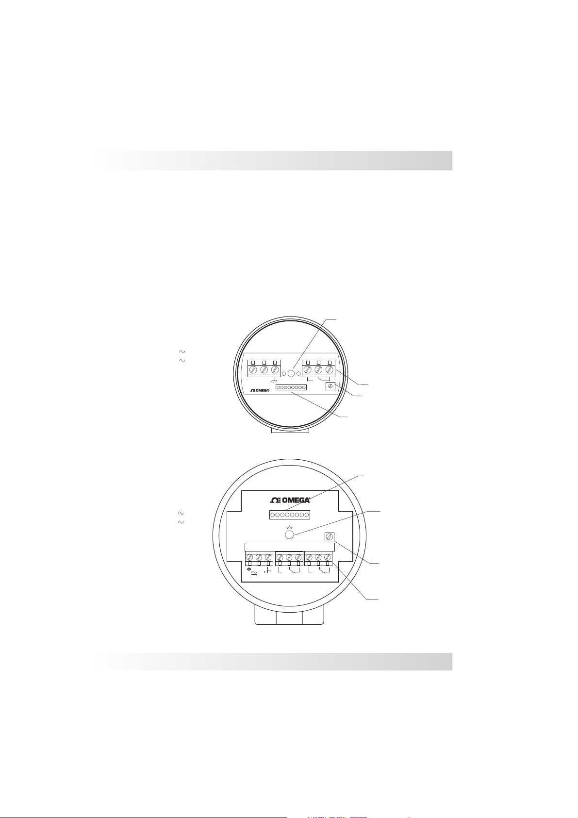
FSW6000/7000with
Aluminum-Housing
(P1)-SetPointPotentiometer Adjust
WiringDiagram
(B1)-8LED´s
(L1)-CentralLED-Green:Withflow
Small
1
-PowerSupply(+)
2- (-)
PowerSupply
3-Ground
4-NOContact
5-Common
6-
NCContact
Bargraph
Aluminum
:RedLED
YellowLED
GreenLED
Red:Noflow
(
)
(
)
Large Aluminum
(
-PowerSupply(+)
1
PowerSupply
2- (
3-Ground
4-NOContact
5-Common
6-
NCContact
7-NOContact
8-Common
9-NCContact
)
(
)
-)
1 2 3 4 5 6
_
+
100%0
Flow
1 234
+
-
5 6
7 9
Adjust
8
CentralLED(L1)
Red/Green
1SPDT
Adjust(P1)
Bargraph(B1)
Bargraph(B1)
2SPDT
CentralLED(L1)
Red/Green
Adjust(P1)
www.omega.come-mail:[email protected]
07
Page 8
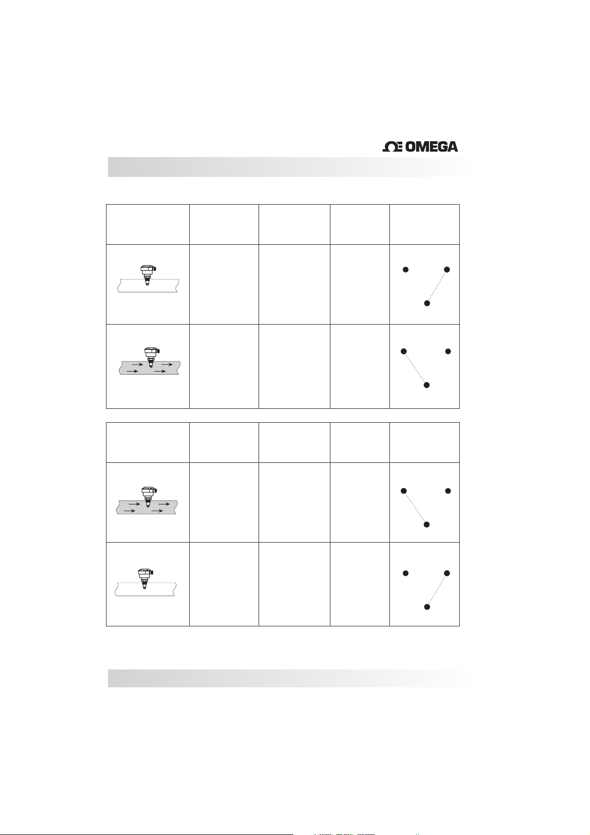
FSWRelayStatusGuide
®
Application
FSH
Application
FSL
Condition
Normal
Alarm
Condition
Normal
LEDStatus
RED
GREEN
LEDStatus
GREEN
SetPoint
OFF
ON
SetPoint
ON
FSWSPDT
Status
NO(4)
C(5)
NO(4)
C(5)
FSWSPDT
Status
NO(4)
NC(6)
NC(6)
NC(6)
08
Alarm
RED
OFF
NO(4)
C(5)
NC(6)
C(5)
Page 9
Pre-Installation
®
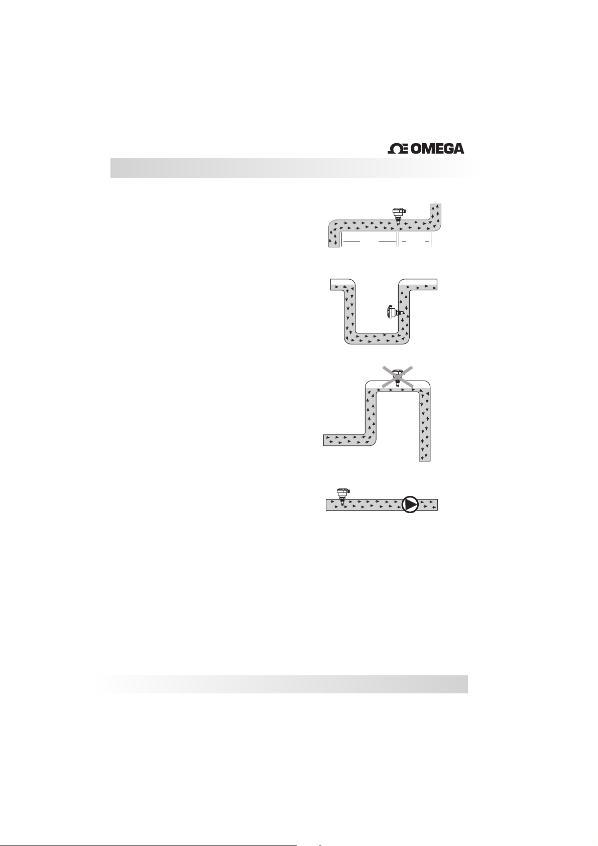
Pre-Installation Checks:
1)
Its recommended that the flow switch is
installed with
bent where the flow enters and 5x times the
diameter of the pipe where the flow exits, enabling
it to havean accurate reading (Fig.1).
Verify that the installation point isn’t near any
connections, valves, elbows or anything similar,
this can cause errors in the reading of the probe
due to turbulencein the pipe.
2) It isimportant that theflow switch isnot installed
at the highest point in the pipe run or in a location
where there is the risk of air accumulating in the
pipe. Keep in mind that the ideal mounting
location is where the pipe is always full. This will
ensure that the switch is always immersed in the
flow. (Fig. 2 correct, fig. 3 incorrect)
3) In pipes that have pressure pumps or retention
valves, we recommend that the probe be installed
before the pump due to the fact that it will have
less turbulence. (Fig.4)
a distance of ½ a meter of the pipe
Fig.1
Fig.2
Fig.3
Fig.4
1/2m
5xØ
4) Confirm that the wire connections are correct
and that the available power supply is compatible
with the FSWunit.
5) Verify that the operating pressure and
temperature of the process corresponds to the
operating p arameters of the FSW unit.
More recommendations and handling instructions
can be foundon page 14.
www.omega.come-mail:[email protected]
Pump
09
Page 10
Installation
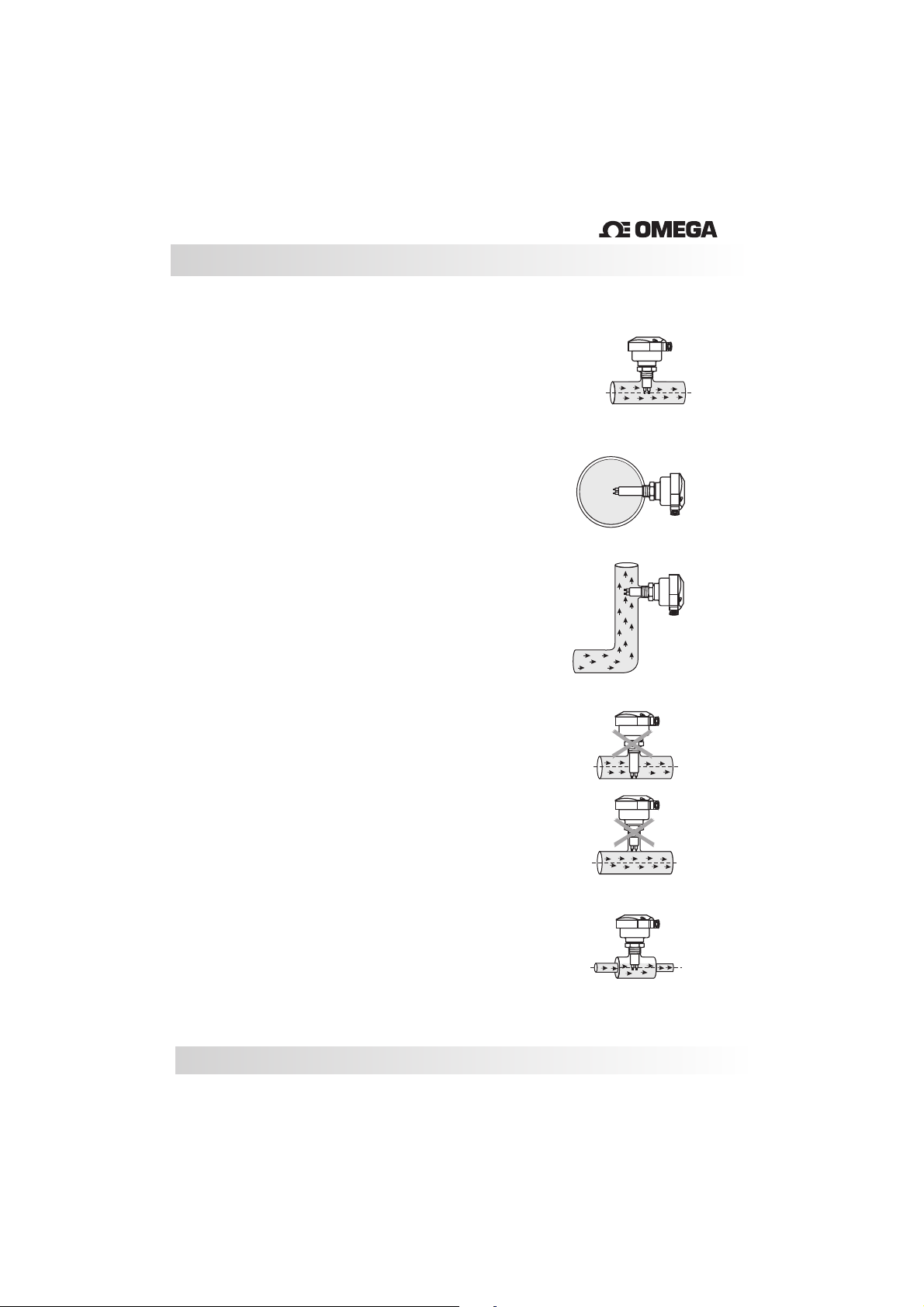
Installation:
The FSW may be installed in a pipe using a
“T”connection (see
the pipe (see fig. 2). The site might need to adapt
the installation so that it conforms with the
following recommendations.
The FSW is not affected by its fixed position so it
may be installed at any angle around the pipe.
However we recommendthat when thepipe is in a
horizontal position theFSW should beinstalled on
the side, as long as the tip of the probe sits within
the middle ofthe pipe
(See Fig. 2).
When the pipeis in a verticalposition, the FSW
should be installedonly when the waterflow is
upward (See Fig.3).
fig. 1) or inserted directly into
Fig.1
FlowSwitchwith
“T” connection
Fig.2
Fig.3
®
Care should betaken when installing the FSWthat
the probe extends to the center of the pipe away
from the internal wall andis fully immersed into the
flow ( Fig. 4 and 5 incorrect, Fig.1 and 2 are
correct).
In pipes with smaller diameters use an adaptor to
enlarge the diameter of the pipe so that the sensor
can be properly installed (See Fig. 6). If the
installation is not correct the FSW’s performance
may be affected.
10
Fig.4
Incorrect
Fig.5
Fig.6
Page 11
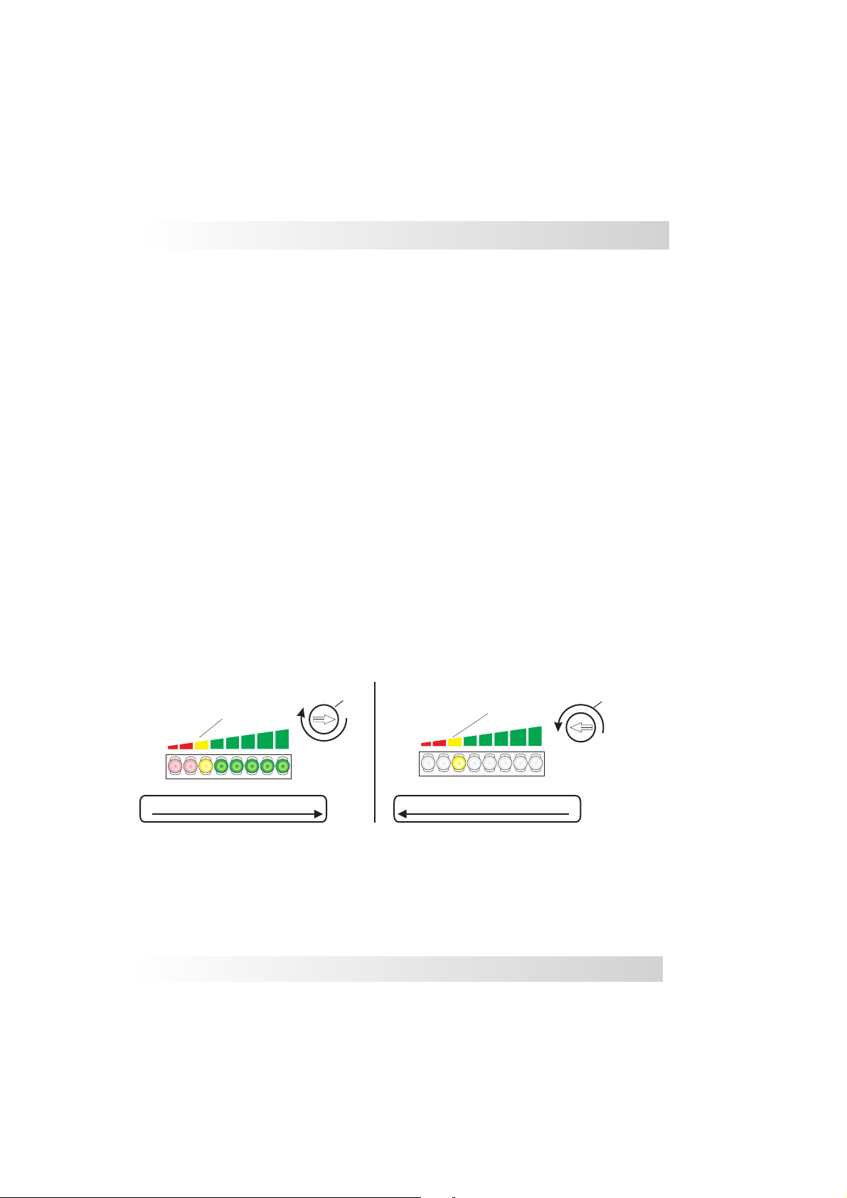
Calibration
T
o Start:
1 - Removethe enclosure lid (Note:the screws are self-retaining)
2
Start the power supply and wait 5 minutes until the FSW is active and has reached a
stable point withinthe medium.
3 - Letthe regular or desiredflow reach its point of normal operation.
Calibration for Flow/ No Flow:
1 - Setthe flow rate atthe normal range of operation.
2 - Turn the potentiometer counter-clockwise until thecentral LED turns red.
3 - With the central LED red, turn the potentiometer clockwise until the central LED
changes to ablinking green state.
4 - Continue to turn the potentiometer clockwise until all green LEDs in the bar graph are
on.
5 - In order to be sure that the adjustment is not at a critical state give the potentiometer
an additional quarterturn clockwise.
Set Point Adjustment:
The flow switch can beadjusted to indicate either increasing flow, or decreasing flow at a
specific set pointwithin 3cm/s to 3m/s.
It is important to determine the specific set point at which the flow switch should activate
or de-activate.
Adjust
SetPoint
0%
BARGRAPH-LightsON
BARGRAPH-LightsON
100%
www.omega.come-mail:[email protected]
0%
SetPoint
Adjust
100%
BARGRAPH-LightsOFF
BARGRAPH-LightsOFF
11
Page 12

Calibration
T
o Activate The Switch OnIncreasing Flow:
1 - Set the flowrate to the desired set point and allow it to stabilize for 2minutes.
2 - Turn the potentiometer counter-clockwise until thecentral LED turns red.
3 - Turn the potentiometer clockwise until thecentral LED changes toa blinking green.
4 - Continue to turn the potentiometer clockwise until the first 2 green LEDs in the bar
graph turn on.
In this mode the FSW will activated on or above the set point. If there is a decrease of
flow, the FSW will de-activate. When the flow rate reaches the set point, the FSW will
activate.
To De-Activate The Switch On Decreasing Flow:
1 - Set the flowrate to the desired set point and allow it to stabilize for 2minutes.
2 - Turn the potentiometer clockwise until thecentral LED is blinkinggreen.
3 - Turn the potentiometer counter-clockwise until thecentral LED turns red.
4 - Continue to turn the potentiometer counter-clockwise until the 2 red LEDs in the bar
graph are off.
In this mode the FSW will de-activate on or below the set point. If there is an increase of
flow the FSW will activate. When the flow rate reaches the set point, the FSW will deactivate.
Detecting level:
1 - Fill the tank until the probe of the FSW is fully submerged. Turn the potentiometer
counter-clockwise until the central LED turns red. With the central LED red, turn the
potentiometer clockwise untilthe central LED changesto a blinking green.
2 - Continueto turn potentiometer clockwiseuntil all green LEDs in the bar graph turn on.
3 - In order to be sure that the adjustment is not at a critical state give the potentiometer
an additional quarterturn clockwise.
12
Page 13
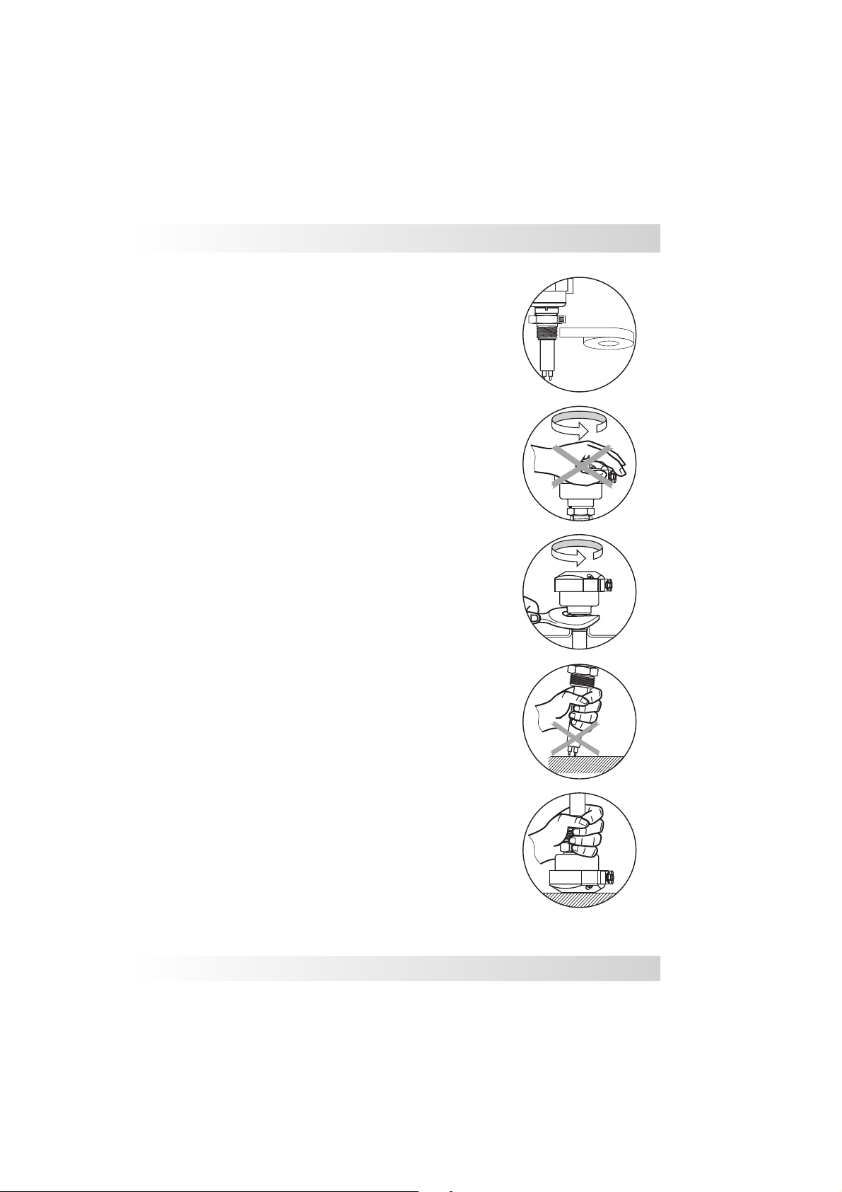
Handling
Sealthethreadwith Teflontapebefore
installation(Fig.1).
Donotturnorhandlebythehousing(Fig.2).
Usethecorrecttoolduringinstallation(Fig.3)
The FSW should not be dropped or suffer any
impact or fall that could damage the electronics or
the thermal tipsof the probe (Fig.4 and 5).
Periodic visual inspection of the FSW is required
to check for corrosion or deposit build-up. If
deposits are found, clean the sensor to ensure
optimum performance.
Care should be taken when handling and installing
probes
with coated rods to avoid scratching them.
Scratching the coating could interfere with the
probe performance.
When cleaning the rod use a soft brush or any
other similar object.
Fig.1
Fig.2
Fig.3
Fig.4
www.omega.come-mail:[email protected]
Fig.5
13
Page 14
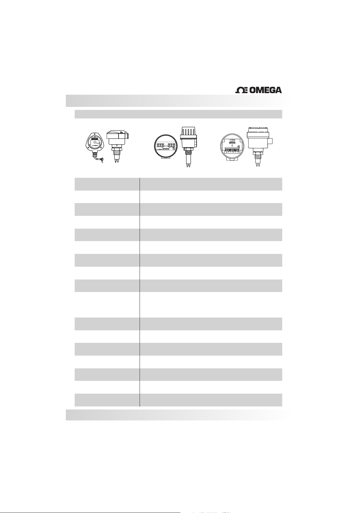
TechnicalSpecifications
®
FSW6000
Adjust
NylonHousing
Application
OperatingV
oltage
CurrentConsumption
Output
SetPointRange
Accuracy
Repeatability
Response Time
Gradient Temperature
FlowRateIndication
1 2 3 4 5 6
_
+
Adjust
1 234
+
100%0
Flow
5 6
8
7 9
-
AluminumHousingAluminumHousing
Flowforliquidsandgaslevelforliquidsonly
85-240Vac(50/60hz)or125Vdc
+/-100mA
Relay(SPDT)5A -250VacforNylonandSmall AluminumHousing
(2SPDT Large AluminumHousing)
Liquid:3cm/sto3m/s-Gas:5cm/sto5m/s
+/-10%
+/-1%setpoint
1to10s
15ºC/min
Redled-flowisbelowsetpoint
Yellowled-flowisatsetpoint
Greenled-flowisabovesetpoint
EnclosureMaterial
ElectricalConnection
ProcessConnection
WettedMaterial
Operating Temperature
MaxPressure
ClassProtection
14
Glassfillednylon(option- Aluminum)
Cableglandw/2000mmcable,M12connectoror½” NPT
½” to11/2” BSP orNPT,adjustable,sanitaryorflangedconnections
316StainlessSteel
14to176ºF(-10to80ºC)sanitaryoptionto248ºF(120ºC)
1450PSI(100Bar)/4500PSI(300Bar)uponrequest
IP 65
Page 15
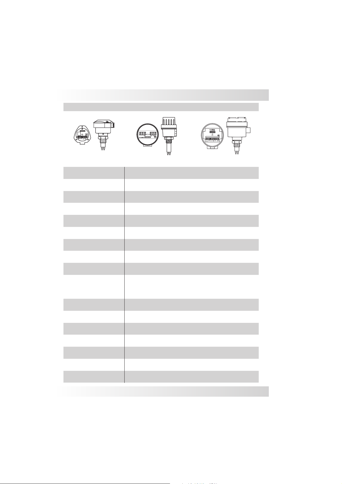
FSW7000
TechnicalSpecifications
Adjust
_
+
NylonHousing
Application
OperatingV
oltage
CurrentConsumption
Output
SetPointRange
Accuracy
Repeatability
Response Time
Gradient Temperature
FlowRateIndication
1 2 3 4 5 6
_
+
Adjust
Flowforliquidsandgaslevelforliquidsonly
Relay(SPDT)5A
Liquid:3cm/sto3m/s-Gas:5cm/sto5m/s
100%0
Flow
5 6
8
1 234
7 9
+
-
AluminumHousingAluminumHousing
24Vdc(+/-10%)
+/-100mA
-250VacforNylonandSmall AluminumHousing
(2SPDT Large AluminumHousing)
+/-10%
+/-1%setpoint
1to10s
15ºC/min
Redled-flowisbelowsetpoint
Yellowled-flowisatsetpoint
Greenled-flowisabovesetpoint
EnclosureMaterial
ElectricalConnection
ProcessConnection
Cablegland-1/2” NPT conduitentryorM12connector
½” to11/2” BSP orNPT,adjustable,sanitaryorflangedconnections
WettedMaterial
Operating Temperature
MaxPressure
14to176ºF(-10to80ºC)sanitaryoptionto248ºF(120ºC)
1450PSI(100Bar)/4500PSI(300Bar)uponrequest
ClassProtection
www.omega.come-mail:[email protected]
Glassfillednylon(option- Aluminum)
316StainlessSteel
IP 65
15
Page 16
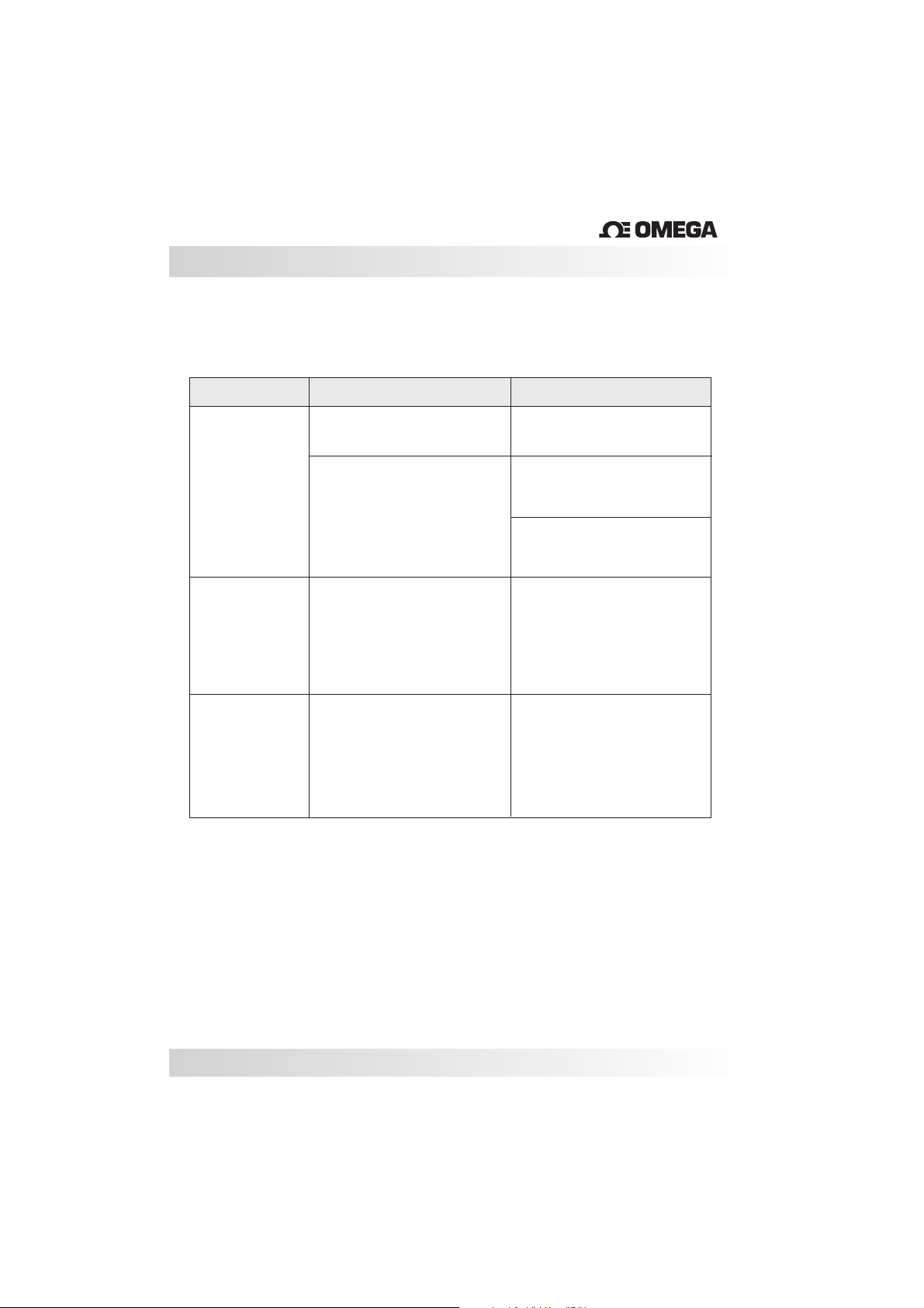
TroubleShooting
®
Fault
Relaydoesnot
changestate.
Flowswitch
turnsonor
of
fsuddenly
Relayremains
closed
Cause
LEDoff,nopower
LEDdoesn’tchangecolor
Radiofrequency
interference
Sensorispotentialy
defective
Solution
Checkpowersupply
Check theinstallation
(insertion length)
Verify thecalibration
Usearmoredcable
andshieldedhousing
ContactOmegaoryour
localrepresentativefor
furtherinstruction
16
Page 17
Page 18
M-3993/1014
 Loading...