

Page 1
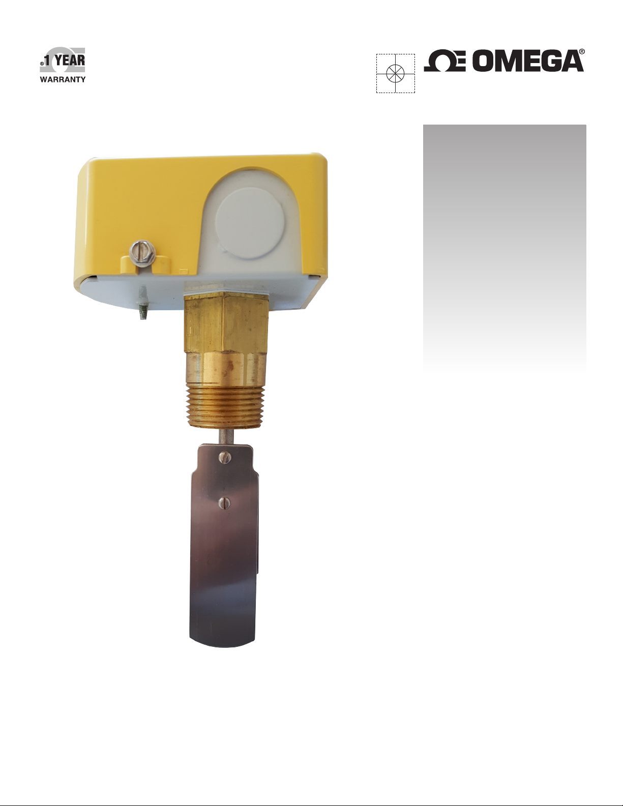
User’s Guide
Shop online at
omega.com
e-mail: [email protected]
For latest product manuals:
www.omegamanual.info
®
FSW-160
Fluid Flow Switches
Page 2

omega.com [email protected]
Servicing North America:
U.S.A.: Omega Engineering, Inc., One Omega Drive, P.O. Box 4047
Stamford, CT 06907-0047 USA
Toll-Free: 1-800-826-6342 (USA & Canada only)
Customer Service: 1-800-622-2378 (USA & Canada only)
Engineering Service: 1-800-872-9436 (USA & Canada only)
Tel: (203) 359-1660 Fax: (203) 359-7700
e-mail: [email protected]
For Other Locations Visit omega.com/worldwide
The information contained in this document is believed to be correct, but OMEGA accepts no liability for any errors it contains, and reserves
the right to alter specifications without notice.
WARNING: These products are not designed for use in, and should not be used for, human applications.
Page 3
MODEL FSW-160
INSTALLATION INSTRUCTION SHEET
Omega Model FSW-160 fluid flow switch is intended for use in flow lines with fluids not harmful
to brass, stainless steel, and EPDM. The switch is used to signal, start, or stop electrically operated
equipment when flow or no-flow conditions occur.
This device is designed for use only as an operating control. Where an operating control failure would
result in personal injury and/or loss of property, it is the responsibility of the installer to add devices
(safety, limit controls), or systems (alarm, supervisory systems) that protect against or that warn of,
control failure.
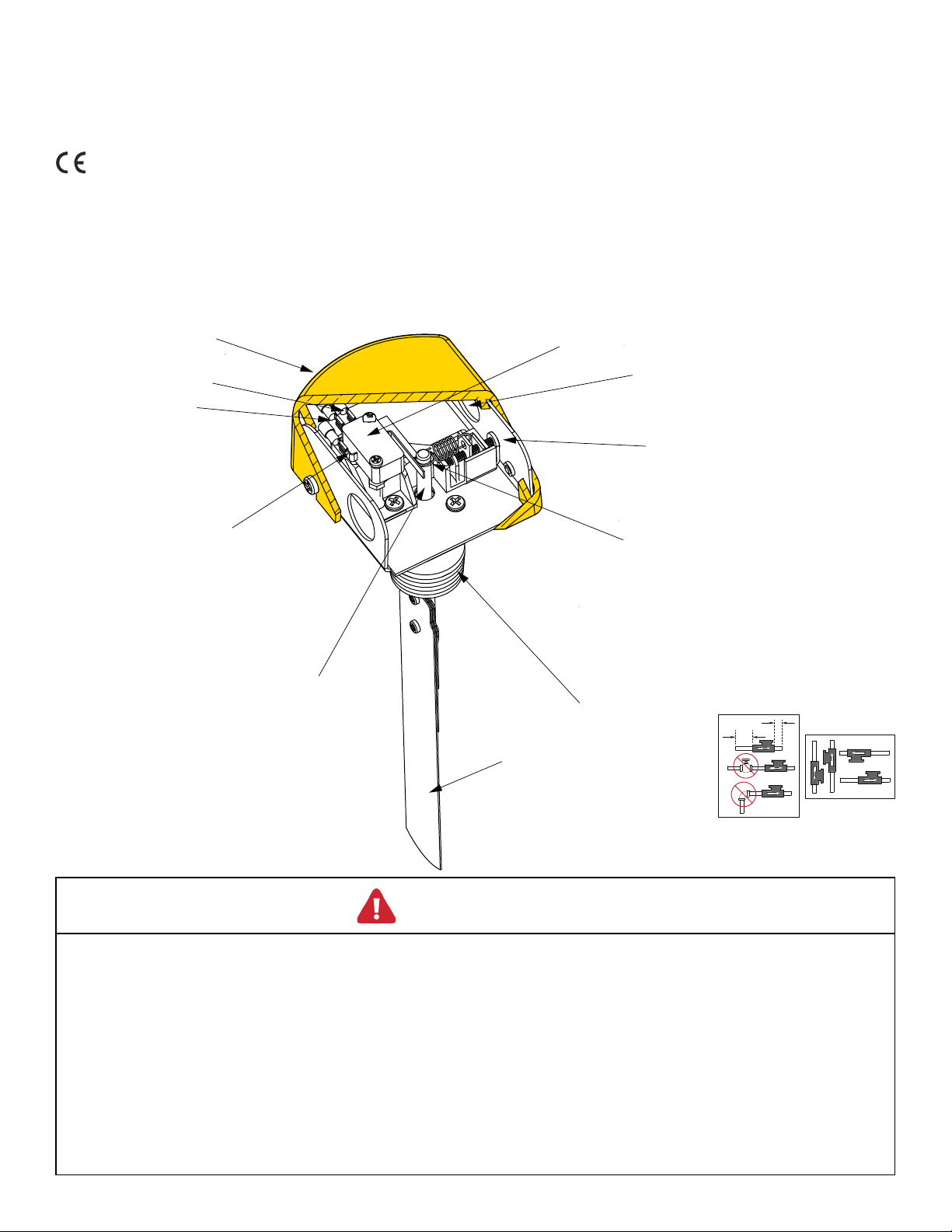
COVER
NORMALLY CLOSED
NORMALLY OPEN
15 AMP - SPDT MICROSWITCH
1/2"
CONDUIT CONNECTION
ADJUSTING SCREW
COMMON
TENSION SPRING
FIGURE 1. PRODUCT
DIAGRAM
FEED THRU SHAFT ASSY
FLOW SWITCH BODY
5D
STAINLESS STEEL PADDLES (4)
WARNING
• Before using product, read and understand instructions.
• Please save these instructions for future use.
• All work must be performed by qualified personnel trained in the proper applications,
installation, and maintenance of plumbing and electrical equipment in accordance with all
applicable codes and ordinances.
2D
TURBULENT
FLOW REDUCTION
MOUNT IN
ANY POSITION
• To prevent electrocution DO NOT TOUCH the switch terminals when electrical power is
connected to the flow switch.
• Make sure flow switch cover is secured before turning on electric power.
P. 3
Page 4
MODEL FSW-160
INSTALLATION INSTRUCTION SHEET
SPECIFICATIONS
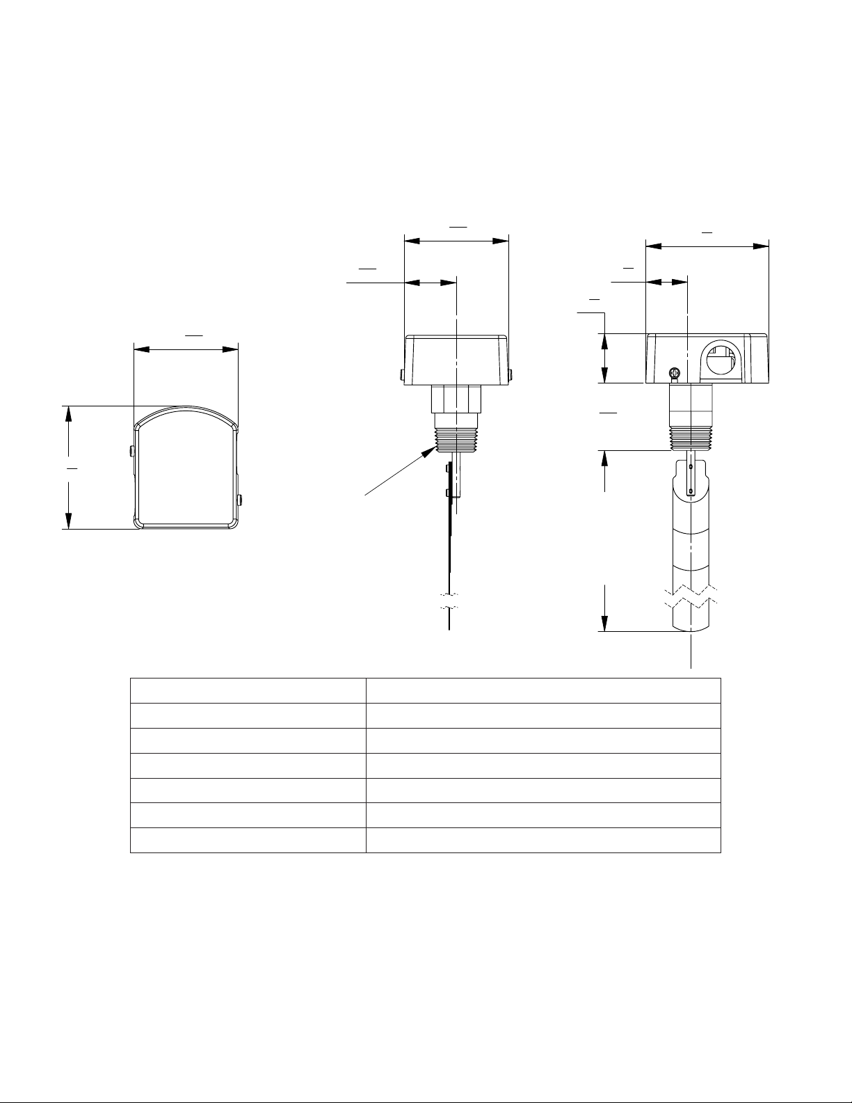
FIGURE 2. INSTALLATION DIMENSIONS
3
3
16
3
3
4
PLAN VIEW
1
1" NPT
19
32
3
3
16
GIVES LENGTHS
SIDE VIEW
1
1
4
1
1
2
1
2
16
INCLUDED
PADDLE SET
OF:
1 1/2, 2 1/2
3 5/8, 7 1/4
3
3
4
FRONT VIEW
Liquid Temperature Range 32˚ - 250˚F (0˚ - 121˚C)
Ambient Temperature Range 32˚ - 150˚F (0˚ - 66˚C)
Maximum Service Pressure 250 psi
Electrical Enclosure Rating NEMA Type 1 (Not for use in hazardous locations.)
Process Connection 1” NPT
Conduit One opening for ½” conduit
Usage 1” Pipe and Larger
ELECTRICAL RATING
Single-Pole-Double-Throw (SPDT)
Contact Rating: 15A, ½ hp; 125, 250, 277VAC
½A, 125VDC; ¼A, 250VDC
P. 4
Page 5
MODEL FSW-160
1½” PIPE
2” PIPE
2½” PIPE
3” PIPE
4” PIPE
5” PIPE
6” PIPE
7” PIPE
1¼” PIPE
0
1.30
1.60
1.85
2.30
2.85
3.40
4.50
6.50
7. 0 0
5.50
INSTALLATION INSTRUCTION SHEET
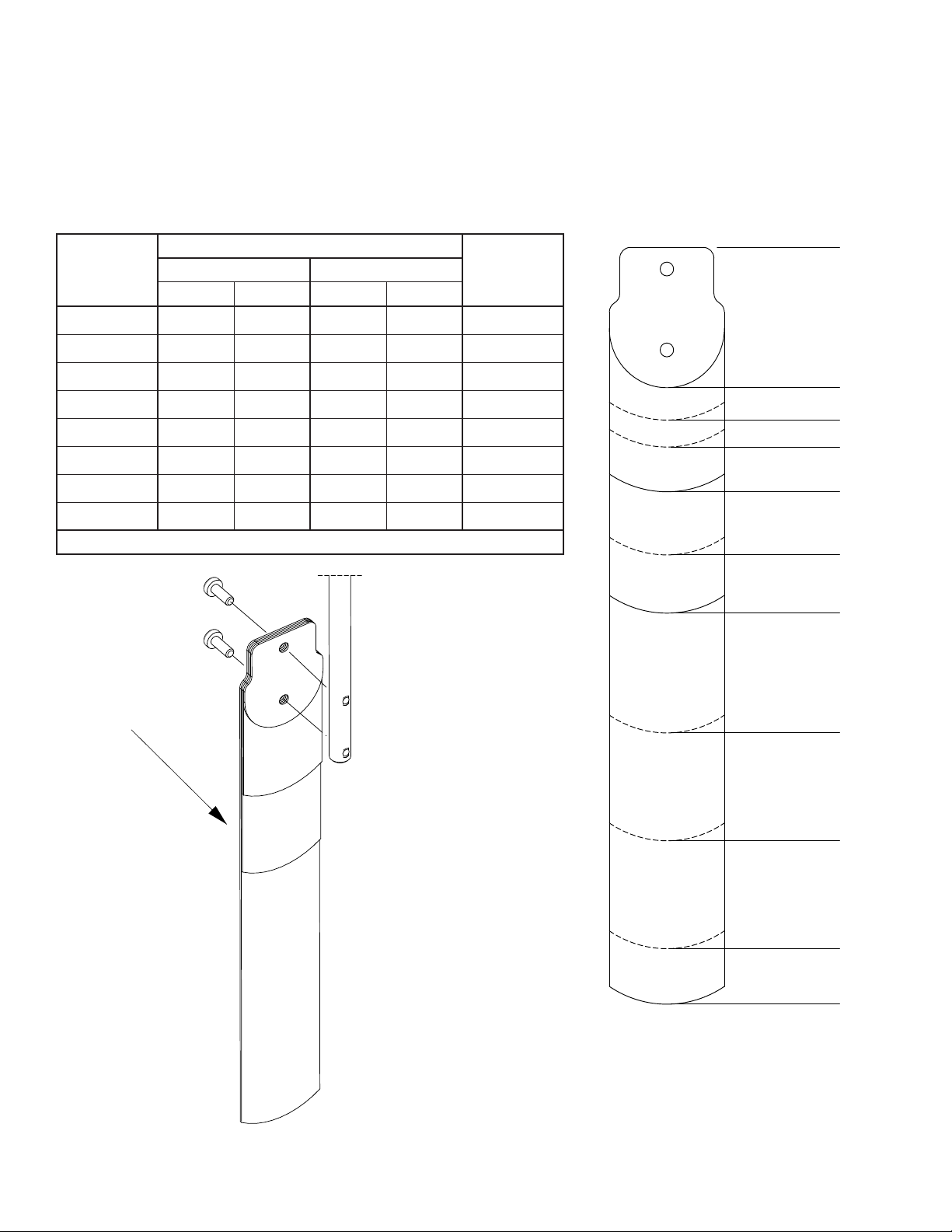
FIGURE 3. FLOW RANGE TABLE FIGURE 4. PADDLE SIZES
Switchpoint Range (GPM)
Pipe Size
NPT
1” 4 2 8 7 1.30”
1½” 7 5 13 11 1.85”
2” 12 7 27 26 2.30”
2½” 18 12 35 32 2.83”
3” 27 19 52 49 3.40”
Min. Adjust. Max. Adjust.
ON OFF ON OFF
Paddle Size
(inches)
4” 63 50 123 120 4.50”
5” 125 100 238 232 5.50”
6” 190 158 350 338 6.50”
Consult the factory for larger pipes and additional switch points.
DIRECTION
OF FLOW
FIGURE 5.
MULTIPLE PADDLE
CONFIGURATION
P. 5
Page 6
MODEL FSW-160
INSTALLATION INSTRUCTION SHEET
INSTALLATION
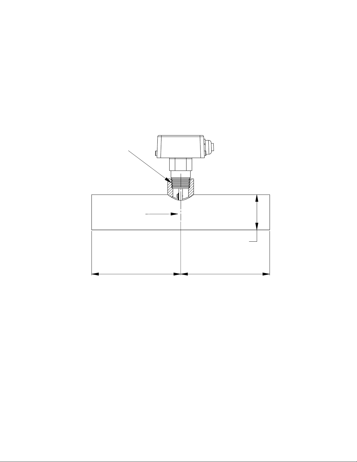
The Model FSW-160 should be mounted on the top of a horizontal section of pipe. If it is mounted in
a vertical pipe, the switch points will deviate from those published. If the flow is DOWNWARD, switch
points will be LOWER than published. If flow is UPWARD, switch points will be HIGHER than published.
FIGURE 6. FSW-160 IN
PIPE
1" PIPE
CONNECTION
FLUID FLOW
D
5 x D
MINIMUM
D= PIPE DIAMETER
The flow switch should be located in a straight run of at least 5 pipe diameters.
1. Determine the proper paddle length from the chart next to the “Flow Range” Table [FIGURE 3]. For
intermediate sizes, trim the next largest paddle to the correct length. The paddle must not touch the
inside of the pipe. If more than one paddle is being installed, stack one on top of the other with the
larger ones first in line with the flow. [FIGURE 5.]
2. Use a reducing tee for pipe sizes larger than 1” to provide adequate paddle length in the liquid
flow. A weldolet or half coupling may also be used. If a reducing tee is not available, use a bushing
to reduce the tee outlet to 1” pipe thread.
5 X D
MINIMUM
3. Be sure the flow switch is mounted such that the flow direction is perpendicular to the paddle and
that it activates the flow switch when there is flow and de-activates at rest when there is no flow.
CAUTION: DO NOT TIGHTEN BY GRASPING THE SWITCH ENCLOSURE. USE THE HEX FLATS AND
WRENCH.
P. 6
Page 7
MODEL FSW-160
LOAD
INSTALLATION INSTRUCTION SHEET
ELECTRICAL WIRING
WARNING
• To prevent electrical shock, turn off the electrical
power before making electrical connections.
• To prevent electrocution, do not touch the terminals
when electrical power is connected to the flow
switch.
FIGURE 7.
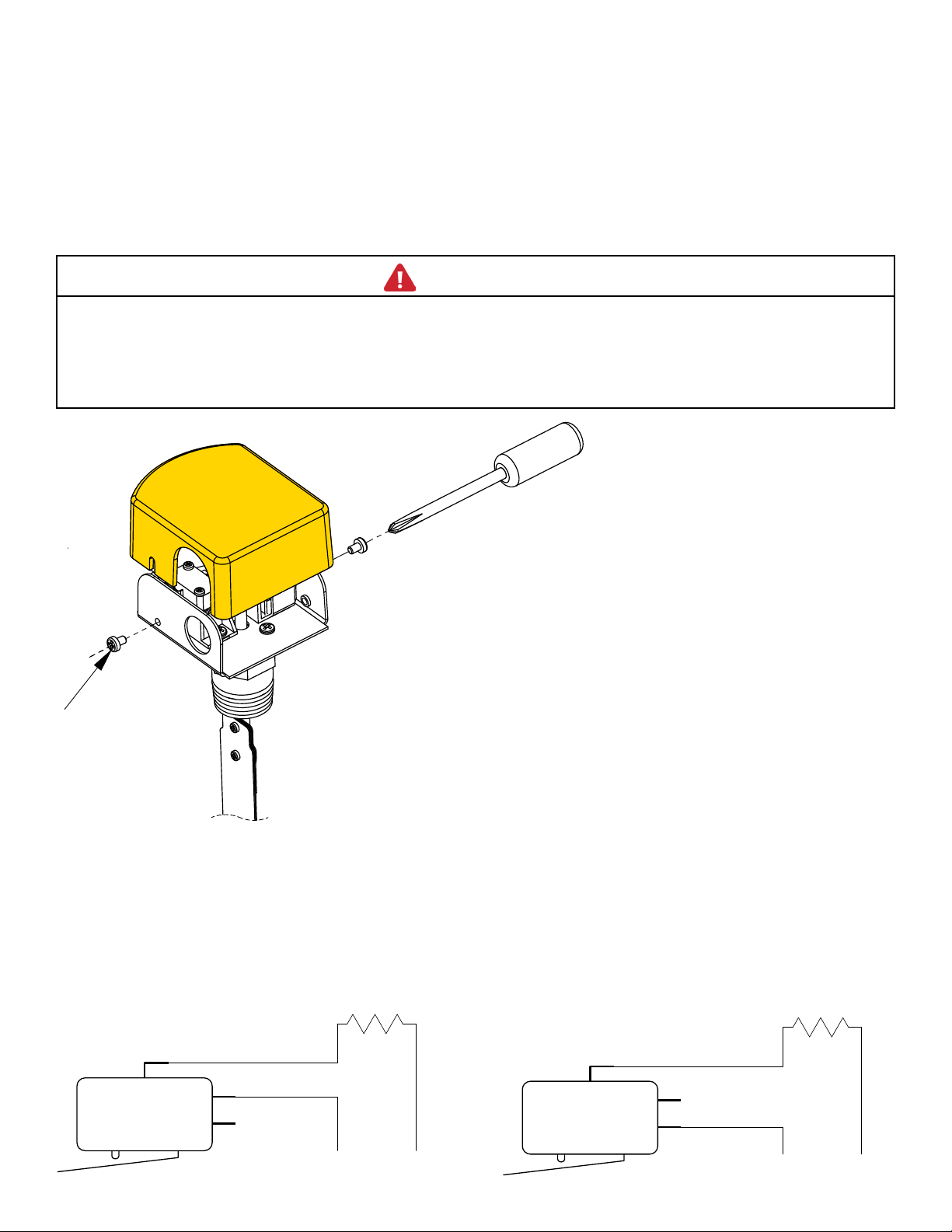
1. Using a Phillips screwdriver,
remove the two (2) cover
LOOSEN OR
screws and remove the cover.
REMOVE
SCREWS TO
REMOVE
COVER
2. Connect electrical conduit
connector to the flow switch
enclosure. Follow accepted
electrical practices when
installing fittings and making
connections. Refer to, and
• To prevent an electrical fire or equipment damage,
use properly temperature-rated supply wire for the
anticipated temperature.
• Make all electrical connections in accordance with
the National Electrical Code and local regulations.
follow, local codes and
standards when selecting the
types of electrical fittings and
conduit to connect to flow
switch.
3. Determine which switch action
is required for the flow switch.
4. Using a scissor-style crimping
tool (3M TH-450 or equivalent),
crimp 14 gage wire to the
female flag disconnect terminals
(3M 752-187) included with
the switch.
*Note: Use copper wire only
5. Attach ground wire to green
grounding screw on flow switch
base.
Power applied to load when flow is
GREATER than set point, interrupted when
flow is LESS than set point (normally open).
FIGURE 8.
HOT
COM
NO
NC
LINE
Power applied to load when flow is LESS
than set point, interrupted when flow is
GREATER than set point (normally closed).
FIGURE 9.
COM
HOT
NO
NC
LOAD
LINE
P. 7
Page 8
MODEL FSW-160
INSTALLATION INSTRUCTION SHEET
SWITCH POINT ADJUSTMENT
1. TURN OFF POWER.
2. Remove cover.
3. Adjust fluid flow in system to desired
rate WITHOUT regard to FSW-160
switch point setting.
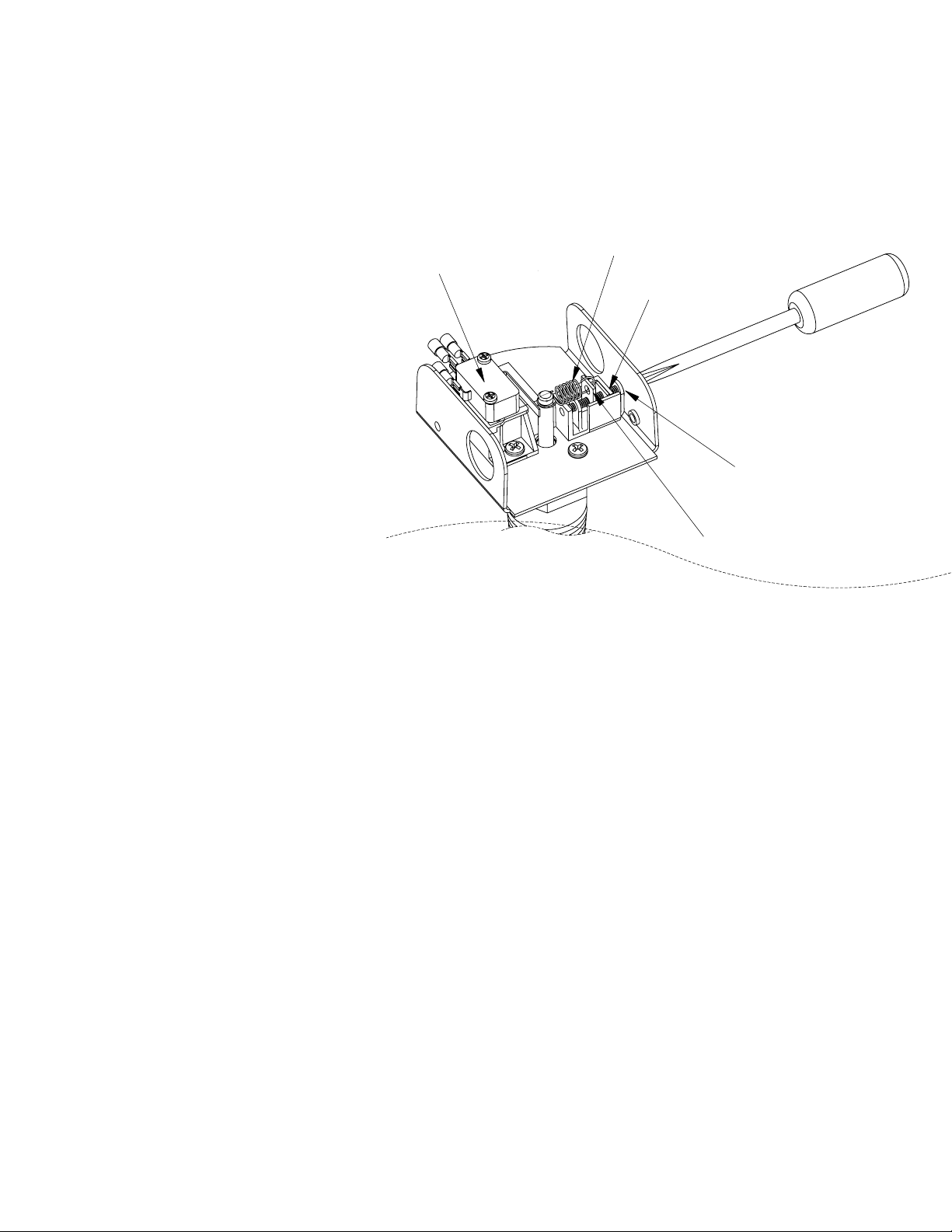
4. The switch point adjusting mechanism
consists of an adjusting screw, a “U”
shaped nut, and a helical spring.
CLOCKWISE rotation of the adjusting screw
changes the microswitch actuation point
toward HIGHER flow rates.
NOTES: All FSW-160 units are factory set
at the lower end of the flow range, e.g.
the adjusting screw is set at the low flow
counter-clockwise position.
MICROSWITCH
FIGURE 10.
SPRING POSITION
WHEN DELIVERED
LEADSCREW
BEST ADJUSTMENT POINT
(CENTERED)
ADJUST LEADSCREW
The lead screw nut locks the adjusting screw
in position, maintaining the flow switch set
point under all environmental conditions.
5. Starting with the nut in low-flow position (tension
spring relaxed), turn the adjusting screw in
a clockwise direction until the microswitch is
actuated, while maintaining the desired fluid flow
rate in the system. Turn the adjusting screw TWO
(2) additional turns in the clockwise direction
and then slowly back off in a counter-clockwise
direction, until the microswitch is de-actuated.
The FSW-160 flow switch is now set at maximum
sensitivity for detecting small flow changes.
6. When set at maximum sensitivity (100% point) as
described above, flow turbulence may cause rapid
on/off switching (dithering) of the microswitch
contacts, resulting in reduced switch contact
TESTING
Place cover on flow switch and turn on power. Observe whether the flow switch is being activated by the flow.
Turn off fluid flow to determine if the device is operating as required.
life and “noise” in the electrical circuit. This is
eliminated by turning the adjusting screw in a
counter-clockwise direction.
7. Microswitch actuation point may be monitored
during the adjustment procedure detail in steps 5
and 6 by an audible click, with an ohmmeter, or
with other continuity tester before connecting line
power to the microswitch.
8. If the system flow rate is changed, the FSW-160
can be adjusted to monitor the new flow rate by
turning the adjusting screw in a counter-clockwise
direction to the minimum flow position and then
proceeding as in 5 and 6 above.
9. Place cover on the flow switch and turn on power.
10. Test the operation of the flow switch after each
adjustment.
Repeat initiating and turning off fluid flow several times. If operating as required, put system into service. If not
operating as required, flow switch may need to be adjusted.
P. 8
Page 9

WARRANTY/DISCLAIMER
OMEGA ENGINEERING, INC. warrants this unit to be free of defects in materials and workmanship for a
period of 13 months from date of purchase. OMEGA’s WARRANTY adds an additional one (1) month
grace period to the normal one (1) year product warranty to cover handling and shipping time. This
ensures that OMEGA’s customers receive maximum coverage on each product.
If the unit malfunctions, it must be returned to the factory for evaluation. OMEGA’s Customer Service
Department will issue an Authorized Return (AR) number immediately upon phone or written request.
Upon examination by OMEGA, if the unit is found to be defective, it will be repaired or replaced at no
charge. OMEGA’s WARRANTY does not apply to defects resulting from any action of the purchaser,
including but not limited to mishandling, improper interfacing, operation outside of design limits,
improper repair, or unauthorized modification. This WARRANTY is VOID if the unit shows evidence of
having been tampered with or shows evidence of having been damaged as a result of excessive corrosion;
or current, heat, moisture or vibration; improper specification; misapplication; misuse or other operating
conditions outside of OMEGA’s control. Components in which wear is not warranted, include but are not
limited to contact points, fuses, and triacs.
OMEGA is pleased to offer suggestions on the use of its various products. However,
OMEGA neither assumes responsibility for any omissions or errors nor assumes liability for
any damages that result from the use of its products in accordance with information provided
by OMEGA, either verbal or written. OMEGA warrants only that the parts manufactured by the
company will be as specified and free of defects. OMEGA MAKES NO OTHER WARRANTIES OR
REPRESENTATIONS OF ANY KIND WHATSOEVER, EXPRESSED OR IMPLIED, EXCEPT THAT OF
TITLE, AND ALL IMPLIED WARRANTIES INCLUDING ANY WARRANTY OF MERCHANTABILITY
AND FITNESS FOR A PARTICULAR PURPOSE ARE HEREBY DISCLAIMED. LIMITATION OF
LIABILITY: The remedies of purchaser set forth herein are exclusive, and the total liability of
OMEGA with respect to this order, whether based on contract, warranty, negligence,
indemnification, strict liability or otherwise, shall not exceed the purchase price of the
component upon which liability is based. In no event shall OMEGA be liable for
consequential, incidental or special damages.
CONDITIONS: Equipment sold by OMEGA is not intended to be used, nor shall it be used: (1) as a “Basic
Component” under 10 CFR 21 (NRC), used in or with any nuclear installation or activity; or (2) in medical
applications or used on humans. Should any Product(s) be used in or with any nuclear installation or
activity, medical application, used on humans, or misused in any way, OMEGA assumes no responsibility
as set forth in our basic WARRANTY/DISCLAIMER language, and, additionally, purchaser will indemnify
OMEGA and hold OMEGA harmless from any liability or damage whatsoever arising out of the use of the
Product(s) in such a manner.
RETURN REQUESTS/INQUIRIES
Direct all warranty and repair requests/inquiries to the OMEGA Customer Service Department.
BEFORE RETURNING ANY PRODUCT(S) TO OMEGA, PURCHASER MUST OBTAIN AN AUTHORIZED
RETURN (AR) NUMBER FROM OMEGA’S CUSTOMER SERVICE DEPARTMENT (IN ORDER TO AVOID
PROCESSING DELAYS). The assigned AR number should then be marked on the outside of the return
package and on any correspondence.
The purchaser is responsible for shipping charges, freight, insurance and proper packaging to prevent
breakage in transit.
FOR WARRANTY RETURNS, please have the
following information available BEFORE
contacting OMEGA:
1. Purchase Order number under which the product
was PURCHASED,
2. Model and serial number of the product under
warranty, and
3. Repair instructions and/or specific problems
relative to the product.
OMEGA’s policy is to make running changes, not model changes, whenever an improvement is possible. This affords
our customers the latest in technology and engineering.
OMEGA is a registered trademark of OMEGA ENGINEERING, INC.
© Copyright 2013 OMEGA ENGINEERING, INC. All rights reserved. This document may not be copied, photocopied,
reproduced, translated, or reduced to any electronic medium or machine-readable form, in whole or in part, without the
prior written consent of OMEGA ENGINEERING, INC.
FOR NON-WARRANTY REPAIRS,
for current repair charges. Have the following
information available BEFORE contacting OMEGA:
1. Purchase Order number to cover the COST
of the repair,
2. Model and serial number of the product, and
3. Repair instructions and/or specific problems
relative to the product.
consult OMEGA
Page 10

Where Do I Find Everything I Need for
Process Measurement and Control?
OMEGA…Of Course!
Shop online at omega.com
TEMPERATURE
MU
Thermocouple, RTD & Thermistor Probes, Connectors, Panels & Assemblies
MU
Wire: Thermocouple, RTD & Thermistor
MU
Calibrators & Ice Point References
MU
Recorders, Controllers & Process Monitors
MU
Infrared Pyrometers
PRESSURE, STRAIN AND FORCE
MU
Transducers & Strain Gages
MU
Load Cells & Pressure Gages
MU
Displacement Transducers
MU
Instrumentation & Accessories
FLOW/LEVEL
MU
Rotameters, Gas Mass Flowmeters & Flow Computers
MU
Air Velocity Indicators
MU
Turbine/Paddlewheel Systems
MU
Totalizers & Batch Controllers
SM
pH/CONDUCTIVITY
MU
pH Electrodes, Testers & Accessories
MU
Benchtop/Laboratory Meters
MU
Controllers, Calibrators, Simulators & Pumps
MU
Industrial pH & Conductivity Equipment
DATA ACQUISITION
MU
Data Acquisition & Engineering Software
MU
Communications-Based Acquisition Systems
MU
Plug-in Cards for Apple, IBM & Compatibles
MU
Data Logging Systems
MU
Recorders, Printers & Plotters
HEATERS
MU
Heating Cable
MU
Cartridge & Strip Heaters
MU
Immersion & Band Heaters
MU
Flexible Heaters
MU
Laboratory Heaters
ENVIRONMENTAL
MONITORING AND CONTROL
MU
Metering & Control Instrumentation
MU
Refractometers
MU
Pumps & Tubing
MU
Air, Soil & Water Monitors
MU
Industrial Water & Wastewater Treatment
MU
pH, Conductivity & Dissolved Oxygen Instruments
M-5540/1015
 Loading...