

Page 1

"Protect Yourself And Your Investment"
OO
WNER'S MANUWNER'S MANU
O
WNER'S MANU
OO
WNER'S MANUWNER'S MANU
&&
&
&&
WIRING INSTRWIRING INSTR
WIRING INSTR
WIRING INSTRWIRING INSTR
MODEL:MODEL:
MODEL:
MODEL:MODEL:
COPYRIGHT: OMEGA RESEARCH & DEVELOPMENT 1997
UCTIONSUCTIONS
UCTIONS
UCTIONSUCTIONS
411 411
411
411 411
ALAL
AL
ALAL
AA
TVTV
A
TV
AA
TVTV
Table Of Contents
Arming The Alarm ............................................................................................................................................ 3
Disarming The Alarm ....................................................................................................................................... 3
Triggering The Alarm .................................................................................................................................... 3- 4
Remote Panic Operation ................................................................................................................................... 4
Automatic Transmitter Verification
Code JumpingTM................................................................................................................................................ 6
Using The Transmitter To Turn On And Off The Confirmation Chirps ....................................................... 5-6
Using The Transmitter To Adjust The Dual Zone Shock Sensor ..................................................................... 6
Current Sensing (Green Wire Loop) ................................................................................................................. 7
Three Minute Current Sensing Delay (White Wire Loop) ................................................................................ 7
Prewarn Feature ............................................................................................................................................. 7-8
Self Diagnosis ................................................................................................................................................... 8
Mounting The Main Control/Siren Unit ........................................................................................................... 9
Wiring Diagram Overview.............................................................................................................................. 10
Short Black Ground Wire................................................................................................................................ 11
Red Constant 12 Volt Positive Wire .......................................................................................................... 11-12
Long Black Antenna Wire .............................................................................................................................. 12
Blue Negative Instant Trigger Wire ........................................................................................................... 12-14
Orange Grounded Output While Armed Wire ........................................................................................... 15-16
Diagram For Starter Disable Diagram ............................................................................................................ 1 6
White Flashing Parking Light Output Wire ............................................................................................... 17-19
Pink LED Status Light Wire ...................................................................................................................... 20-21
Programming The Alarm Control Module To The Transmitter ................................................................ 22-23
Operating A Second Vehicle's Alarm ............................................................................................................. 23
Sometimes You Have To Transmit Close To The Vehicle.............................................................................23
Limited Lifetime Warranty .............................................................................................................. Back Cover
TM
........................................................................................................... 4-5
Operating Instructions
Arming The Alarm:
The Alarm Can Be Armed From Transmitter At Any Time. To arm the alarm system,
after you exit the vehicle, close all of the doors and press the large transmitter button
once. The alarm will respond with one siren chirp, the parking lights will flash once, and
the LED Status Light will flash fast. If an optional doorlock interface (model DM-1) was
installed, the doors will also lock. Five seconds after the arming confirmation chirp, the
LED Status Light will flash slow, confirming that the alarm is fully armed.
Disarming The Alarm:
Whenever the alarm is in an armed state the LED Status Light will be flashing slow.
To disarm the alarm, press the large transmitter button once again. The alarm will respond
with two siren chirps, the parking lights will flash twice. If the alarm was triggered while
you were away, the disarming confirmation will change to four chirps, the parking lights
will flash four times. If the optional DM-1 doorlock interface was installed, the doors will
also unlock upon disarming.
Triggering The Alarm:
Once armed, any entry or shock to the vehicle will instantly trigger the alarm. Once
triggered, the siren will sound and the exterior lights will flash for 60 seconds, unless you
disarm the alarm sooner with the transmitter. If all protected entries are secure at the end
of 60 seconds, the alarm will stop and automatically rearm itself. If any further entry
Page - 3
Continued Next Page
attempt is made, the alarm will trigger again and repeat the process. During the 60 sec- ond
triggered cycle, you may use the transmitter to disarm the alarm, rather than waiting for it
to reset itself. Remember, once the alarm triggers, the disarming confirmation is four
chirps and four parking light flashes.
Remote Panic Operation:
In the event of attack or assault, or any time you feel threatened or in need of assistance,
you can use the transmitter to trigger the alarm as a possible means of getting help or
diverting the attacker's attention. Pressing and holding the large transmitter button for 2
seconds will trigger the alarm, which will sound the siren and flash the parking lights for
60 seconds. At 60 seconds, the alarm will automatically reset itself to the armed mode, or,
you may use the transmitter to turn off this feature, which will also disarm the alarm. The
panic feature may be used at any time - while the alarm is armed or disarmed, and regardless
of whether the ignition switch is turned on or off. If desired, a single pole, double throw
switch may be added to the alarm's Red constant power wire as a means of disarming the
alarm system if the transmitter is lost, damaged, or if its battery becomes exhausted. This
optional switch must be mounted in a concealed, but accessible location.
Automatic Transmitter VerificationTM:
For a period of 20 seconds after the alarm is disarmed by the transmitter, the LED Status
Indicator will flash to indicate the number of transmitters programmed to operate your
security system. For example: two flashes and a pause indicate that only two transmitters
are coded to operate your system. In the event the LED Status Indicator flashes a total of
stored transmitter codes different from the number of transmitters you have
Page - 4
Page 2

programmed to operate your system, you can now erase all codes and immediately
reprogram your transmitters. This patented feature alerts you if a thief has entered an
unauthorized transmitter code into your security system for the purpose of breaking into or
stealing your car or its contents.
Code JumpingTM:
Each time a code is broadcast to the security system, the transmitter and security system
will advance to another code to use for the next transmission. This prevents "code grabber"
units from copying the transmitter to operate the security system. It would take about 60
years of normal use before the transmitter would send the same code again. Please note that
pressing the arm / disarm button on the transmitter at any time while out of range of the
security system can advance the code beyond the range of recognition. If this occurs, simply
press the arm / disarm button a few times to synchronize the codes between the transmitter
and the security system.
Programmable Features
Using The Transmitter To Turn On And Off The Confirmation Chirps:
The alarm system comes with the siren confirmation chirps turned on. The transmitter
may be used to turn off the confirmation chirps, which will allow for silent arming and
disarming. Within 5 seconds after disarming the alarm, press and hold the small transmitter
button until the alarm responds with a siren burst. A two second siren burst only
Page - 5
Continued Next Page
means that the alarm will arm and disarm without siren confirmation chirps. A two
second siren burst followed by a chirp means that the alarm will arm and disarm
with confirmation chirps: one chirp upon arming, two chirps upon disarming. If the
alarm triggered, and then reset itself while you were away, four chirps will be heard
upon disarming.
Using The Transmitter To Adjust The Dual Zone Shock Sensor:
When the alarm system is armed by pressing the large transmitter button, you
will have a 5 second period in which you can adjust the built-in shock sensor. When
the large button is pressed, you will hear one siren chirp. At this point, if you press
the small button within 5 seconds, you will hear one of 4 sets of siren bursts and
chirps, which will indicate at which level of sensitivity that the shock sensor is. At
this time you can change the level of sensitivity by pressing the small transmitter
button. Each time that you press the small transmitter button you will change
the level of the shock sensor's sensitivity. Stop pressing the small transmitter button
when the desired sensitivity level is reached. Five seconds later, when the alarm
becomes fully armed, the shock sensor's sensitivity level will be the last one heard.
Levels Of Shock Sensor Sensitivity :
1) One audible tone = Shock sensor is turned off.
2) One audible tone and one chirp = Low shock sensor sensitivity.
3) One audible tone and two siren chirps = Medium shock sensor
sensitivity.
4) One audible tone and three siren chirps = High shock sensor sensitivity.
Page - 6
Current Sensing: Green Wire Loop
If the Green wire loop is uncut, the alarm will trigger by sensing the current being drawn
by any other electrical device in the vehicle (example: if the dome light illuminates due to
a door being opened, or if the brake lights illuminate if the brake pedal is pressed). If the Green
loop wire is cut, the alarm system will not trigger from the current sensing feature.
Three Minute Current Sensing Delay: White Wire Loop
If the White wire loop is uncut, the alarm's current sensing feature will not work for three
minutes after the alarm becomes fully armed. This will allow the current sensing feature to
be retained, even if the vehicle has equipment such as a radiator fan, or delay dome lights,
that stay on after the ignition switch is turned off. Without this delay, such equipment would
cause the security system to false alarm. If the White wire loop is cut, the alarm will trigger
from the current sensing feature when it becomes fully armed 5 seconds after the confirmation chirp.
Other Features
Prewarn Feature:
This alarm system includes a prewarn feature that operates on all three sensitivity levels
of the built-in shock sensor. While the alarm is armed, if the vehicle sustains a light shock
or impact, the alarm will respond with a series of chirps lasting for three seconds. If it
receives a heavier impact, the alarm will trigger instantly, sounding the siren and
Page - 7
Continued Next Page
flashing the parking lights. If the prewarn feature is triggered five times, the feature will
automatically turn itself off. Note: If the arm and disarm confirmation chirps are turned off,
or if the built-in shock sensor is turned off, this feature will not operate.
Self Diagnosis:
When positive 12 volts is first applied to the alarm's Red wire, the alarm will enter
a self diagnostic mode. The self diagnostic mode will tell you, with siren chirps and LED
flashes, if any of the three trigger circuits are presently in, or if the circuit enters, a condition
which would trigger the alarm. The alarm will stay in this self diagnostic mode until the
transmitter is used to arm the alarm. If any of the three circuits are triggered while the alarm
is in this mode, the triggered circuit is indicated by the following chirps and LED flashes:
1) LED flashes once and the siren chirps once = Alarm is being triggered by current
sensing.
2) LED flashes twice and the siren chirps twice = The alarm is being triggered by the
built-in shock sensor.
3) LED flashes 3 times and the siren chirps 3 times = The alarm is being triggered by
the Blue negative instant trigger wire.
Page - 8
Page 3
Installation
Mounting The Main Control/Siren Unit:
Find a location in the engine compartment away from the extreme heat of the engine
and manifold. A suitable location will offer a firm mounting surface, will also allow sound
dispersion out of the engine compartment, and not be accessible to a thief. The siren/
control unit must be pointed downward to avoid moisture collecting in the unit and to
enhance sound dispersal. The alarm's wires should be securely connected to the appropriate
vehicle wires with the proper terminals, connectors, or by soldering and tape or heat shrink
tubing. Wires routed through panels such as the fire wall should always be protected by an
existing or added grommet. A vehicle security system is also more effective if its wiring is
wrapped or enclosed in a protective sleeve which matches that already found in the car to
protect the factory wiring.
After the siren/control unit has been mounted, follow the instructions for each wire's
connection. Please note that during the initial installation, as soon as the Black ground
wire and Red Constant power wire have been connected, the transmitters may be
programmed to operate the system. This procedure is explained on Page 22. Anytime the
system is without power or ground for approximately 24 hours, the transmitters must be
reprogrammed to operate the system.
Page - 9
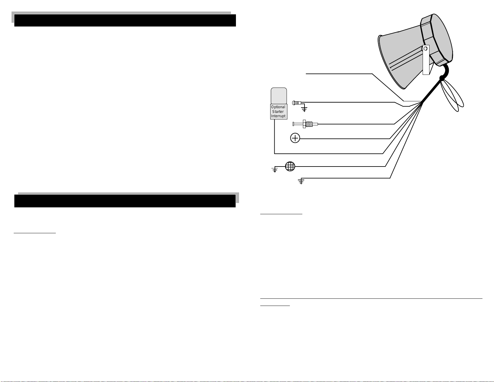
WIRING DIAGRAM OVERVIEW
Green Wire Loop - Current Sensing-
Uncut: When the security system is armed, current
sensing can detect an electrical current spike from
the vehicle's battery and trigger the security system.
Cut: The Current Sensing feature will not operate.
BLACK ANTENNA WIRE
Do Not Connect To Anything
- Stretch Out and
Secure
Relay
Optional
Starter
Interrupt
ORANGE WIRE
PINK WIRE
BLUE WIRE
RED WIRE
WHITE WIRE
BLACK WIRE
Ground
- Positive Output for LED
- Negative Instant Trigger
- Constant 12 Volts Positive
- Ground Output While Armed
- Output To Parking Lights
- Connect To
Page - 10
-
White Wire Loop - 3 Minute
Current Sensing Delay
Cut : The Current Sensing
feature can trigger the alarm
as soon as it is fully armed.
Uncut: This feature will wait 3
minutes after arming before
it can trigger the alarm.
Wiring Connections
Short Black Ground Wire:
The Black wire's function is to supply chassis ground for the alarm's operation.
CONNECTION:
Connect the Black wire to the metal frame of the vehicle with a ring terminal, preferably
using an existing machine-threaded fastener. Make sure that the Black wire's ring terminal
has contact with bright, clean metal. If necessary, scrape any paint, rust or grease away from
the connection point until the metal is bright and clean. Note: If you have a bad ground
connection, the alarm can find partial ground through the wires that are connected to other
circuits, but the alarm will not function correctly, making you think you have a defective
alarm. The alarm can partially work, so you would never suspect a bad ground wire
connection. In some cases the alarm could arm and disarm properly but not function
correctly otherwise. Note: We recommend that this connection be made first.
Red Constant 12 Volt Positive Wire:
The Red wire's functions are:
1) To supply constant 12 volt positive for alarm system's operation.
2) After the system is armed, and if the Current Sensing feature is utilized, if any electrical
device in the vehicle turns on (i.e. the dome light), the current spike would be sensed
by the Red wire to trigger the system, which will sound the siren, and flash the lights.
3) When 12 volts is first applied to the Red wire, the system will enter self diagnostic and
code learning mode.
Page - 11
Continued Next Page
4) To supply 12 volts to the built-in relay contacts for the security system's White flashing
parking lights wire.
CONNECTION:
For dependable current sensing, connect the Red wire to a Constant 12 Volt wire at the
ignition switch. This wire will have 12 volt positive at all times and in all ignition key
positions. Another location can be at the constant 12 volt wire behind the fuse block or the
fuse/junction block. Connecting directly to the battery's positive terminal is not recommended due to the corrosive environment and poor current sensing. Never just insert this
wire behind a fuse. The connection location must have constant 12 volt, 15 amp capacity.
Many vehicles have an engine compartment fuse/relay block where this connection can be
made.
Long Black Antenna Wire:
The long Black wire attached to the alarm's control unit is the antenna wire.
Do not connect this wire to anything or your transmitter's range will be reduced or
eliminated. Stretch this wire out and as high as possible for the best operating range. Keep
this wire away from metal as much as practical, and it may be tie-wrapped to plastic parts.
Blue Negative Instant Trigger Wire:
The Blue wire's function is a Negative instant trigger used primarily to detect entry into
the hood or trunk area of a vehicle. It may also be connected to negative door pin switches
which turn on the dome light. Complete functions are:
1) If the Blue wire is grounded after alarm has armed, the alarm will trigger.
Page - 12
Page 4
2) If the blue wire is grounded when the alarm is armed, the blue wire circuit will be
unprotected until it becomes ungrounded. The alarm, however, will not trigger upon
arming if the Blue wire is grounded.
3) If the Blue wire triggers the alarm, the disarm confirmation will change to four siren
chirps, four parking light flashes and the LED Status Light will flash 3 times between
pauses for 20 seconds to indicate that the alarm was triggered by negative instant trigger
wire.
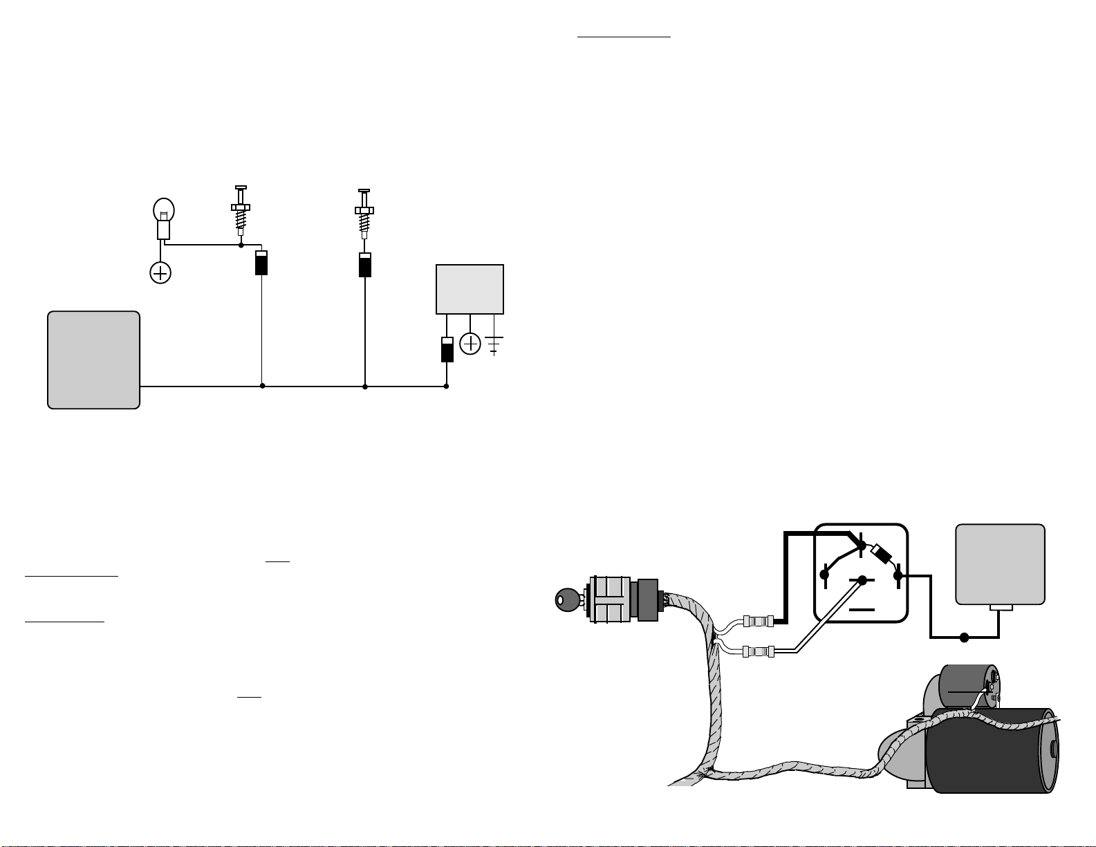
DIAGRAM FOR DIODE ISOLATING MULTIPLE BLUE WIRE USES
Trunk
Light
Trunk
Pin
Switch
Hood
Pin
Switch
Note: Use IN4002
Diodes, Which May
Be Found At Most
Electronics Stores.
Optional
Electronic
Sensor
Alarm
Control
Unit
Blue (-) Instant Trigger Wire.
Page - 13
Orange Grounded Output While Armed Wire:
The Orange wire is for an optional starter disable socket and relay. The function of
this wire is to provide a constant 500ma ground output whenever the alarm is armed. This
ground output supplies one side of the relay's coil. The other side of the relay coil will be
supplied with positive voltage from the ignition switch, but only if the ignition switch is
turned to the "start" position. If this occurs, the coil will energize, triggering the relay,
which in turn will open the starter circuit. The starter interrupt prevents the vehicle from
starting only if the alarm is armed (including while the alarm is triggered), and will draw
current from the vehicle's electrical system only if an attempt is made to start the vehicle.
CONNECTION:
To interrupt the vehicle's starter circuit, the starter wire must be located and cut. We
recommend that this be done as close to the ignition switch as possible. Use a voltmeter,
not a test light, to find the correct wire, which is the wire from the ignition switch to the
starter solenoid.
CAUTION! Improper use of a test light can cause deployment of the airbag, which may
result in bodily injury! Test lights can also damage expensive on-board computers and
associated sensors.
The starter wire will read 12 volts only when ignition key is in "start" position (cranking
the engine). Cut this wire at a suitable location. Confirm that this is the correct wire by
turning the ignition switch to the "start" position. The starter should not engage. Now that
the starter wire has been cut, there are two sides - the ignition switch side and the starter
solenoid side. Connect the starter disable socket's Red wire to the ignition switch side, and
its White wire to the starter solenoid side. Be sure that you make good, solid electrical
connections as this is a high amperage circuit. Connect the alarm's Orange wire to the
Orange wire of the starter disable socket.
Page - 15
Continued Next Page
Continued Next Page
CONNECTION:
The included pin switch may be installed to provide this trigger circuit Or, if there are
existing switches (example: a light in the luggage compartment or a "Trunk Ajar" light in
the dash), the Blue wire may be connected directly, provided this is a negative ground
switching circuit. An indication of such a circuit is the wire having no voltage present when
the hood or trunk is open, and up to 12 volts when the hood or trunk is closed. This circuit
cannot be used with mercury switch types of hood or trunk lights. If the vehicle is equipped
with a usable trunk or hood circuit, locate the proper wire and splice the Blue wire directly
to the vehicle's wire.
When wiring more than one of the vehicle's circuits and/or additional circuits to this
wire, diode-isolation may be required to maintain each circuit's proper operation. An
example would be wiring a hood pin switch and trunk light switch together. Without
isolating, the trunk light will illuminate whenever the hood is raised. Also, diode-isolation
is necessary when combining electronic sensors together ,or, in the same circuit with pin
switches. See the diagram on the previous page.
Page - 14
Although a relay can be wired without using the starter disable socket, we recommend
using the socket. Besides being easier and faster than wiring a relay, the socket includes a
diode that prevents the relay from inductive lockup, which will prevent the vehicle from
being started. When wiring a relay without the socket, use the following diagram:
Starter Disable Socket Red Wire To
The Ignition Switch Side Of The Cut.
30
86 87a 85
Alarm
Control
Unit
87
Ignition
Switch
Cutting The Vehicle's
Starter Wire Will Leave
Two Sides- The Ignition
Switch Side And The
Starter Solenoid Side.
Socket
Orange
Wire
Starter Disable Socket White
Wire To The Starter Solenoid
Side Of The Cut.
Page - 16
Control
Module
Orange
Wire
Starter
Solenoid
Page 5

White Flashing Parking Light Output Wire:
3
3
3
3
3
3
3
3
3
9
9
9
9
9
9
9
9
9
4
4
4
4
4
4
4
4
4
9
9
9
9
9
9
9
9
9
The White wire is a positive 12 volt output for exterior flashing light confirmation, and,
to attract attention to the vehicle if the alarm is triggered.
CONNECTION:
Connect this wire to the vehicle's positive 12 volt parking light circuit. This wire can
usually be found at the following locations: at a parking light, at the headlight switch, at the
fuse/junction block. Some vehicles, notably Toyotas, have a parking light relay which is
triggered by a ground circuit from the headlight switch. These cars can still be connected
directly to the White wire by finding the parking light circuit after the relay, usually at the
Fuse/Junction Block.
The correct wire will show positive 12 volt when the headlight switch is in the "Parking
Light" and "Head Light" positions. When such a wire is located, be sure to also test that it
is non-rheostated: while metering the wire, operate the dash light dimmer control. The
correct wire will show no change in voltage when the dimmer is operated. Note: Do not
attempt to flash the parking lights by connecting the White wire to a rheostated (dimmer)
circuit! This will backfeed the parking lights through the rheostat or illumination control
module, and possibly cause damage to the vehicle or alarm control unit. Also, if the White
wire touches chassis ground, the Printed Circuit Board and on-board relay will be damaged.
When left & right parking lights are on separate circuits, a pair of 6 to 10 amp diodes
or a pair of relays must be used to connect the White wire to each parking light side. The
following diagrams show both methods.
Flashing the headlights is not recommended. The halogen headlights furnished in
modern vehicles are not designed to be rapidly turned on and off. If connected to the
alarm system, a reduction of their useful life may be noticed. If flashing the headlights is
still desired, a relay must be used, since the headlight's current draw exceeds the 7 amp
Page - 17
Continued Next Page
LEFT AND RIGHT PARKING LIGHTS USING TWO RELAYS
Alarm
White Wire
Control
Unit
86
C O I L
ff
85
87
87A
30
86
C O I L
85
87
87A
30
Right Parking Lights
Light
Switch
To Constant
12 Volt
23
2345678
23
2345678
23
2345678
23
2345678
23
2345678
23
2345678
23
2345678
23
2345678
23
2345678
rating of the on-board relay. If flashing headlights and parking lights are desired, use the
diagram for left and right parking lights using two relays. Any application that requires
more than 7 amps of output must use an external relay.
LEFT AND RIGHT PARKING LIGHTS USING TWO DIODES
Alarm
Note: Use Two
IN4006 Diodes.
White
Wire
Page - 18
Pink LED Status Light Wire:
The Pink wire is an output for the Red LED Status Light, which informs you of the alarm
system's armed, disarmed, and triggered state. Included is a case to hold the LED Status Light
and double-sided adhesive tape, allowing it to be mounted to an interior surface without
drilling a hole. The LED Status Light will indicate 10 conditions in which the alarm system
can be in:
1) Off = The Alarm Is Disarmed.
2) Flashing Fast = 5 Second Arming Delay After The Single Confirmation Chirp.
3) Flashing Slow= The Alarm Is Fully Armed, And Can Be Triggered.
The following LED Status Light codes will flash for 20 seconds after the alarm is disarmed:
4) Flash Once and Pause = One Transmitter Is Coded To The Alarm.
5) Flash Twice and Pause = Two Transmitters Are Coded To The Alarm.
6) Flash Three Times and Pause = Three Transmitters Are Coded To The Alarm.
7) Flash Four Times and Pause = Four Transmitters Are Coded To The Alarm.
The following LED Status Light codes will flash for 20 seconds after the alarm is
disarmed only if the alarm system was triggered while you were away:
8) Flash Once and Pause = The Alarm Was Triggered By Current Sensing.
9) Flash Twice and Pause = The Alarm Was Triggered From The Shock Sensor.
10)Flash Three Times and Pause = The Alarm Was Triggered From The Instant
Trigger Circuit.
Control
Unit
Right Parking Lights
Light
Switch
Left Parking Lights
2
2345678
2
2345678
2
2345678
2
2345678
2
2345678
2
2345678
2
2345678
2
2345678
2
2345678
Page - 19
Left Parking Lights
Page - 20
Page 6

CONNECTION:
After mounting the LED Status Light, ground the Black wire to chassis ground, using
the terminal provided. Route the Pink wire to the alarm control unit's Pink wire and plug
together.
LED STATUS LIGHT MOUNTING AND WIRING
Pink Wire
Alarm
Control
Unit
Pink Wire
Black Wire
Plug-In
LED Status
Indicator
Programming The Alarm Control Module To The Transmitter:
The alarm system is capable of being operated from up to 4 separate transmitters. The
alarm "learns" the transmitter's code, and will retain the transmitter codes for approximately
24 hours if its 12 volt power is removed. Depending upon on how long the alarm has been
unpowered, one of two transmitter code learning procedures are followed:
Code Learning Method #1: If the alarm has not been supplied power for more than 24 hours
there will be no codes stored. Upon power-up, the unit will enter the transmitter code
learning mode. At any time after this point press the large transmitter button. The alarm will
confirm that the code was learned by responding with a siren burst and then a chirp. After
this confirmation, there is a 20 second period in which the second transmitter may be
learned. When the second transmitter's large button is pressed, the alarm will respond with
a siren burst and two chirps. If additional transmitters are learned, the response will be a siren
burst and three chirps, then a siren burst and four chirps, until the maximum four transmitters
are learned. Only the large transmitter button needs to be pressed. The alarm will
automatically respond to the small button when it is used. The alarm will be removed from
the transmitter code learning mode from these operations: first, 20 seconds of no transmitter
activity; second, pressing the same transmitter's large button again, which will arm the
system, or third, having the alarm learn the maximum of four transmitters.
Code Learning Method #2: If the alarm has been without power for less than 24 hours the
existing transmitter codes will be retained. Upon powering up the alarm, if a transmitter
whose code is stored in the alarm's memory is used, pressing its large button will arm the
alarm, which also removes it from the code learning mode. If, however, a transmitter is
used that is not in the alarm unit's memory, the existing codes will be removed. This is
important to remember, for if a third or fourth transmitter is being coded to an existing
Page - 21
alarm system, the alarm may be unpowered for more than 24 hours; or, by using the
following procedure:
Since entering an unknown transmitter will erase all stored codes, and entering a known
transmitter code will end the code learning mode, this procedure must be followed: When
coding an additional transmitter, the new transmitter code must be presented first, then the
original transmitters must be relearned.
Regardless of which method is employed to code transmitter to the alarm control unit,
remember that the alarm unit is also in self diagnostic mode. If the Blue negative instant
trigger wire is grounded, or becomes grounded while attempting to learn transmitter codes,
the alarm will not accept the transmitter codes. This condition will be indicated by the siren
chirping three times.
Operating A Second Vehicle's Alarm: When the second vehicle's alarm is in the
transmitter learn mode, press both of the first vehicle's transmitter buttons. On this
transmitter, the first vehicle will arm and disarm from transmitter's large button, and the
second from the large and small buttons pressed together. The small button will still work
normally.
Sometimes You Have To Transmit Close To The Vehicle:
This F.C.C. approved Radio Frequency car alarm must accept any interference it may
be subject to. If you are parked close to a radio tower or other areas where there is a high
level of interference, you may need to get closer to the vehicle. If this is not the case, you
should check the system antenna, if you experience low operating range all the time.
Reposition the antenna to a different position. If you have not securely connected the red or
black power wires you could also experience low range. Replace your transmitter battery
if its red LED light is weak.
Page - 23
Page - 22
L I M I T E D L I F E T I M E W A R R A N T Y
Products manufactured and sold by OMEGA RESEARCH & DEVELOPMENT, INC. (the Company),
are warranted to be free from defects in materials and workmanship under normal use. If a product sold by
the Company proves to be defective, the Company will repair or replace it free of charge within the first year
and thereafter all parts to be repaired will be free with only a nominal charge for Omega Research and
Development, Inc.'s labor and return shipping, to the original owner during the lifetime of the car in which
it was originally installed.
All products for warranty repair must be sent postage prepaid to Omega Research & Development, Inc.,
P.O. Box 508, Douglasville, Georgia 30133, with bill of sale or other dated proof of purchase. This warranty
is nontransferable and does not apply to any product damaged by accident, physical or electrical misuse or
abuse, improper installation, alteration, any use contrary to its intended function, unauthorized service, fire,
flood, lightning, or other acts of God.
This warranty limits the Company's liability to the repair or replacement of the product. The Company
shall not be responsible for removal and/or reinstallation charges, damage to or theft of the vehicle or its
contents, or any incidental or consequential damages caused by any failure or alleged failure of the product
to function properly. Under No Circumstances Should This Warranty, Or The Product Covered By It, Be
Construed As A Guarantee Or Insurance Policy Against Loss. The Company neither assumes nor authorizes
any person or organization to make any Warranties or assume any liability in connection with the sale,
installation, or use of this product.
This device complies with FCC Rules part 15. Operation is subject to the following two
conditions, (1) This device may not cause harmful interference and, (2) This device must
accept any interference that may be received, including interference that may cause
undesired operation.
The manufacturer is not responsible for any radio or TV interference caused by unauthorized modifications to this equipment. Such modifications could void the user's authority to
operate the equipment.
MA_FRE-411ATV.REV2
 Loading...