

Page 1

User’s Guide
FPUD3-P
Shop online at
omega.com
e-mail: [email protected]
For latest product manuals:
omegamanual.info
Xxxxx Xxxxxxxx
XXXXXX
Page 2

OMEGAnet®Online Service Internet e-mail
U.S.A.:
ISO 9001 Certified
omega.com [email protected]
Servicing North America:
Omega Engineering, Inc., One Omega Drive, P.O. Box 4047
Stamford, CT 06907-0047 USA
Toll Free: 1-800-826-6342 TEL: (203) 359-1660
FAX: (203) 359-7700 e-mail: [email protected]
Canada:
976 Bergar
Laval (Quebec), Canada H7L 5A1
Toll-Free: 1-800-826-6342 TEL: (514) 856-6928
FAX: (514) 856-6886 e-mail: [email protected]
For immediate technical or application assistance:
U.S.A. and Canada: Sales Service: 1-800-826-6342/1-800-TC-OMEGA
Customer Service: 1-800-622-2378/1-800-622-BEST
Engineering Service: 1-800-872-9436/1-800-USA-WHEN
Mexico: En Español: 001 (203) 359-7803 FAX: (001) 203-359-7807
®
®
®
Servicing Europe:
Benelux:Managed by the United Kingdom Office
Czech Republic: Frystatska 184
733 01 Karviná, Czech Republic
Toll-Free: 0800-1-66342 TEL: +420-59-6311899
FAX: +420-59-6311114 e-mail: [email protected]
France:
Managed by the United Kingdom Office
Toll-Free: 0800 466 342 TEL: +33 (0) 161 37 29 00
FAX: +33 (0) 130 57 54 27 e-mail: [email protected]
Germany/Austria: Daimlerstrasse 26
D-75392 Deckenpfronn, Germany
Toll-Free: 0 800 6397678 TEL: +49 (0) 7059 9398-0
FAX: +49 (0) 7056 9398-29 e-mail: [email protected]
United Kingdom: OMEGA Engineering Ltd.
ISO 9001 Certified One Omega Drive, River Bend Technology Centre, Northbank
Irlam, Manchester M44 5BD England
Toll-Free: 0800-488-488 TEL: +44 (0)161 777-6611
FAX: +44 (0)161 777-6622 e-mail: [email protected]
It is the policy of OMEGA Engineering, Inc. to comply with all worldwide safety and EMC/EMI
regulations that apply. OMEGA is constantly pursuing certification of its products to the European New
Approach Directives. OMEGA will add the CE mark to every appropriate device upon certification.
The information contained in this document is believed to be correct, but OMEGA accepts no liability for any
errors it contains, and reserves the right to alter specifications without notice.
WARNING: These products are not designed for use in, and should not be used for, human applications.
1
Page 3

Introduction
The FPUD3 Series drum pumps feature corrosion-resistant construction and can empty a wide variety of containers in various ap-
plicaitions. FPUD4 Series are rated for 2,000 cps viscosity and 1.8 SG. FPUD5 Series pumps are for high viscosity applications for
fluids up to 15,000cps viscosity. FMSD11 Series mixers efficiently mix from the top of a drum to the bottom with a non-vortexing,
non-aeratingaction. These mixers can draw approximately 14 gallons of liquid per minute through a 2” diameter mixing tube up to
750 cps maximum viscosity.
Index
Introduction ............................................................................................................................. 2
Safety ...................................................................................................................................... 3
Pump Specifications ................................................................................................................ 4
Installation ............................................................................................................................... 5
Maintenance
Disassembly ....................................................................................................................... 5
Inspection ........................................................................................................................... 6
Reassembly ........................................................................................................................ 6
Exploded View ......................................................................................................................... 7
Pump Tube Spare Parts List ..................................................................................................... 8-9
2
Page 4

Safety
1. Introduction
This manual contains all information needed for the correct installation, use and maintenance of your new Omega Engineering
pump. It should be read and understood by all personnel involved in installation, operating and servicing of the pump before
it is started.
2. Operator Qualification and Training
The personnel in charge of the installation, the operation, and the maintenance of the pump must be qualified and able to per form the operations described in this manual. Omega shall not be held responsible for the training level of
personnel and for the fact that they are not fully aware of the contents of this manual.
3. Safety Instructions
FOR YOUR OWN SAFETY
BEFORE using or servicing your pump, please make sure to wear the proper clothing, eye protection and follow standard safety
procedures when handling corrosive or personally harmful materials.
GENERAL DANGER
NEVER use a plastic pump or an open, splash-proof, TEFC or non-ATEX motor when pumping or mixing flammable or combus tible material.
ALWAYS use and store the pump and motor in an upright position.
DANGER: POWER SUPPLY
Refer to instructions in the appropriate motor Operation & Installation Manual.
4. Noise Level
Refer to specifications in the appropriate motor Operation & Installation Manual.
5. Modifications and Spare Parts
Any changes concerning the service of the pump as originally purchased can be executed only after written approval from
Omega Engineering. It is recommended to use only Omega spare parts and approved accessories. The use of non-Omega
spare parts or non-approved accessories will void warranty and removes any responsibility on the manufac turer’s behalf for any damage caused to people or things.
6. Cleaning
It is highly recommended to flush pumps with clean water or some other neutralizing fluid compatible with pump materials
when done pumping or when switching chemicals.
3
Page 5
INSTALLATION & MAINTENANCE INSTRUCTIONS
Installation
1. Remove the drum pump from its packaging and inspect for shipping damage.
2. Turn the pump coupling to verify there is no binding.
3. Verify the housing cover (item 21) is on tight (it has a left hand thread).
4. Adjust the coupling so that the empty slots in the insert are at 3 and 9 o’clock with the pump dis charge at 12 o’clock.
5. Install the motor onto the drum pump per the installation instructions from the Operation & Installation
Manual of the specific motor model.
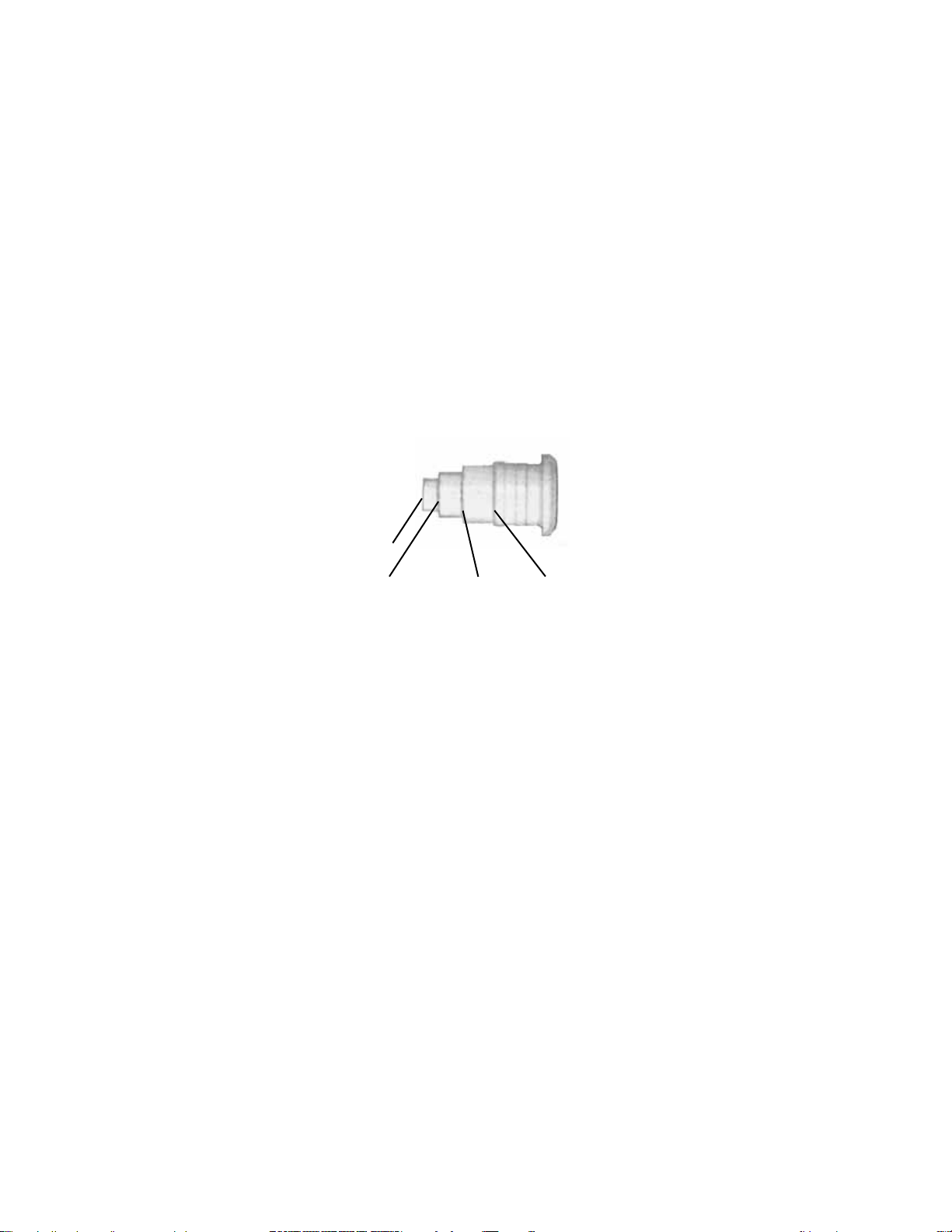
Note: Pumps with the standard 1” barb spout include a variable orifice fitting, which initially limits the flow of the
pump to 10 gpm. As it is cut away, flow will increase from 10 gpm up to maximum flow (to increase flow,
simply trim back orifice). Orifice steps control flow as follows: Step 1 = 10 gpm, Step 2 = 20 gpm, Step 3 = 30
gpm, Step 4 (maximum opening) = maximum flow (see Fig. 1).
Fig. 1
Step 1
Step 2
Note: ALWAYS use a 1” I.D. hose properly secured to the barb spout using a hose clamp.
Step 3
Step 4
Maintenance
Disassembly
1. Remove the housing cover (item 21) by turning it clockwise (left hand thread) while gripping the impeller
housing (item 18).
2. Turn the impeller until a hole in the shaft can be seen through the square slot in the impeller housing (item
18), and insert 3/32 pin into the hole. Holding the pin, turn the impeller (item 20) counterclockwise (right-
hand thread) and remove it.
3. Remove the impeller housing (item 18) by gripping the intake tube and spinning the housing clockwise
(left hand thread). Re-insert the 3/32 pin and while gripping the pump coupling unthread (counterclock-
wise) and remove the shaft (item 19) from the bearing assembly (item 3).
4. Place the pump head (item 5) in a vise (do not crush) and remove the intake tube (item 9) by unthreading
clockwise (left hand thread). Remove the inner upper (item 11) and lower (item 15) tubes from the head.
Remove the bearing assembly (item 3) and the FKM lip seal (item 4) from the head.
5. Remove the center bearing (item 13) from the upper (item 11) and lower (item 15) tubes.
5
Page 6

Inspection
1. Check the housing cover (item 21), the impeller (item 20), and the impeller housing (item 18) for wear, rubbing, or damage from foreign objects. Replace if damaged.
Note: The double impeller design of this pump is dependant on the impeller working correctly. Any damage
to the impeller can cause pump failure.
2. Inspect the pump shaft (item 19) for wear in the bottom (item 16), center bearing (item 13) and the FKM lip
seal (item 4) areas. Replace the shaft if needed.
3. Inspect the bottom bearing (item 16), center bearing (item 13), and the bearing guide (item 14) for internal
wear. Inspect all o-rings (items 17,12, & 10) for nicks or chemical attack. Replace as needed.
4. Inspect the bearing assembly (item 3) for rust or corrosion. Never reuse the lip seal.
Reassembly
1. Install new lip seal (item 4) into the pump head with the grooved side facing the bottom of the pump.
2. Thread the shaft (item 19) into the bearing assembly (item 3) with the 3/32 hole in the shaft on the other
end. Carefully insert the shaft straight through the vapor seal (to avoid seal damage) from the top and seat
the bearing assembly (item 3) into the pump head.
3. If o-rings are replaced -- install 2 center bearing o-rings (items 12) in the grooves, then slide the bearing
guide on and then the remaining 2 o-rings. Install 2 upper inner tube o-rings (items 10), and install the impeller housing o-ring (item 17) inside the top of the housing. Apply a small amount of Vaseline to the o-rings
to aid in assembly. Assemble the center bearing (item 13) into the upper (item 11) and lower (item 15) inner
tubes.
4. Slide the inner tube assembly up the shaft and into the counter bore in the bottom of the head. Slide the
intake tube up from the bottom, centering the bearing guide, and thread it into the head (left hand thread).
5. Gripping the coupling at the top of the pump, thread the impeller on (right hand thread). Install the housing
cover (left hand thread). Turn the coupling to verify there is no binding inside the pump.
6
Page 7
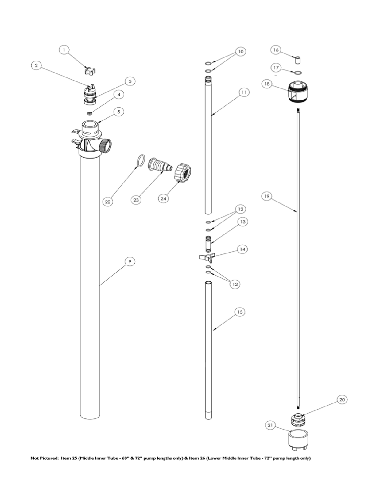
FPUD3-P SPARE PARTS EXPLODED VIEW
7
Page 8
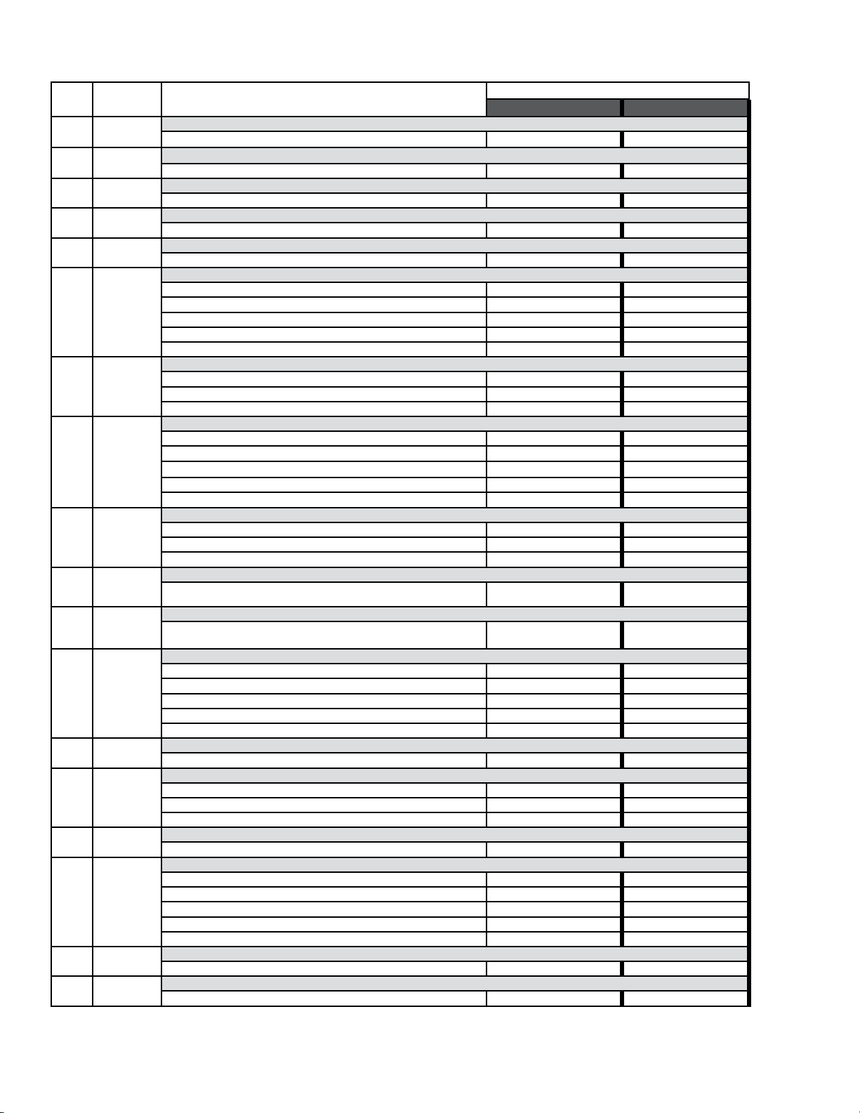
PUMP SPARE PARTS LIST
ITEM QTY DESCRIPTION
1 1
2 1
3* 1
4* 1
5 1
9 1
10* 2
11 1
4 (27-48”)
12*
8 (60”)
12 (72”)
1 (27-48”)
13
2 (60”)
3 (72”)
1 (27”-48”)
14
2 (60”)
3 (72”)
15 1
16 1
17* 1
18* 1
19 1
20* 1
21* 1
COUPLING INSERT
COUPLING HALF
BEARING ASSEMBLY
LIP SEAL
1/4” FKM 107592 107592
PUMP HEAD
POLYPROPYLENE 107755-1 107755-1
INTAKE TUBE
27” MODELS 107475-2 107475-2
40” MODELS 107475-3 107475-3
48” MODELS 107475-4 107475-4
60” MODELS 107475-5 107475-5
72” MODELS 107475-6 107475-6
UPPER INNER TUBE O-RING
FKM J100249 J100249
EPDM 106519 106519
PERLAST 105621 105621
UPPER INNER TUBE
27” MODELS 107660-2 107660-2
40” MODELS 107660-3 107660-3
48” MODELS 107660-4 107660-4
60” MODELS 107660-3 107660-3
72” MODELS 107660-3 107660-3
CENTER BEARING O-RING
FKM J100018 J100018
EPDM 106798 106798
PERLAST 105620 105620
CENTER BEARING
PTFE M100010 M100010
BEARING GUIDE
POLYPROPYLENE M101603-2 M101603-2
LOWER INNER TUBE
27” MODELS M100003-1 M100003-1
40” MODELS M100003-3 M100003-3
48” MODELS M100003-4 M100003-4
60” MODELS M100003-3 M100003-3
72” MODELS M100003-3 M100003-3
BOTTOM BEARING
PTFE M100007 M100007
IMPELLER HOUSING O-RING
FKM J100019 J100019
EPDM 106799 106799
PERLAST 105622 105622
IMPELLER HOUSING
POLYPROPYLENE 107316-1 107316-1
MAIN SHAFT
27” MODELS M100004-5 M100004-1
40” MODELS M100004-7 M100004-3
48” MODELS M100004-8 M100004-4
60” MODELS M100004-12 M100004-9
72” MODELS M100004-13 M100004-11
IMPELLER ASSEMBLY
PVDF A100002-2 A100002-2
HOUSING COVER
PART NUMBER
FPUD3-P PFM FPUD3-P PFP
J100014 J100014
J100012 J100012
A101110 A101110
M101612-1 M101612-1
8
Page 9
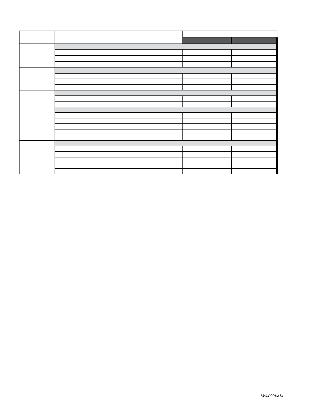
ITEM QTY DESCRIPTION
DISCHARGE O-RING
22 1
23 1
24 1
25
(not
pictured)
26
(not
pictured)
*Recommended Spare Parts
Note: Bearing assembly and lip seal can be purchased as a kit using part number 108110.
FKM J100991 J100991
EPDM J102378 J102378
PERLAST 107017 107017
SPOUT
1” BARB (STANDARD) M100028-1 M100028-1
3/4” BARB (OPTIONAL) 105439-1 105439-1
1” MNPT (OPTIONAL) 106599 106599
DISCHARGE NUT
FOR USE WITH 1” OR 3/4” BARB SPOUT M101610-1 M101610-1
FOR USE WITH 1” MNPT SPOUT ONLY 106622 106622
MIDDLE INNER TUBE
27” MODELS N/A N/A
40” MODELS N/A N/A
1
48” MODELS N/A N/A
60” MODELS M100003-3 M100003-3
72” MODELS M100003-3 M100003-3
LOWER MIDDLE INNER TUBE
27” MODELS N/A N/A
40” MODELS N/A N/A
1
48” MODELS N/A N/A
60” MODELS N/A N/A
72” MODELS M100003-1 M100003-1
PART NUMBER
FPUD3-P PFM FPUD3-P PFP
N/A = Not Applicable
M-5277/0313
Page 10

Where Do I Find Everything I Need for
Process Measurement and Control?
OMEGA…Of Course!
Shop online at omega.com
SM
TEMPERATURE
Thermocouple, RTD & Thermistor Probes, Connectors, Panels & Assemblies
Wire: Thermocouple, RTD & Thermistor
Calibrators & Ice Point References
Recorders, Controllers & Process Monitors
Infrared Pyrometers
PRESSURE, STRAIN AND FORCE
Transducers & Strain Gages
Load Cells & Pressure Gages
Displacement Transducers
Instrumentation & Accessories
FLOW/LEVEL
Rotameters, Gas Mass Flowmeters & Flow Computers
Air Velocity Indicators
Turbine/Paddlewheel Systems
Totalizers & Batch Controllers
pH/CONDUCTIVITY
pH Electrodes, Testers & Accessories
Benchtop/Laboratory Meters
Controllers, Calibrators, Simulators & Pumps
Industrial pH & Conductivity Equipment
DATA ACQUISITION
Data Acquisition & Engineering Software
Communications-Based Acquisition Systems
Plug-in Cards for Apple, IBM & Compatibles
Datalogging Systems
Recorders, Printers & Plotters
HEATERS
Heating Cable
Cartridge & Strip Heaters
Immersion & Band Heaters
Flexible Heaters
Laboratory Heaters
ENVIRONMENTAL
MONITORING AND CONTROL
Metering & Control Instrumentation
Refractometers
Pumps & Tubing
Air, Soil & Water Monitors
Industrial Water & Wastewater Treatment
pH, Conductivity & Dissolved Oxygen Instruments
M-5277/0313
 Loading...