

Page 1
User’s Guide
FPUD Series
Drum Pump Motors
Shop online at
omega.com
e-mail: [email protected]
For latest product manuals:
omegamanual.info
XXXXXX
Xxxxx Xxxxxxxx
Page 2

OMEGAnet®Online Service Internet e-mail
omega.com [email protected]
Servicing North America:
U.S.A.: Omega Engineering, Inc., One Omega Drive, P.O. Box 4047
ISO 9001 Certified Stamford, CT 06907-0047 USA
Canada:
976 Bergar
Laval (Quebec), Canada H7L 5A1
Toll-Free: 1-800-826-6342 TEL: (514) 856-6928
FAX: (514) 856-6886 e-mail: [email protected]
For immediate technical or application assistance:
U.S.A. and Canada: Sales Service: 1-800-826-6342/1-800-TC-OMEGA
Customer Service: 1-800-622-2378/1-800-622-BEST
Engineering Service: 1-800-872-9436/1-800-USA-WHEN
Mexico: En Español: 001 (203) 359-7803 FAX: (001) 203-359-7807
®
®
®
Servicing Europe:
Benelux:Managed by the United Kingdom Office
Czech Republic: Frystatska 184
733 01 Karviná, Czech Republic
Toll-Free: 0800-1-66342 TEL: +420-59-6311899
FAX: +420-59-6311114 e-mail: [email protected]
France: Managed by the United Kingdom Office
Toll-Free: 0800 466 342 TEL: +33 (0) 161 37 29 00
FAX: +33 (0) 130 57 54 27 e-mail: [email protected]
Germany/Austria: Daimlerstrasse 26
D-75392 Deckenpfronn, Germany
Toll-Free: 0 800 6397678 TEL: +49 (0) 7059 9398-0
FAX: +49 (0) 7056 9398-29 e-mail: [email protected]
United Kingdom: OMEGA Engineering Ltd.
ISO 9001 Certified One Omega Drive, River Bend Technology Centre, Northbank
Irlam, Manchester M44 5BD England
Toll-Free: 0800-488-488 TEL: +44 (0)161 777-6611
FAX: +44 (0)161 777-6622 e-mail: [email protected]
It is the policy of OMEGA Engineering, Inc. to comply with all worldwide safety and EMC/EMI
regulations that apply. OMEGA is constantly pursuing certification of its products to the European New
Approach Directives. OMEGA will add the CE mark to every appropriate device upon certification.
The information contained in this document is believed to be correct, but OMEGA accepts no liability for any
errors it contains, and reserves the right to alter specifications without notice.
WARNING: These products are not designed for use in, and should not be used for, human applications.
2
Page 3

TABLE OF CONTENTS
TABLA DE CONTENIDO
Safety Precautions .............................................. 4
Maintenance Precautions ................................... 4
Installation .......................................................... 5
FPUD311& FPUD311A Models ........................ 6
Assembly Drawing and Parts List
FPUD362 Models .............................................. 7
Assembly Drawing and Parts List
FPUD411 & FPUD421 Models ......................... 8
Assembly Drawing and Parts List
FPUD431 Model ................................................ 9
Assembly Drawing and Parts List
FPUD331Model ............................................... 10
Assembly Drawing and Parts List
FPUD500 Models .............................................11
Assembly Drawing
Precauciones de Seguridad ................................ 4
Precauciones de Mantenimiento ........................ 4
Instalación .......................................................... 5
Modelos FPUD311& FPUD311A ...................... 6
Dibujo de Armadura y Lista de Partes
Modelos FPUD362 ............................................ 7
Dibujo de Armadura y Lista de Partes
Modelos FPUD411 & FUD421 ......................... 8
Dibujo de Armadura y Lista de Partes
Modelo FPUD431 .............................................. 9
Dibujo de Armadura y Lista de Partes
Modelo FPUD331 ............................................ 10
Dibujo de Armadura y Lista de Partes
Modelo FPUD500 .............................................11
Dibujo de Armadura y Lista de Partes
3
Page 4

SAFETY
PRECAUCIONES DE
PRECAUTIONS
ALWAYS wear protective clothing, eye protection and follow
standard safety procedures when handling corrosive or personally harmful materials.
NEVER use a plastic pump or an open, splashproof or TEFC
motors when pumping or mixing ammable or combustible
material.
ALWAYS use and store in an upright position.
NEVER immerse motor in liquid.
ALWAYS place motor in the OFF position prior to connecting
the power source.
ALWAYS check motor label plate for the correct power supply
requirements.
ALWAYS use an approved plug for Class I, Division 1, Group
C & D applications on the explosionproof motors.
Noise level at a distance of 3 feet:
FPUD311 & FPUD311-A Series 73 db (Splash proof)
FPUD362 77 db (Totally enclosed
fan cooled)
FPUD431 (Air) 85 db (800 watt)
SEGURIDAD
SIEMPRE use ropa protectiva, protección para los ojos y siga
procedimentos de seguridad básicos cuando maneje materiales
corrosivos.
NUNCA use una bomba de plástico en los motores abiertos,
contra salpiqueos o TEFC cuando se bombéa o se mezcla
materiales combustibles o inamables.
SIEMPRE use y almacene recto.
NUNCA sumerga el motor en líquido.
SIEMPRE ponga el motor en la posición OFF antes de conectar
la corriente electrica.
SIEMPRE revise la placa por los requerimientos correctos de
corriente electrica.
SIEMPRE use un enchufe aprovado para la Clase I, la Division 1, las aplicaciones de los Grupos C & D en el motor de
la Serie X.
Nível de ruido a una distancia de 3 pies:
FPUD311 & FPUD311-A Series 73 db (Contra alpiqueos)
FPUD362 77 db (TEFC -Totalmente sellada con
ventilación)
FPUD431 (Aire) 85 db (800 watt)
MAINTENANCE
PRECAUTIONS
ALWAYS store motor upright and away from corrosive liquids
and vapors.
ALWAYS use an automatic air line lubricator, moisture trap
and lter in the airline ahead of an air motor. (Use detergent
SAE #10 in lubricator). Do not exceed 80 psi (551 kPa) on
FPUD431 air motors.
Motor Models FPUD311, FPUD311-A, FPUD362. Motor
brushes in these models should be replaced every 200-300
operating hours to assure trouble free service.
Motor Models FPUD311, FPUD311-A, FPUD362 contain a
circuit breaker (overload). If motor will not operate, check
the circuit breaker.
PRECAUCIONES DE
MANTENIMIENTO
SIEMPRE guarde el motor en una posición vertical lejos de
líquidos o vapores corrosivos.
SIEMPRE use un lubricador automático con trampa de hu-
medad y ltro en la línea de aire antes del motor. (Use el
detergente SAE número 10 en el lubricador). No excede de
80 psi (551 kPa) con el motor FPUD431.
Modelos de motor operan FPUD311, FPUD311-A, FPUD362 .
Los cepillos de motor en estos modelos deben ser reémplazados cada 200-300 horas de operación para asegurarse de un
servicio libre de problemas.
Modelos de motor FPUD311, FPUD311-A, FPUD362 contenen un disyuntor (sobrecarga). Si el motor no opera, revise
el disyuntor.
Page 5
INSTALLATION INSTALACIÓN
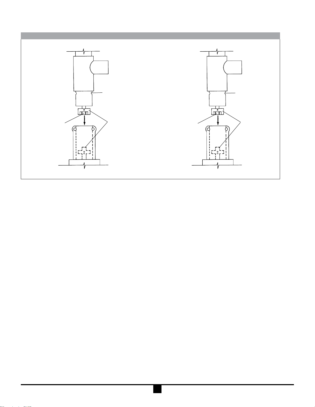
TUBE
GROOVE
COUPLING
INSERT
MOTOR WITH ADAPTER
Unpack motor from carton and check for shipping damage.
Unpack pump/mixer from carton and check for shipping
damage.
If any shipping damage is found, save the packaging and
notify the carrier immediately.
1. Ensure motor and pump compatibility. I.E., labeling.
2. Remove 2 socket head screws and nuts.
3. Ensure no obstructions on the coupling of either motor
or pump/mixer.
4. Position couplings and coupling insert for proper alignment.
5. Slide pump/mixer down into motor until couplings mate
and pump/mixer is seated properly. Refer to Figure 1.
6. Position motor so mounting holes line up with corresponding grooves on pump/mixer. (Note: Always position electric cord away from discharge spout of pump.)
7. Install 2 socket head screws and nuts in mounting holes
and tighten securely.
8. Check to ensure that the motor is secured to the pump/
mixer before operating. If not, repeat steps 1-6.
2 PRONG
COUPLING
Figure 1
TUBO
RANURA
INSERTO
ACOPLADOR
MOTOR CON ADAPTADOR
Saque el motor del cartón y revise por daños de embarque.
Saque la bomba (o mezclador) del cartón y revise por daños
de embarque.
Si se encuentran daños de embarque, póngase en contacto
con el suplidor del producto para reémplazarlo o reparario.
1. Asegúrese de la compatibilidad entre el motor y la
bomba. I.E. La etiqueta.
2. Remove 2 tornillos de cabeza de caquillo y tuercas.
3. Asegúrese de que no haya obstrucciones en el acoplador de el motor o la bomba (o mezclador).
4. Coloque el acoplador y el inserto acoplador para una
alineación correcta.
5. Deslize la bomba (o mezclador) hacia abajo en el motor
hasta que el acoplador y la bomba (o mezclador) esten
asentadas correctamente. Vea la Figura 1.
6. Coloque el motor para que los huecos de la estructura y
las ranuras correspondientes esten alineadas en la bomba (o mezclador). (Note: Siempre coloque la conexión
electrica lejos del caño de descargar de la bomba.)
7. Instale 2 tornillos de cabeza de caquillo y tuercas en los
huecos de la estructura y aprietelos seguros.
8. Revise para asegurarse que el motor esté amarrado a la
bomba (o mezclador) antes de operar. Si no está, repita
los pasos 1-6.
2 PUNTA
ACOPLADORA
5
Page 6
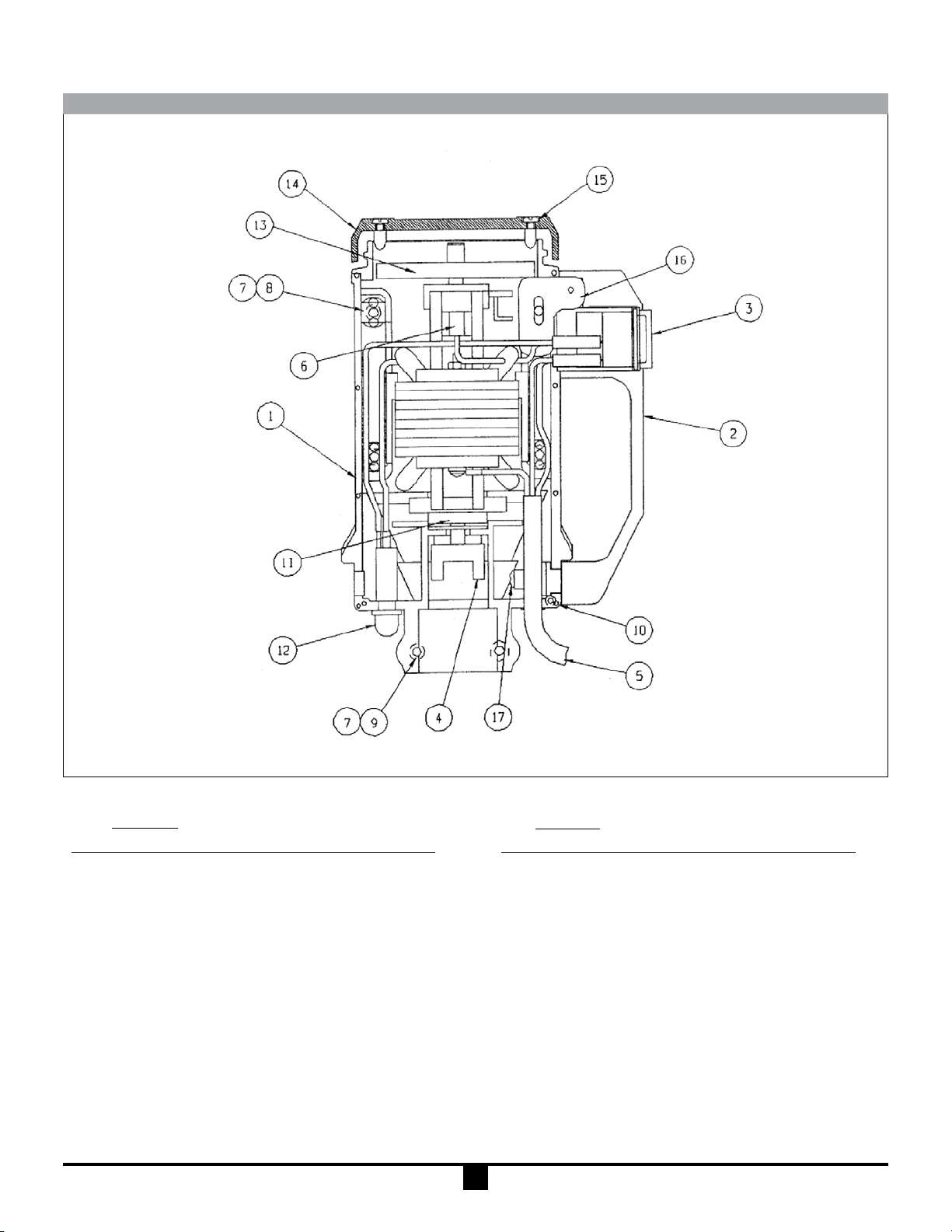
FPUD311 & FPUD311A MODELS
Item M3 M5 Description Part Number
1 1 1 HSG Repair Kit A101493
2 1 1 Handle M101668
3 1 1 Switch A101690
4 1 1 Half Coupling J100012
5 1 – Cord Assembly A102050
5 – 1 Cord Assembly A102051
6 2 2 Brush 107764
7 6 6 Housing Nut J100990
8 4 4 Housing Screw J100022
9 2 2 Mounting Screw J100023
QuantityQuantity
Item M3 M5 Description Part Number
10 3 3 Screw J102275
11 1 1 Bearing Kit A101018
12 1 – Circuit Breaker w/Cover A100854
12 – 1 Circuit Breaker w/Cover A102182
13 1 1 Fan Blade J101510
14 1 1 Motor Fan Cover M101710
15 4 4 Cover Screw J101020
16 1 1 Handle Mounting Block M101666
17 2 2 Screw J103715
Note: Motor housing repair kits include motor covers, labels
and screws to repair the motor should it be damaged.
6
Page 7
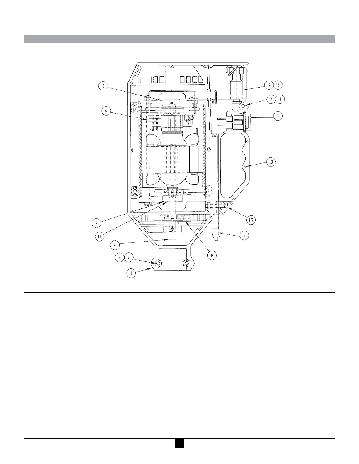
FPUD362 MODELS
Quantity Quantity
Item M3T M5T Description Part Number
1 1 1 HSG Repair Kit A101416
2 2 2 Ball Bearing J101069
3 1 1 Switch A101690
4 1 1 Half Coupling J100013
5 1 – Cord Assembly A101738
5 – 1 Cord Assembly A101740
6 2 2 Brush J101107
7 6 6 Housing Nut J100990
Note: Motor housing repair kits include motor covers, labels and screws to repair the motor should it be damaged.
Item M3T M5T Description Part Number
8 4 4 Housing Bolt J100023
9 2 2 Mounting Bolt J101690
10 2 2 Screw J101530
11 1 1 Wave Washer J101126
12 1 – Circuit Breaker J103796
12 – 1 Circuit Breaker J101149
13 1 1 Cover J100789
14 1 1 Fan Blade J101094
15 2 2 Housing Bolt J100022
7
Page 8
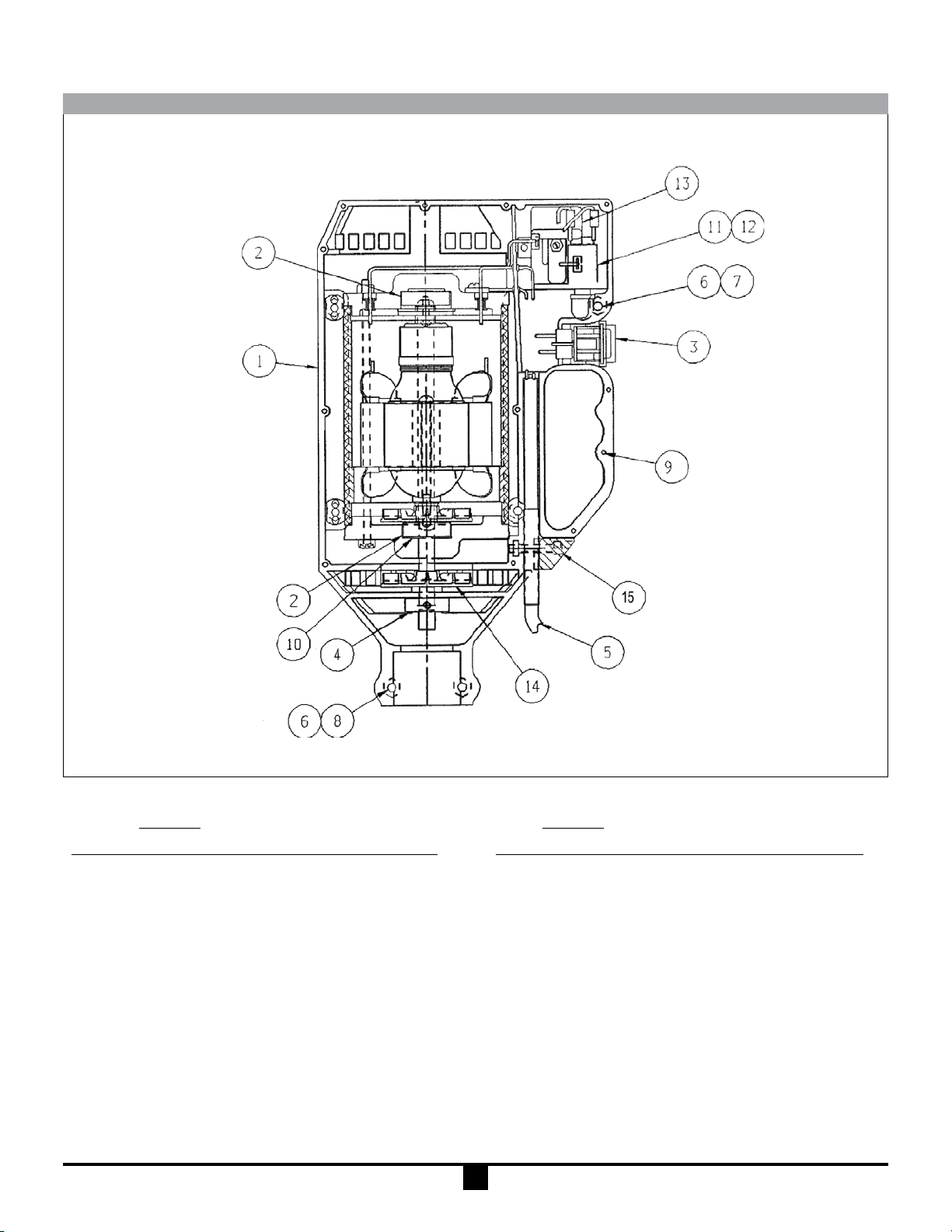
FPUD411 & FPUD421 MODELS
Quantity Quantity
Item M7T Description Part Number
1 1 Housing Repair Kit A101416
2 2 Ball Bearing J101069
3 1 Switch A101690
4 1 Half Coupling J100013
5 1 Cord Assembly A101748
5 – Cord Assembly A101751
6 6 Housing Nut J100990
7 4 Housing Bolt J100023
8 2 Mounting Bolt J101690
Notes: (1) Motor housing repair kits include motor covers, labels and screws to repair the motor should it be damaged.
(2) Contact factory for information on M8T.
Item M7T Description Part Number
9 2 Screw J101530
10 1 Wave Washer J101126
11 1 Circuit Breaker J101150
11 – Circuit Breaker J101149
12 1 Cover J100789
13 1 Start Relay J101147
13 – Start Relay J101804
14 1 Fan Blade A102024
15 2 Housing Bolt J100022
8
Page 9
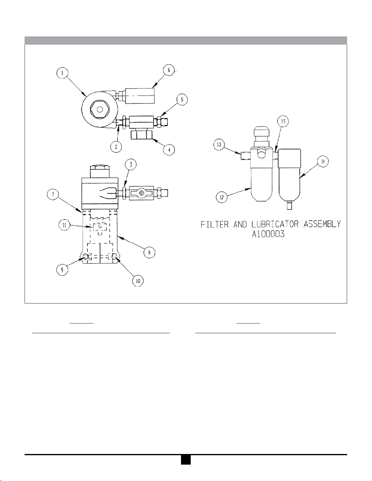
FPUD431 MODEL
Quantity
Item M6 Description Part Number
1 1 Air Motor M101717
2 1 Pipe Nipple J100107
3 1 Hex Red. Bushing J100057
4 1 Ball Valve J100073
5 1 Hose Fitting J100036
6 1 Mufer J100033
7 2 Set Screw J100040
Not Shown: Air Motor Repair Kit J100060
Quantity
Item M6 Description Part Number
8 1 Air Motor Mount M100013-1
9 2 Socket Head Cap Screw J100023
10 2 Hex Nut J100990
11 1 Half Coupling J100013
12 1 Lubricator J100035
13 2 Pipe Nipple J102463
14 1 Filter J100034
9
Page 10
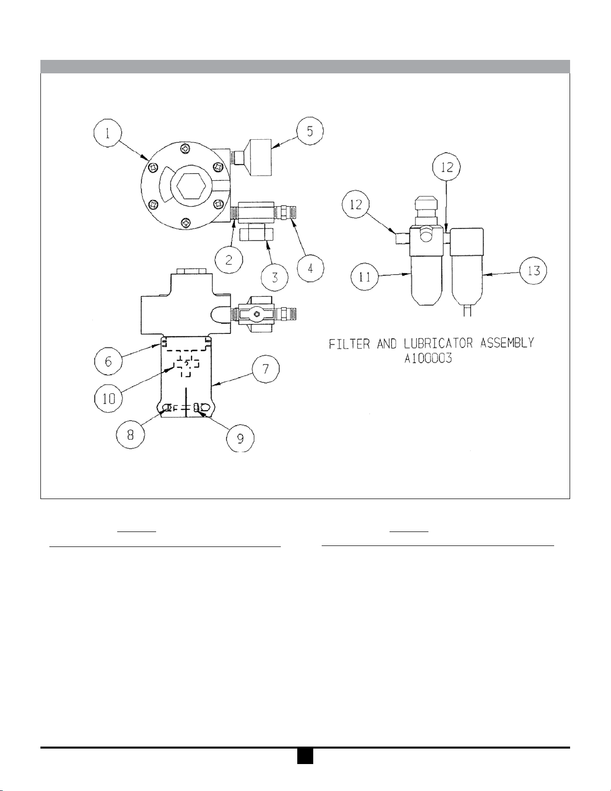
FPUD331 MODEL
Quantity
Item M6X Description Part Number
1 1 Air Motor M101720
2 1 Pipe Nipple J102463
3 1 Ball Valve J100073
4 1 Hose Fitting J100036
5 1 Mufer J100074
6 2 Set Screw J100040
7 1 Air Motor Mount M100013-2
Not Shown: Air Motor Repair Kit J100075
Quantity
Item M6X Description Part Number
8 2 Socket Hd. Cap Screw J100023
9 2 Hex Nut J100990
10 1 Half Coupling J101500
11 1 Lubricator J100035
12 2 Pipe Nipple J102463
13 1 Filter J100034
10
Page 11
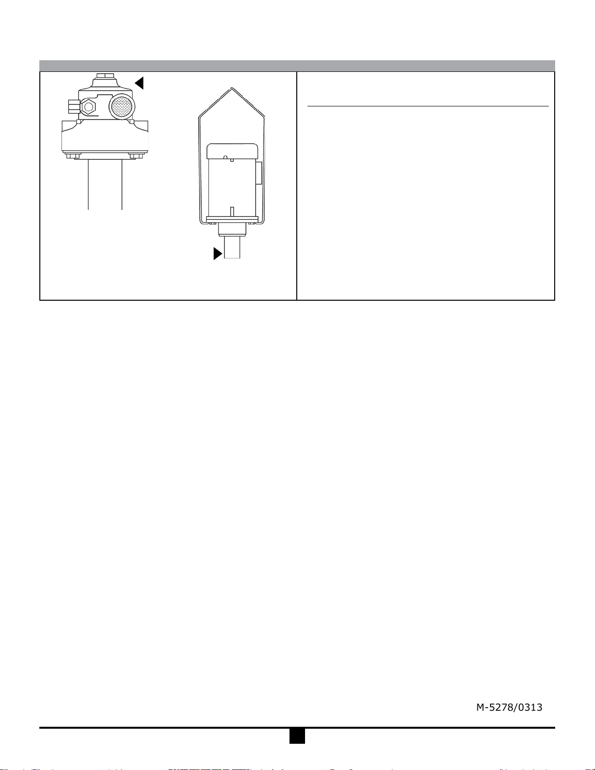
FPUD550 MODEL
BT AIR
BT ELECTRIC
M18 M15 M24
M19 M16 M25
M20 M17 M26
M27 M33
M28 M34
M29 M35
M39 (50 Hz)
M40 (50 Hz)
Please consult factory for repairs to any of the above listed
motors.
Air TEFC EXP
11
M-5278/0313
Page 12

WARRANTY/DISCLAIMER
OMEGA ENGINEERING, INC. warrants this unit to be free of defects in materials and workmanship for a
period of 13 months from date of purchase. OMEGA’s WARRANTY adds an additional one (1) month
grace period to the normal one (1) year product warranty to cover handling and shipping time. This
ensures that OMEGA’s customers receive maximum coverage on each product.
If the unit malfunctions, it must be returned to the factory for evaluation. OMEGA’s Customer Servic
Department will issue an Authorized Return (AR) number immediately upon phone or written request
Upon examination by OMEGA, if the unit is
charge. OMEGA’s WARRANTY does not
found to be defective, it will be repaired or replaced at no
apply to defects resulting from any action of the purchaser,
including but not limited to mishandling, improper interfacing, operation outside of design limits,
improper repair,
having been
or current,
or unauthorized modification. This WARRANTY is VOID if the unit shows evidence of
tampered with or shows evidence of having been damaged as a result of excessive corrosion;
heat, moisture or vibration; improper specification; misapplication; misuse or other operating
conditions outside of OMEGA’s control. Components in which wear is not warranted, include but are not
limited to contact points, fuses, and triacs.
OMEGA is pleased to offer suggestions on the use of its various products. However,
OMEGA neither assumes responsibility for any omissions or errors nor assumes liability for any
damages that result from the use of its products in accordance with information provided by
OMEGA, either verbal or written. OMEGA warrants only that the parts manufactured by the
company will be as specified and free of defects. OMEGA MAKES NO OTHER WARRANTIES OR
REPRESENTATIONS OF ANY
TITLE, AND
ALL IMPLIED WARRANTIES INCLUDING ANY WARRANTY OF MERCHANTABILITY
KIND WHATSOEVER, EXPRESSED OR IMPLIED, EXCEPT THAT OF
AND FITNESS FOR A PARTICULAR PURPOSE ARE HEREBY DISCLAIMED. LIMITATION OF
LIABILITY: The remedies of purchaser set forth herein are exclusive, and the total liability of
OMEGA with respect to this order, whether based on contract, warranty, negligence,
indemnification, strict liability or otherwise, shall not exceed the purchase price of the
co mponent upon which liab ility is based. In no even t sha ll OM EGA be liab le fo r
consequential, incidental or special damages.
CONDITIONS: Equipment sold by OMEGA is not intended to be used, nor shall it be used: (1) as a “Basic
Component” under 10 CFR 21 (NRC), used in or with any nuclear installation or activity; or (2) in medical
applications or used on humans. Should any Product(s) be used in or with any nuclear installation or
activity, medical
as set forth in our basic WARRANTY/DISCLAIMER language,
OMEGA
and hold OMEGA harmless from any liability or damage whatsoever arising out of the use of the
application, used on humans, or misused in any way, OMEGA assumes no responsibility
and, additionally, purchaser will indemnify
Product(s) in such a manner.
e
.
RETURN REQUESTS/INQUIRIES
Direct all warranty and repair requests/inquiries to the OMEGA Customer Service Department. BEFORE
RETURNING ANY PRODUCT(S) TO OMEGA, PURCHASER MUST OBTAIN AN AUTHORIZED RETUR
(AR) NU M BER FROM O M EGA’S CUS T O MER SERVIC E D EPARTMENT ( I N ORDER T O AV OID
PROCESSING DELAYS). The assigned AR number should then be marked on the outside of the retur
package and on any correspondence.
The purchaser is responsible for shipping charges, freight, insurance and proper packaging to preven
breakage in transit.
FOR WARRANT
following information available BEFORE
contacting OMEGA
1. Purchase Order number under which the produc
was PURCHASED,
2. Model and serial number of the product unde
warranty, an
3. Repair instructions and/or specific problems
relative to the product.
OMEGA’s policy is to make running changes, not model changes, whenever an improvement is possible. This affords
our customers the latest in technology and engineering.
OMEGA is a registered trademark of OMEGA ENGINEERING, INC
© Copyright 2009 OMEGA ENGINEERING, INC. All rights reserved. This document may not be copied, photocopied,
reproduced, translated, or reduced to any electronic medium or machine-readable form, in whole or in part, without th
prior written consent of OMEGA ENGINEERING, INC
Y RETURNS, please have the
:
d
FOR NON-WARRANTY REPAIRS,
consult OMEGA
for current repair charges. Have the following
information available BEFORE contacting OMEGA
t
1. Purchase Order number to cover the COST
of the repair,
r
2. Model and serial number of the product, an
3. Repair instructions and/or specific problems
.
relative to the product.
.
d
N
n
t
:
e
Page 13

Where Do I Find Everything I Need for
Process Measurement and Control?
OMEGA…Of Course!
Shop online at omega.com
SM
TEMPERATURE
Thermocouple, RTD & Thermistor Probes, Connectors, Panels & Assemblies
Wir
e: Thermocouple, RTD & Thermistor
Cal
ibrators & Ice Point References
Rec
orders, Controllers & Process Monitors
Inf
rared Pyrometers
PRESSURE, STRAIN AND FORCE
Transducers & Strain Gages
Loa
d Cells & Pressure Gages
Dis
placement Transducers
Ins
trumentation & Accessories
FLOW/LEVEL
Rotameters, Gas Mass Flowmeters & Flow Computers
Air
Velocity Indicators
Tur
bine/Paddlewheel Systems
Tot
alizers & Batch Controllers
pH/CONDUCTIVITY
pH Electrodes, Testers & Accessories
Ben
chtop/Laboratory Meters
Con
trollers, Calibrators, Simulators & Pumps
Ind
ustrial pH & Conductivity Equipment
DATA ACQUISITION
Data Acquisition & Engineering Software
Com
munications-Based Acquisition Systems
Plu
g-in Cards for Apple, IBM & Compatibles
Dat
alogging Systems
Rec
orders, Printers & Plotters
HEATERS
Heating Cable
Car
tridge & Strip Heaters
Imm
ersion & Band Heaters
Fle
xible Heaters
Lab
oratory Heaters
ENVIRONMENTAL
MONITORING AND CONTROL
Metering & Control Instrumentation
Ref
ractometers
Pum
ps & Tubing
Air
, Soil & Water Monitors
Ind
ustrial Water & Wastewater Treatment
pH,
Conductivity & Dissolved Oxygen Instruments
M-5278/0313
 Loading...