

Page 1
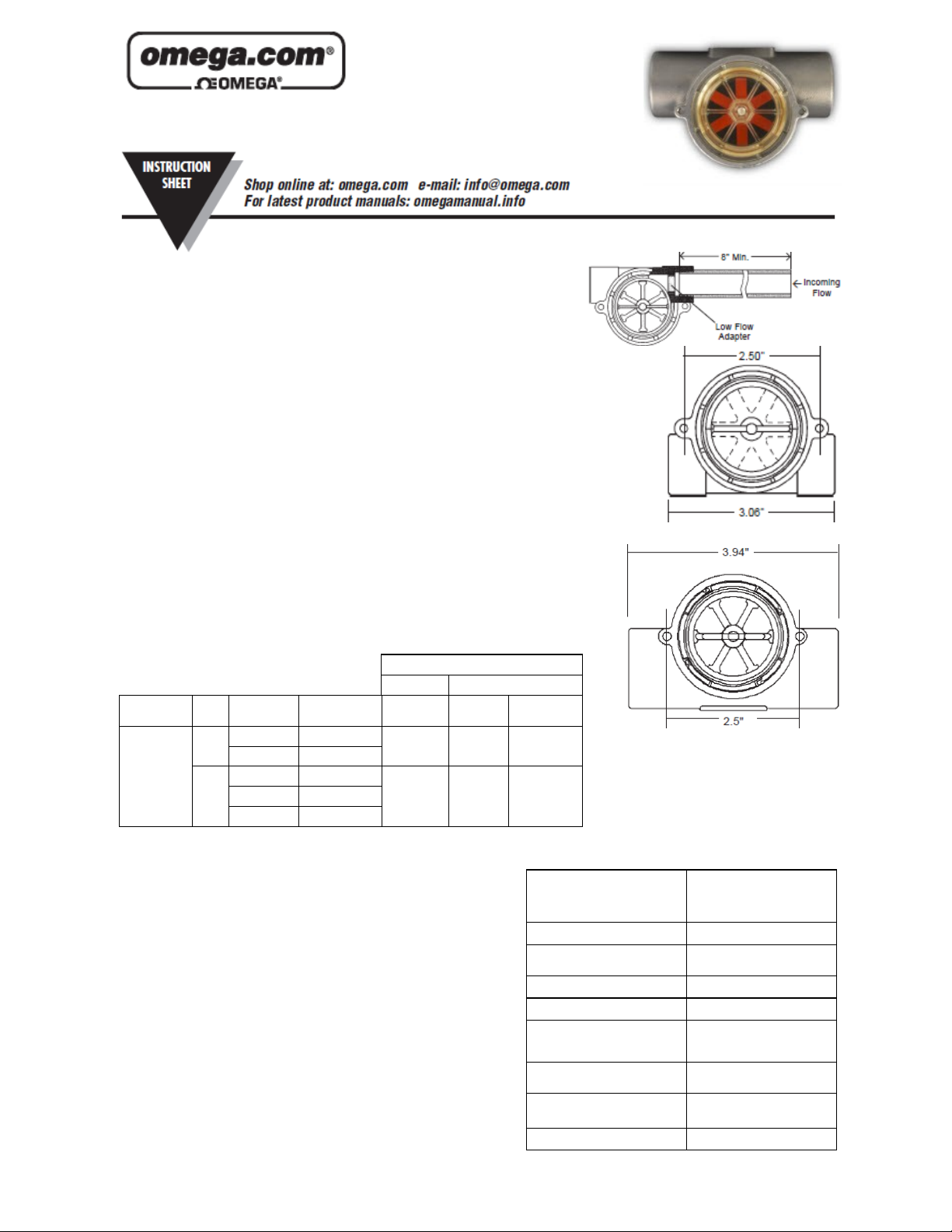
FPR110 Series
Visual Flow Indicator
M-1958/1112
Description:
FP R1 10 un it s m on it or dy na mi c fl ui d flo w. Th e rotor re ac ts to tu rb ul en ce , p ul sation, en tr ai ne d ai r, an d ot her fl ow ab norm al it ie s in duce d in th e flow st re am
by othe r pr oc es s ha rd wa re . Fo r o pt im um p er fo rm ance , in st al l un it s wh er e nominal fl ow co nd it io ns e xist , wi th po rt s lo cated at the to p. In co mi ng f lo w ma y be
placed to ei th er po rt . A min im um of 8” of st ra ig ht pi pe on th e in le t si de is re -
quired.
Installation:
FP R1 10 s er ie s sen so rs c on ne ct t o pi pi ng v ia N PT m at in g th read f or ms . Th e fo ll ow in g
guideli ne s ar e pr ovided to as si st wi th in stal la ti on for a l ea k -f re e s ea l, witho u t da m age to
the un i t : 1. A p p l y pipe th r e a d se a l a n t to m a l e pi p e t h r e a d s . 2.T h r e a d un i t on t o male pi p e
thread un t i l han d - t i g h t . 3. Ti g h t e n pip e 1 to 1- 1 / 2 ad d i t i o n a l t u r n s . 4. I f im pro p e r se a l r e sults , co n t i n u e tu r ning pi p e in t o u nit in 1/ 4 tu r n in c r e m e n t s . Do not ex c e e d on e addit i o n a l
turn. Rec o m m e n d e d P ipe S e a l a n t : P F A T h r e a d T a p e .
Panel Mounting:
An y FP R 1 1 0 s e r i e s s e ns o r m a y b e p a n el m o u n t e d u s i n g ho l e s i n t e g r a t e d into t h e b o d i e s .
PLA S T I C B O D I E S : T w o ( 2 ) mo u n t i n g e a rs a r e p r o v id e d a t the b o d y c e n te r l i n e t o rec e i v e # 8
self - t a p p i n g sc r e w s . N O T E : A N S I T Ty p e 2 3 s e l f -ta p p i n g sc r e w s are re com m e n d e d . T h e y
ma y be r e p l a c e d with sta n d a r d m achine s c r e w s i f r e i n s t al l a t i o n s h o u l d b e req u i r e d .
BRA S S B O D I E S : Two m o u n t i n g h o l e s a r e p r o v i d e d o n t h e bo d y c e n t e r l i n e , as s h o w n .
#8 32UN C - 2 B s c r e ws ar e r e q u i r e d f o r moun t i n g .
Filtration and Cleanin g :
150 m i c r o n fi l t r a t i o n is r e c o m me n d e d . H owev e r , s houl d f orei g n p a r t i cles e n ter t h e
FP R1 1 0 se n s o r, ac c u m u l a t i o n is ea s i l y cl e a r e d by rem o v i n g th e le n s fr o m t h e bo d y .
The l e n s i s r e m o v e d b y t u r n i n g i t s center r i b 4 5 ° c o u nter -cl o c k w i s e a n d t hen p u l l i n g i t
out. T o r e i n s t a l l t h e l e n s , si m p l y r e v e r s e the p r o c e s s . Pres s u r e m u st b e r e l i e v e d from
the s ys t e m p r i o r t o s ens o r c l e a n -o u t .
Port
Body Material
Polypropylene
Brass
Part Number
Size
NPT Threads
FPR111 FPR111-BSP
.25”
.50” FPR112 FPR112-BSP 4.0 - 20.0 1.5 - 12.0 151832
FPR113 FPR113-BSP
.25”
FPR114 FPR114-BSP
.50”
.75” FPR115 FPR115-BSP 5.0 - 30.0 N/A N/A
Part Number
BSPP Threads
Flow Range—GPM
Standard Low Flow
Range Range
0.5 - 5.0 0.1 - 1.0 152147
0.5 - 5.0 0.1 - 1.0 152147
4.0 - 20.0 1.5 - 12.0 133743
Adapter Part
Number
.
.25”, .50” Plastic and Brass Bodies*
.75” Brass Bodies*
*BSPP units are 4.95” wide.
Important Points!
Product must be maintained and installed in strict accordance with the National
Electrical Code and Omega product catalog and instruction bulletin. Failure to
observe this warning could result in serious injuries or damages.
An appropriate explosion-proof enclosure or intrinsically safe interface device
must be used for hazardous area applications involving such things as (but not
limited to) ignitable mixtures, combustible dust and flammable materials.
Pressure and temperature limitations shown on individual catalog pages and
drawings for the specified flow switches must not be exceeded. These pressures and temperatures take into consideration possible system surge pressures/temperatures and their frequencies.
Selection of materials for compatibility with the media is critical to the life and
operation of Omega flow switches. Take care in the proper selection of materials of construction; particularly wetted materials.
Life expectancy of switch contacts varies with applications.
Ambient temperature changes do affect switch set points, since the specific
gravity of a liquid can vary with temperature.
Flow switches have been designed to resist shock and vibration; however,
shock and vibration should be minimized.
Liquid media containing particulate and/or debris should be filtered to ensure
proper operation of Omega products.
Electrical entries and mounting points may require liquid/vapor sealing if located
in an enclosed tank.
Flow switches must not be field repaired.
Physical damaged sustained by the product may render it unserviceable.
Specifications
Wetted Materials
Body
Rotor Pin
Rotor
Lens
O-Ring
Operating Pressure, Max.
Brass Body
Polypropylene Body
Operating Temperature, Max.
Brass Body
Polypropylene Body
Stainless Steel, Brass or Polypropylene (Hydrolytically Stable,
Glass-Reinforced*
Ceramic
High Visibility Orange Molded
Nylon or PFA/PPS
Polysulfone
Buna or FKM
200 psig @ 70°F/80 psig @ 212°
F
100 psig @ 70°F/40 psig @ 212°
F
212°F (100.0°C)
212°F (100.0°C)
Page 2
159197 rev C
 Loading...