

Page 1

Chapter Page
Table of
1 Introduction 1
1.1 Introduction 1
1.2 Front Panel Description 2
1.3 Rear Panel Description 3
2 Installation and Operation 4
2.1 Mounting Instructions 4
2.2 Power Connections 5
2.3 Input Connections 6
2.4 Standard Output Connections 7
2.5 Relay Output Connections 8
2.6 Verifying Analog Outputs 9
2.7 Analog Output Connections 10
3 System Configuration 10
3.1 Introduction 10
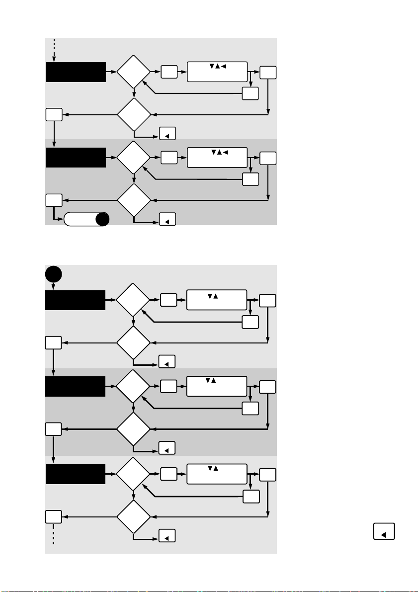
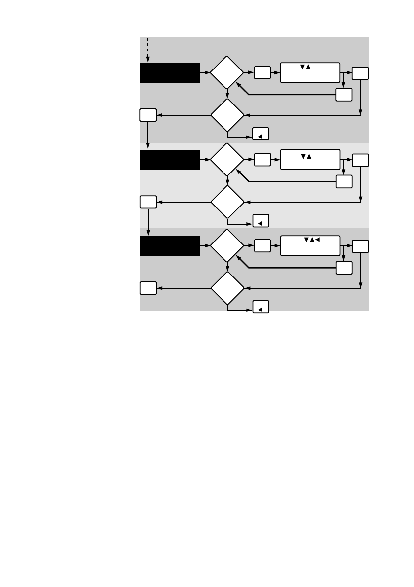
3.2 Calibration Menu, Frequency Inputs 12
3.3 Calibration Menu, Analog Inputs 12
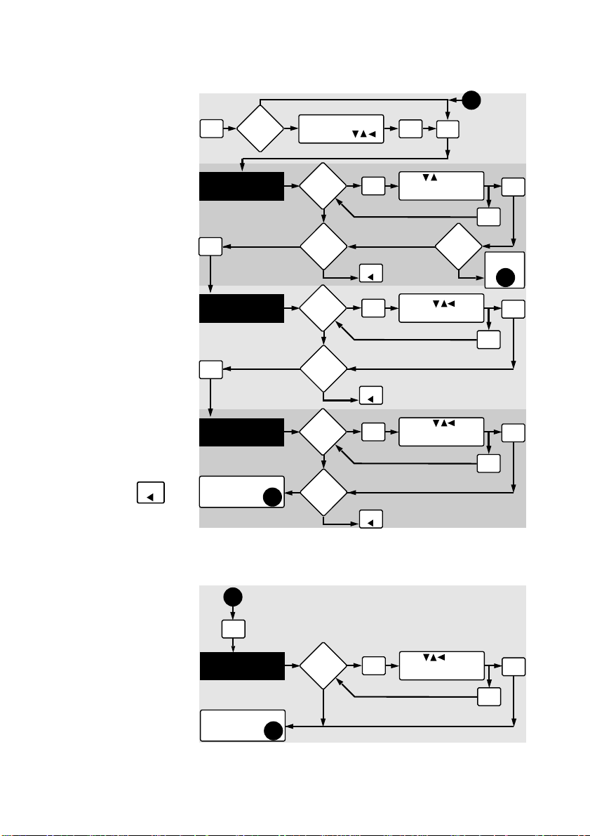
3.4 2-Relay Operations 15
3.5 Calibration Menu, 2-Relay 16
3.6 Calibration Menu, Analog Outputs 17
3.7 View-Only Menus 18
Contents
4 Technical Support 19
4.1 Accessing Internal Options 19
4.2 AC Power Configurations 19
4.3 Installing Input/Output Options 20
4.4 Option Cards and Accessories 21
4.5 Input Card Configuration 22
4.6 Output Card Configuration 23
4.7 Troubleshooting 23
Specifications 24
Warranty 27
Page 2
Important safety information
Danger: Avoid electric shock. Do not connect
power when the instrument cover is partially or
completely removed.
Unpacking and Inspection
Your flow controller package includes the
following items:
• OMEGA FPM-9010A Flow Controller
• Two stainless steel mounting brackets
• Mounting Instructions w/self-adhesive
template
• Panel gasket
Page 3

1.1 Introduction
Your new OMEGA FPM-9010A Flow Controller
has been specifically designed for liquid flow rate
measurement in process pipes. The controller's
compact 1/4 DIN enclosure (front) is NEMA
4X/IP65 rated and ideal for installing into
instrumentation panels with limited space.
Modular "plug-in" input/output option cards allow
you to customize your flow controller to your flow
system's requirements. The controller's unique
"slide-out" chassis design makes option installation
fast and simple. Smart self-configuring
microprocessor based circuitry automatically
inventories installed options during power-up,
allowing you to upgrade your system in seconds
without the need for additional equipment.
The unit's front panel features a highly visible
4.5- digit (seven segment) and 8-digit
(alpha-numeric) liquid crystal display with
adjustable contrast. Active flow rate,
accumulation, and alarm relay information is
quickly accessed at a glance. During calibration
the user is prompted with clear step-by-step
instructions on the unit's front panel display.
The OMEGA FPM-9010A Flow Controller also
accepts other analog inputs, such as
4 to 20 mA or 0 to 5 VDC, etc.
Chapter 1
Introduction
The technical data given in
this publication is for general
information purposes only. It
implies no warranty of any
kind.
1
Page 4
1
2
3
4
5
6
Item Function
1. Relay An-
nunciators:
Indicate activation status of optional output "alarm" relays 1 & 2
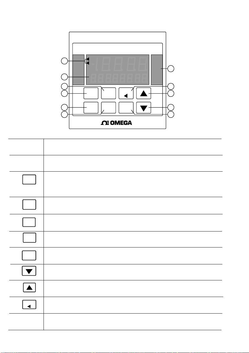
1.2 Front Panel Description
FLOW CONTROLLER
RLY 1
RLY 2
ENTER MOD
CAL RELAY OUTPUT
FLOW
®
GPM
11
Item 11:
Remove front bezel
10
to change unit tags
9
under clear overlay
window. The unit
8
tags are attached
to the rear cover
7
of the manual.
2. LCD
Display:
3.
MOD
.
4
ENTER
5.
CAL
6.
RELAY
7.
OUTPUT
8.
9.
FLOW
10.
11. Unit Tags
Shows flow, calibration, accumulation, and relay activation status information
A) Accesses one of three calibration menus: CAL, RELAY, OUT B) Enables a
calibration parameter for modification C) Restores a calibration parameter to
it's original value during calibration
A) Stores a calibration value into memory after modification B) Used to display
available input/output options during normal operation.
A) Accesses the CAL "view-only" menu B) Used in conjunction with MOD key
to access the main CAL menu
A) Accesses the RELAY "view-only" menu B) Used in conjunction with MOD key
to access the RELAY calibration menu
A) Accesses the OUTPUT "view-only" menu B) Used in conjunction with MOD
key to access the OUTPUT calibration menu
Decreases the value of a selected calibration digit
Increases the value of a selected calibration digit
A) Returns the unit to normal operation mode B) Selects a digit for modification
during calibration
Most engineering units and blanks available for custom applications (included).
User selected and installed for specific applications.
2
Page 5
1 2 3 4 5 6 7 8 9 10 11 12 13 14
15 16 17 18 19 20 21 22 23 24 25 26 27 28
SS CNT
GND
PLS
OUTPUT
ANL2
R+ R-
SERIAL
Tx GND Rx
A in
A+ A-
BLK RED SHLD
SENSOR
L
1
N
AC IN
+ GND
NO C NC
RLY1DC IN
NO C NC
RLY2
R+ R-
ANL1
10
9
8
7
6
12
345
11
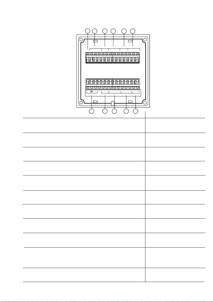
1.3 Rear Panel Description
Note:
Rear terminals
accept 18 to 22 AWG
wire
Function
90 to 132 VAC or 180 to 264 VAC system power
connection
17 to 30 VDC system power connection
Alarm relay #1 (COM, NO, NC) contact set for external
device control (optional)
Alarm relay #2 (COM, NO, NC) contact set for external
device control (optional)
Analog output #1 from option socket #1 (optional)
Flow sensor input connection (frequency)
Analog signal input connection (optional)
Serial outputs (future availability)
Analog output #2 from option socket #2 (optional) 9. ANL2
CNT emits an open collector pulse output for each increment
of totalizer. PLS emits a TTL frequency output in phase with the
sensor input
Item
1.
AC IN
2. DC IN
3. RLY 1
4. RLY 2
5. ANL1
6. Sensor
A in
7.
8. Serial
10. Output
11. SSUnused Terminal
3
Page 6
Chapter 2
Installation
and
Operation
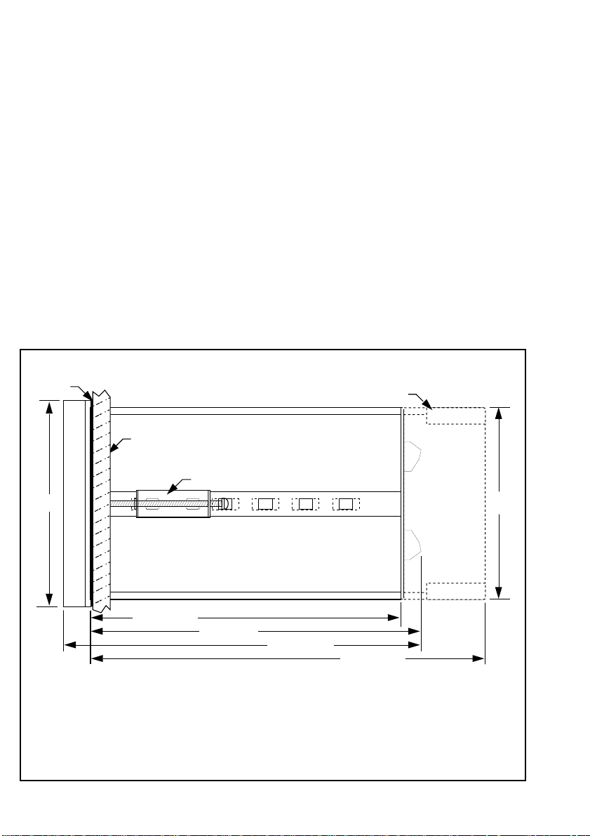
Figure 1
External dimensions
2.1 Mounting Instructions
The OMEGA FPM-9010A Flow Controller's 1/4
DIN enclosure is specifically designed for panel
mounting. Adjustable mounting brackets allow
mounting in panels up to 1 in. (25 mm) thick. An
adhesive template and instructions are included to
insure proper installation.
For outdoor and/or stand alone installations the
splash-proof NEMA 4X/IP65 back cover kit is
recommended (ordered separately).
Panel
Gasket
3.8 in. sq.
96 mm
Mounting Panel
Max. panel thickness = 1 in.(25 mm)
5.7 in.(145 mm)
*Optional PHOR-9RC NEMA 4X/IP65 back cover
Mounting Clamp (included, 2 ea.)
SIDE VIEW
6 in.(152 mm)
6.5 in.(165 mm)
7.2 in.(183 mm)
Panel Cutout Instructions
Recommended panel cutout 90 mm (3.54 in.) square. Maximum panel cutout 92 mm
(3.62 in.) square, DO NOT exceed. Use adhesive backed template (included)
3.5 in.
88 mm
4
Page 7
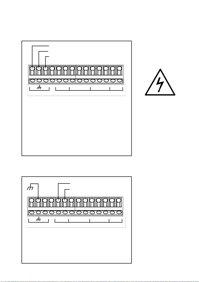
2.2 Power Connections
AC Power Connections
AC Hot
AC Ground*
AC Neutral
15 16 17 18 19 20 21 22 23 24 25 26 27 28
N
L
1
AC IN
+ GND
90 to 132 VAC
OR
180 to 264 VAC
NO C NC
RLY1DC IN
NO C NC
RLY2
R+ R-
Instructions
1. Jumper selectable for 90 to 132 OR 180 to
264 VAC operation. Confirm AC power configuration
before applying power. See section 4.2 pg# 19
2. *A direct or low impedance AC ground (earth
ground) MUST be used for proper operation.
3. To reduce the possibility of noise interference, AC
power lines must be isolated from signal lines.
DC Power Connections
ANL1
Figure 2
AC power wiring
Danger:
shock. Do not connect power
when the instrument cover is
partially or completely
removed.
DC power is recommended
when ground fault interrupt
devices (GFI's) are used.
Avoid electric
*
15 16 17 18 19 20 21 22 23 24 25 26 27 28
L
1
N
AC IN
17 to 30 VDC @ 0.5 A
GND
NO C NC
+ GND
RLY1DC IN
NO C NC
RLY2
R+ R-
ANL1
Note: AC/DC power can be connected simultaneously,
using DC power as an uninterrupted power source.
*A direct or low impedance earth ground MUST be used
for optimum performance.
Figure 3
DC power wiring
5
Page 8
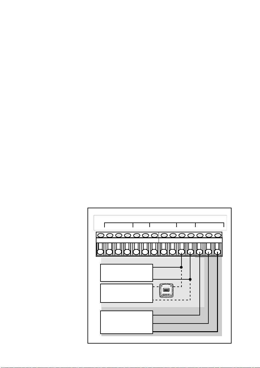
2.3 Input Connections
Four input sources are accepted:
Note:
for a listing of available input
cards.
See section 4.4
Figure 4
Input Wiring
A. Non-isolated Frequency Inputs
Frequency (non-iso) card: Accepts non-isolated,
0 to 10 kHz @ 0.2 Vp-p minimum sine or square
wave signal inputs. This card requires dip switch
configuration prior to operation.
B. Isolated Frequency Inputs
Frequency (iso) card: Accepts isolated, 0 to
10 kHz @ 0.5 Vp-p minimum sine or square wave
signal inputs. No configuration required.
C. Analog Inputs
Two analog input cards are offered:
• Analog (iso) current, 4 to 20/0 to 20 mA
• Analog (iso) voltage, 0 to 5/0 to 10 VDC
Input ranges are software selectable, requiring no
internal configuration.
SS CNT
OUTPUT
GND
PLS
ANL2
R+ R-
SERIAL
Tx GND Rx
A in
A+ A-
SENSOR
BLK RED SHLD
To reduce the possibility of
noise interference, separate
input lines from AC power
lines.
6
1 2 3 4 5 6 7 8 9 10 11 12 13 14
Analog Input:
Current or Voltage
C
External DC
Power Supply
OR
A
Frequency Input:
for OMEGA sensors
&
and others
R+
R-
+-
+
-
BLACK
RED
SHIELD
OMEGA
FP85A
B
Page 9
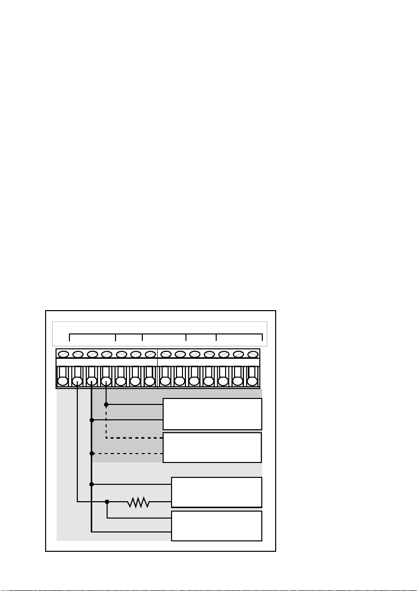
2.4 Standard Output Connections
Standard Outputs
An open collector counter pulse output (CNT) and
a sensor pulse output (PLS) are included with your
unit.
The counter pulse output (synchronous w/totalizer)
emits an open collector 150 ms pulse with a
maximum current sinking capacity of 50 mA @
30 VDC, and is ideal for driving an external
counter or accumulator. An external DC power
supply and current limiting resistor are required
for operation.
The sensor pulse output (PLS) emits a standard TTL
frequency output in phase with the sensor input
and can be used to drive OMEGA instruments
(except OMEGA FPM-5800) and other TTL
compatible devices.
SS CNT
OUTPUT
GND
PLS
ANL2
R+ R-
SERIAL
Tx GND Rx
A in
A+ A-
SENSOR
BLK RED SHLD
Figure 5
Sensor pulse output (PLS)/
counter output (CNT)
wiring
1 2 3 4 5 6 7 8 9 10 11 12 13 14
Red (2)
OMEGA
Indicator or
OR
600Ω @ >1.5 W
Shld (3)
Input
Gnd
Controller
TTL
Compatible
Device
Gnd
5 to 30 VDC
Power Supply
+
IN
External counter
or accumulator
Gnd
To reduce the possibility of
noise interference, separate
output lines from AC power
lines.
7
Page 10
15 16 17 18 19 20 21 22 23 24 25 26 27 28
L1
AC IN
+ GND
NO C NC
RLY1DC IN
NO C NC
RLY2
R+ R-
ANL1
Device A
Device B
External
AC/DC
Power
Source
+
-
+
+
-
-
N
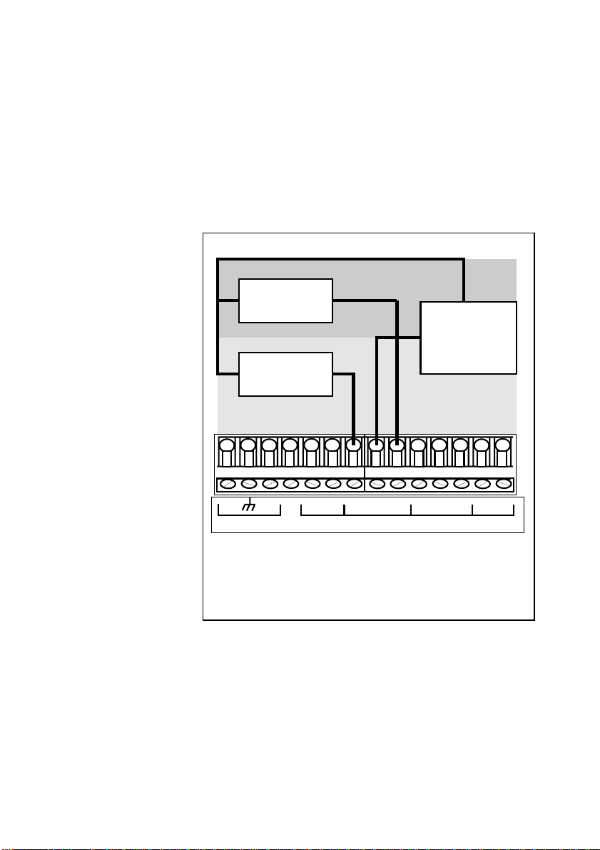
Figure 6
2-Relay wiring
Device A is powered during
normal operation. Power is
discontinued when relay is
energized. Device B is not
powered during normal
operation. Power is applied
after relay is energized.
2.5 Relay Output Connections
The 2-Relay option provides two relays for external
device control. Each relay's contacts are rated for
5 A maximum. Both NO and NC contacts may
be used individually or simultaneously as shown.
To reduce the possibility of
noise interference, separate
AC relay lines from input/
output lines.
Note:
5 A @ 30 VDC maximum resistive load.
Relay contacts are rated as 5 A @ 250 VAC or
8
Page 11
2.6 Verifying Analog Outputs
Installed analog output options can be configured
to either of the unit's rear analog output terminals:
ANL1 or ANL2. Configuration is determined by
which sockets the options are installed. Options
installed in option socket #1 are configured to the
rear ANL1 terminals, options installed in socket #2
are configured to the rear ANL2 terminals (see
section 4.3).
Prior to connection, determine which options are
configured to terminals ANL1 and ANL2 as
follows:
1. Apply power to unit.
ENTER
2. Press:
individually prompted on the display.
; available input/output options are
3. Record option configurations for ANL1 and
ANL2 in the spaces provided. This information is
necessary for wiring analog outputs in the next
section.
ANL1=
(i.e. 4 to 20 mA)
ANL2=
(i.e. N/A)
Danger:
shock. Do not connect power
when the instrument cover is
partially or completely
removed.
Avoid electric
Option Record
Note:
N/A for unavailable options.
The unit displays
9
Page 12
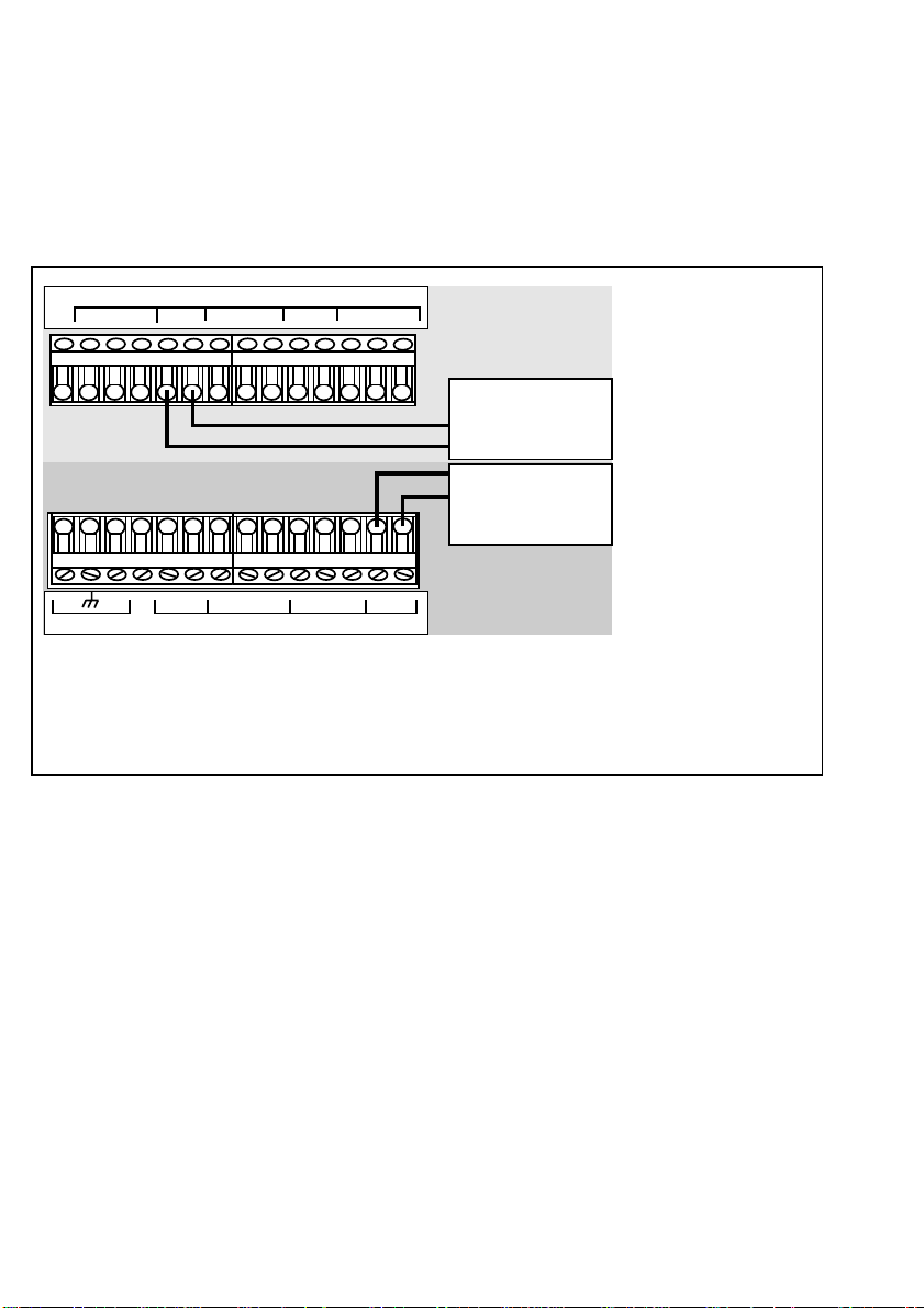
Figure 7
Analog output wiring
2.7 Analog Output Connections
0 to 20/4 to 20 mA isolated or non-isolated
output as well as 0 to 5/0 to 10 VDC isolated or
non-isolated outputs are available. See section
4.4 for a list of available output cards.
GND
N
ANL2 SERIAL
R+ R-
PLS
+ GND
Tx GND Rx A+ A-
NO C NC
RLY1DC IN
A in SENSOR
BLK RED SHLD
NO C NC
RLY2
R+ R-
ANL1
Analog Ouput #2
(i.e. 0 to 5 VDC)
-
etc.
+
+
Analog Output #1
-
(i.e. 4 to 20 mA*)
etc.
*The 4 to 20 mA
option is jumper
configurable for
0 to 20 mA
operation. Refer to
section 4.6
The maximum loop impedance for the 4 to 20 mA/0 to 20 mA output is 425 Ω.
OUTPUT
SS CNT
1 2 3 4 5 6 7 8 9 10 11 12 13 14
15 16 17 18 19 20 21 22 23 24 25 26 27 28
L
1
AC IN
Note:
The minimum load impedance for the 0 to 5 V/0 to 10 V output is 1 kΩ (1000 Ω). To
reduce the possibility of noise interference, separate output lines from AC power/relay lines.
Chapter 3
3.1 Introduction
All the functions which can be modified are
contained in three menus:
System
Configuration
10
The CAL (calibrate) menu contains those functions
which pertain to the input signal and how it is
interpreted by the instrument (i.e. K-factor, totalizer
reset). The CAL menu also provides access to the
security code and display contrast features.
The RELAY menu contains all the functions necessary to control any output relays, such as relay
Page 13
setpoint, hysteresis etc.
The OUTPUT menu provides access to the functions
which define and control all analog output signals,
i.e. 4 to 20 mA, 0 to 5 VDC etc.
CAL Menu
CAL
(frequency)
• K-factor
• K-factor decimal
• Upper display timebase
• Totalizer reset
• Totalizer multiplier
• Display averaging
RELAY Menu
(LO/HI)
• Relay 1 LO/HI
• Relay 1 setpoint
• Relay 1 hysteresis
• Relay 2 LO/HI
• Relay 2 setpoint
• Relay 2 hysteresis
RELAY
• Display decimal
• Contrast adjust
• Security code
(Pulse)
• Relay 1 Pulse
• Relay 1 pulse flow
(Analog)
• Range selection
• Minimum flow rate
• Maximum flow rate
unit setting
• Relay 2 Pulse
• Relay 2 pulse flow
unit setting
• Totalizer reset
• Totalizer multiplier
• Display averaging
• Display decimal
• Contrast adjust
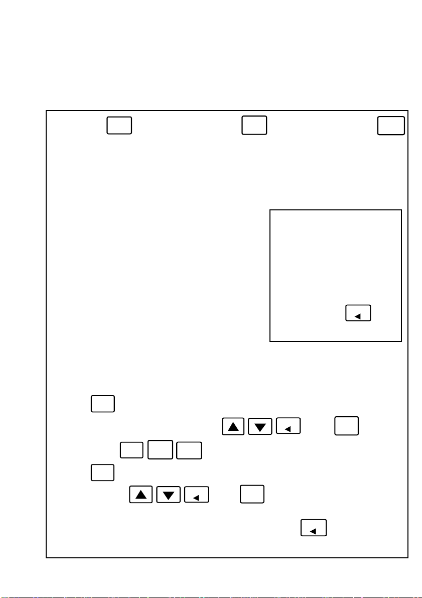
All menus operate using a standard sequence:
1. Press:
2. Enter security code (when active) using:
MOD
to enable calibration sequence.
OUTPUT Menu
OUTPUT
• Minimum flow rate
• Maximum flow rate
• Low output adjust
• High output adjust
Note: A security function is
provided which allows the user
to "lock out" the calibration
menus, restricting access to
calibration settings. See Figure
14 .
All menus are loop type menus
which repeat until
FLOW
is
pressed.
FLOW
; press:
ENTER
3. Select menu:
4. Press:
MOD
to enable modifying item.
5. Alter item using:
CAL
OUTPUT
; press menu key to select item.
FLOW
; press:
ENTER
to save entry.
RELAY
6. Press corresponding menu key to advance to next menu item.
7. Repeat steps 4-6 for each menu item. Exit menu by pressing:
FLOW
11
Page 14
MOD
Security
Code?
Yes
Unlock security
code using:
ENTER
No
CAL
ENTER
Modify?
No
Yes
Select
next
item?
Yes
CAL
FLOW
Press to select
operation range,
(4-20 or 0-20 mA)
MOD
Normal operation
4
mA= 0 or 4
Recall original value
MOD
No
Legend
MOD
Security
Code?
Yes
Unlock security
code using:
ENTER
Modify?
No
Yes
Select
next
item?
Yes
FLOW
Press to
set K-factor from
.0001 to 19999.
19999
K-FACTOR
MOD
Normal operation
ENTER
Recall original value
MOD
No
CAL
No
CAL
Decimal set
in next step
ENTER
Modify?
No
Yes
Select
next
item?
Yes
CAL
FLOW
Press to
select decimal
location, 0-4 plcs.
18888
K-f DP=0
MOD
Normal operation
Recall original value
MOD
No
ENTER
Modify?
No
Yes
Select
next
item?
Yes
CAL
FLOW
Press to select
upper display
timebase (1-4)
2
TIMEBASE
MOD
Normal operation
Recall original value
MOD
No
Go to
A
See Table 1
= Press Keypad
= Decision
Block
= FPM-9010A
Display
= Calibration
procedure
18888
XXXXXXXX
K-factor Setting
"1" is displayed only when
previously selected.
"1" flashes when deselected.
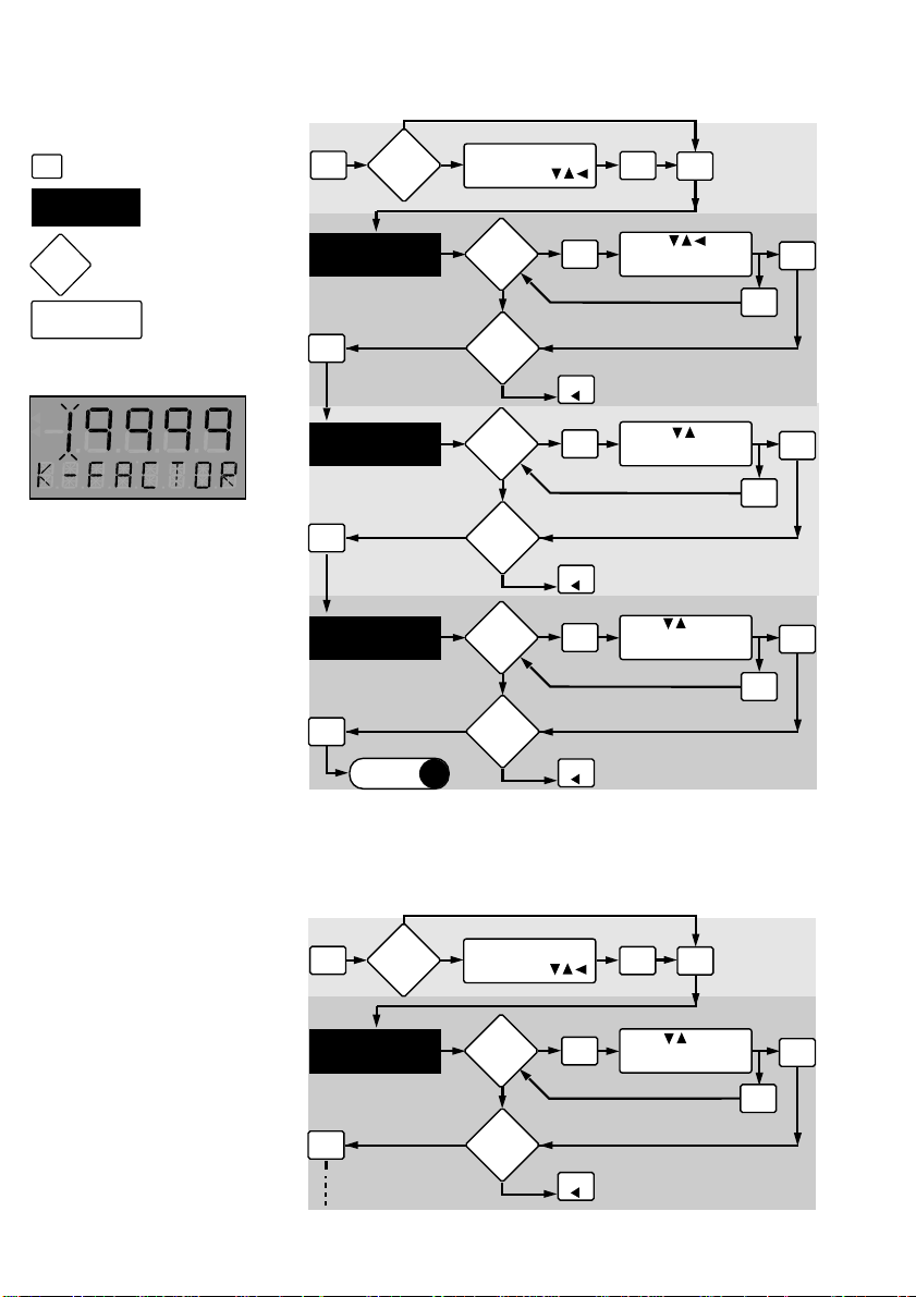
3.2 Calibration Menu, Frequency Inputs
Table 1
Select upper display timebase:
1= flow displayed in seconds
2= flow displayed in minutes
3= flow displayed in hours
4= flow displayed in days
Note: Accumulator not
affected by timebase.
4 to 20 mA option illustrated
Note:
The unit's software
recognizes which input card/
configuration is inserted,
therefore displaying the
corresponding calibration
value.
12
3.3 Calibration Menu, Analog Inputs
Page 15
18888
4mA IS
CAL
Yes
Modify?
No
Select
next
item?
No
Yes
MOD
FLOW
Press to
enter minimum
flow rate
Recall original value
Normal operation
ENTER
MOD
18888
20mA IS
CAL
Go to
A
TOTL
XXXXXXXX
CAL
1
TOTL X
CAL
Yes
No
No
No
No
No
No
Yes
Yes
MOD
FLOW
MOD
FLOW
MOD
FLOW
Modify?
Select
Yes
next
item?
A
Modify?
Select
Yes
next
item?
Modify?
Select
Yes
next
item?
Press to
enter maximum
flow rate
Recall original value
Normal operation
Press to reset
totalizer to zero
Recall original value
Normal operation
Press to select
multiplier; X0.1,X1,
X10,X100,X1000
Recall original value
Normal operation
ENTER
MOD
ENTER
MOD
ENTER
MOD
02
FLO AVRG
CAL
Continued
Yes
Modify?
Select
next
item?
No
No
Yes
MOD
FLOW
Press to select
averaging time,
2-10 seconds
Recall original value
Normal operation
MOD
ENTER
Exiting Menu
Menu will repeat until
is pressed.
FLOW
13
Page 16
ENTER
Modify?
No
Yes
Select
next
item?
Yes
CAL
FLOW
Press to select
best contrast
18888
CONTRAST
MOD
Normal operation
ENTER
Modify?
No
Yes
Repeat
menu?
Yes
CAL
FLOW
Press to
select personal
security code
0000
SEC CODE
MOD
Normal operation
No
Recall original value
MOD
Recall original value
MOD
No
ENTER
Modify?
No
Yes
Select
next
item?
Yes
CAL
FLOW
Press to select
display decimal,
0-4 places
- - - . - -
FLO DP=2
MOD
Normal operation
Recall original value
MOD
No
14
Page 17
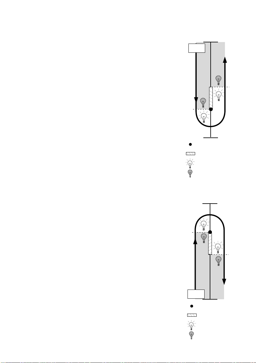
3.4 2-Relay Operations
The 2-Relay option allows you to configure
individual setpoints, LO or HI operation, and
hysteresis values for two independent on/off
relays.
• Relay Setpoints: Setpoints represent the flow
rate at which each relay is energized.
• Relay Hysteresis: Hysteresis values directly
effect the LO and HI relay modes, specifying how
far the flow will rise above (LO Relay Mode) or fall
below (HI Relay Mode) each relay's setpoint prior
to de-energizing the relay. The main purpose for
hysteresis is to eliminate relay "chatter", caused by
a flow hovering around a relay's setpoint.
Hys-teresis values are programmed in direct flow
units and must be less than the corresponding relay
setpoint. Hysteresis only applies when exiting an
alarm condition.
Figure 8
LO relay operation mode
Flow
= LO setpoint
= Hysteresis
= Relay energized
= Relay de-energized
• LO Relay Operation: In LO operation, the relay
is energized when the flow drops below the
set-point, and is de-energized when the flow rises
above the setpoint plus hysteresis. See Figure 8.
• HI Relay Operation: In HI operation, the relay
is energized when the flow rises above the
setpoint and is de-energized when the flow falls
be-low the setpoint plus hysteresis. See Figure 9.
• Pulse Relay Setting: Setting relay 1 or 2 to the
Pulse operation mode means the relay will be
cycled (energized) for a 150 ms period each time
a user specified quantity is measured.
Figure 9
HI relay operation mode
Flow
= HI setpoint
= Hysteresis
= Relay energized
= Relay de-energized
15
Page 18
Relay 2 LO, HIGH,
or PULSE, go to:
A
MOD
Security
Code?
Yes
Unlock security
code using:
Select
next
item?
Yes
RELAY
FLOW
Normal operation
ENTER
Recall original value
Modify?
No
Yes
Press to select
relay operation mode
LO, HIGH, or PULSE
LO
RLY1 IS
MOD
MOD
No
Modify?
No
Yes
Select
next
item?
Yes
RELAY
FLOW
Press to
set relay setpoint
0100
SET RLY1
MOD
Normal operation
Recall original value
MOD
Modify?
No
Yes
Select
next
item?
Yes
FLOW
Press to
select relay
hysteresis
0020
SET HYS1
MOD
Normal operation
Recall original value
MOD
No
PULSE
Mode
?
Yes
Go to
ENTER
Modify?
No
Yes
Press to set
pulse units (0.1 to
9999999.9)
rLY 1
XXXXXXX.X
MOD
MOD
Recall original value
RELAY
No
No
No
A
RELAY
B
Relay 2 LO, HIGH,
or PULSE, go to:
A
B
ENTER
ENTER
ENTER
3.5 Calibration Menu, 2-Relay
Note:
position set by CAL menu
K-factor
Displayed decimal
Exiting Menu
Menu will repeat until
pressed.
FLOW
is
Note:
Relay cannot exceed
4 pulses per second.
16
Page 19
1 2 3 4 5 6 7 8 9 10 11 12 13 14
15 16 17 18 19 20 21 22 23 24 25 26 27 28
SS CNT
GND
PLS
OUTPUT
ANL2
R+ R-
SERIAL
Tx GND Rx
A in
A+ A-
BLK RED SHLD
SENSOR
L1
N
AC IN
+ GND
NO C NC
RLY1DC IN
NO C NC
RLY2
R+ R-
ANL1
R+
R-
R+
R-
AMMETER
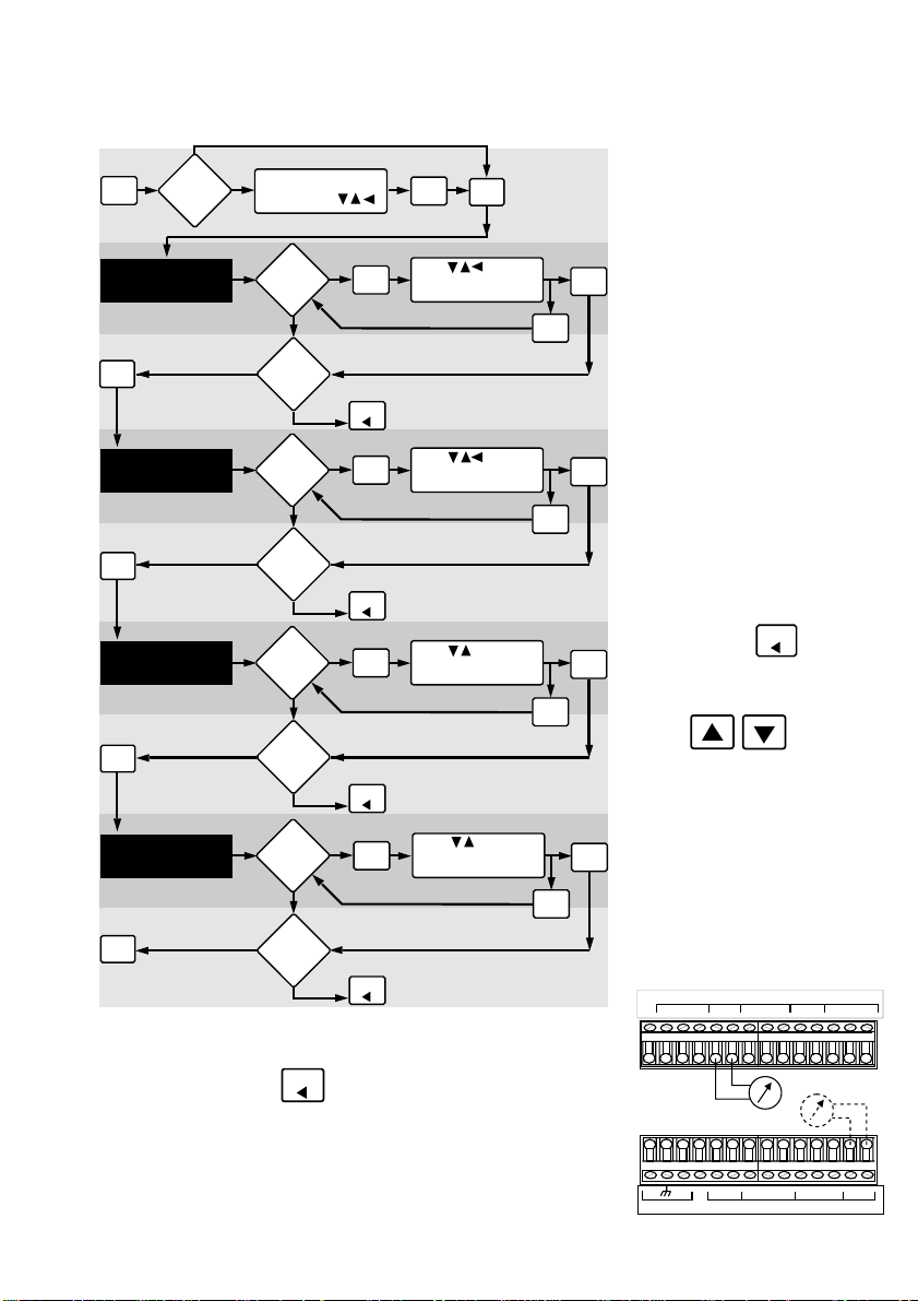
3.6 Calibration Menu, Analog Outputs
No
Security
MOD
OUTPUT
OUTPUT
Ammeter required,
see Figure 10
OUTPUT
Code?
9999
ANL 1 4m
9999
ANL 1 20m
4
ADJUST
Yes
Yes
Yes
Yes
Unlock security
code using:
Yes
Modify?
No
Select
next
item?
No
Yes
Modify?
No
Select
next
item?
No
Yes
Modify?
No
Select
next
item?
No
ENTER
Press to select
MOD
flow rate at 4 mA
output signal
Recall original value
FLOW
Normal operation
Press to select
MOD
flow rate at 20 mA
output signal
Recall original value
FLOW
Normal operation
Press to fine tune
MOD
4 mA output signal.
See note*
Recall original value
FLOW
Normal operation
OUTPUT
MOD
MOD
MOD
4 to 20/0 to 20 mA (iso/
non-iso) options illustrated
ENTER
ENTER
*Note:
ENTER
access the minimum or
Press:
maximum current output signal
Press: to fine tune
the current output signal
FLOW
to quickly
20
ADJUST
Ammeter required,
see Figure 10
OUTPUT
Exiting Menu
Menu will repeat until
Yes
Modify?
No
Repeat
Menu?
FLOW
Yes
MOD
FLOW
No
is pressed.
Press to fine tune
20 mA output signal.
See note*
Recall original value
Normal operation
MOD
ENTER
Figure 10
The min. and max. current
adjustment steps require an
external ammeter for
monitoring the current output.
17
Page 20
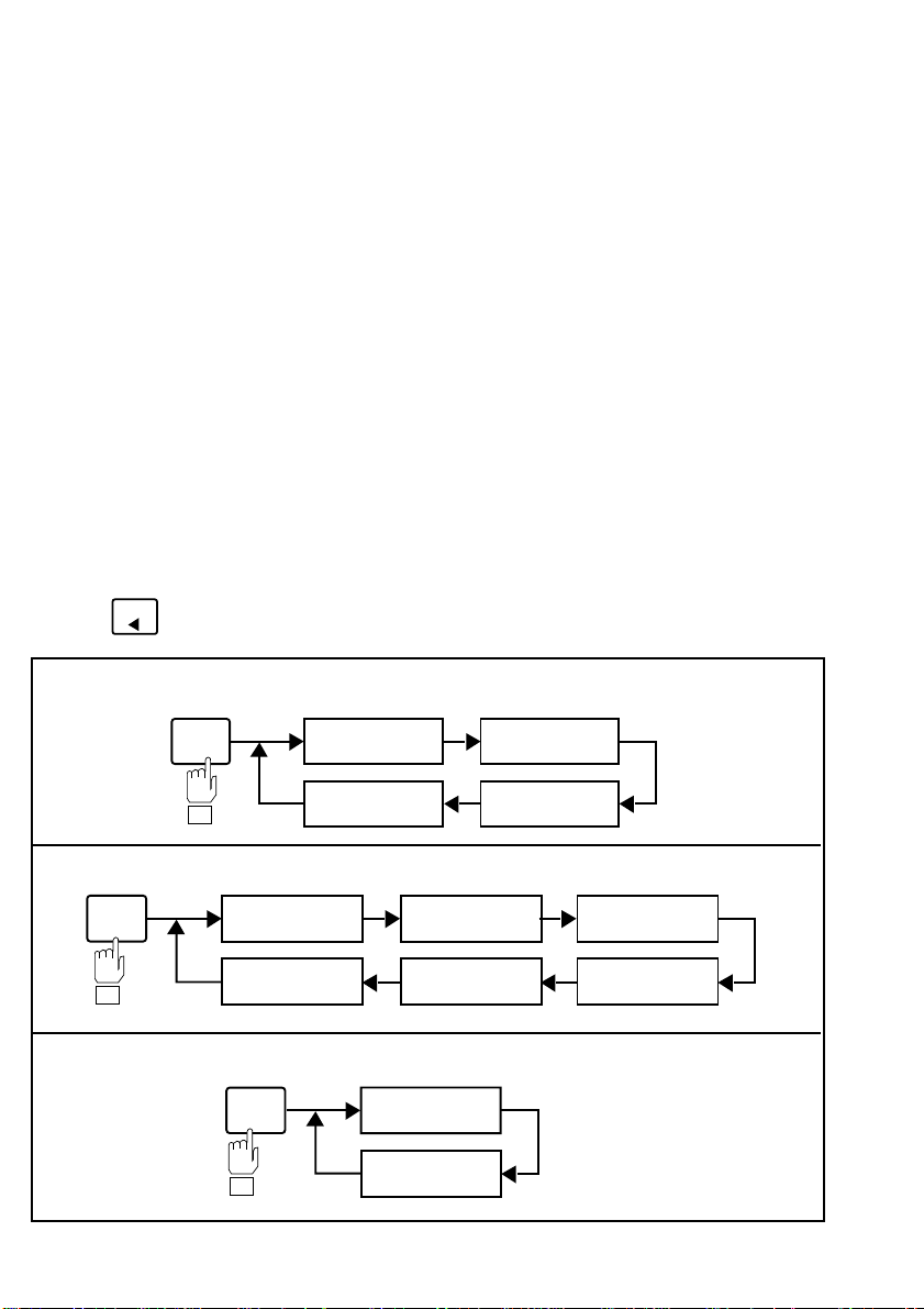
3.7 View-Only Menus
Note:
The view-only menus
are designed for viewing only
and DO NOT permit access
for calibration of any kind.
Menus will vary depending
upon installed options.
Exiting Menus:
only menus at any time by
pressing:
Main (CAL) view-only menu: Frequency (iso/non-iso) input option illustrated
FLOW
Exit view
Three "view-only" menus (CAL, RELAY, and
OUTPUT) are available during normal operation.
Each view only menu provides the operator a
means of browsing through calibration settings
without disturbing system calibration and/or the
flow process. When used in conjunction with the
security feature, the view only menus allow an
operator access to limited calibration information
on the front display, excluding the ability to
change system parameters without the supervisor's
approval and personal security code.
Access each of the three view only menus by
pressing the corresponding menu key. After
entering each of the three view only menus, each
calibration parameter is sequentially displayed on
the main and lower displays by successively
pressing its corresponding menu key as follows:
CAL
Relay view-only menu: 2-Relay LO/HI output option illustrated
RELAY
Output view-only menu: 4 to 20 mA (iso/non-iso) output option illustrated
Relay 1 LO, HI,
or Pulse
Relay 2
hysteresis
OUTPUT
K-factor
Flow display
decimal pt.
Relay 1
setpoint
Relay 2
setpoint
Flow rate setting
for 4 mA output
Flow rate setting
for 20 mA output
Totalizer
Resolution
Flow display
averaging
Relay 1
hysteresis
Relay 2 LO, HI,
or Pulse
18
Page 21
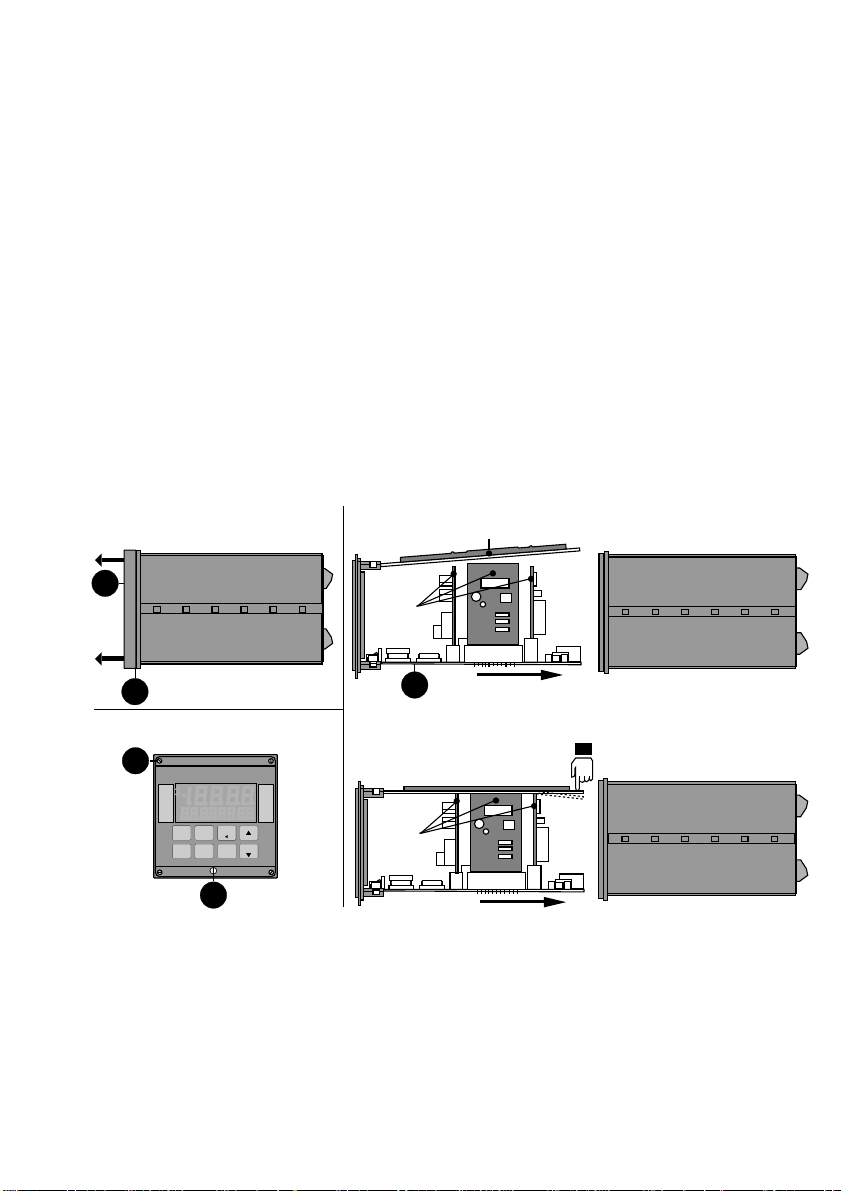
4.1 Accessing Internal Options
1. Remove bezel (1) by placing a coin in the
notch (2), twist coin to remove the bezel from the
instrument casing. See Figure 11
Chapter 4
Technical
2. Loosen the four front bracket screws (3), then
loosen the center "jack-screw" (4). See Figure 12
3. Slide the electronics assembly (5) from the
instrument casing. See Figure 13
4. Lift upper retainer with adhesive gasket to
install/remove plug-in cards. Be sure plug-in cards
are properly seated in slots before reassembling
instrument. See Figure 13
Figure 11
Figure 13
card retainer
1
Input/
output
cards
2
Figure 12
3
RLY 1
RLY 2
RLY 3
RLY 4
Front
Panel
Side View
4
5
Push down on card retainer
to slide the chassis back
into the case.
Input/
output
cards
Support
4.2 AC Power Configurations
Two AC power options are possible; 90 to 132
VAC, or 180 to 264 VAC. Each power option is
selectable via internal jumpers on the main pc
board. See Figure 14
Warning:
configuration before applying
power to unit.
Check AC
19
Page 22
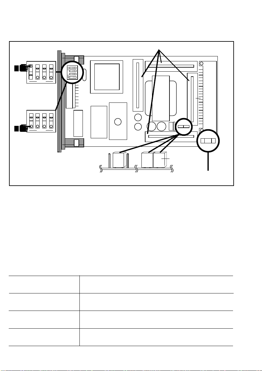
Figure 14
Main PC Board
Security Feature
123
OPEN
Enable the security
feature by setting
positon #1 "closed"
123
OPEN
Disable the security
feature by setting
positon #1 "open"
Option Sockets
4
4
1
2
OPEN
3
4
INPUT CARD
OUTPUT CARD #1
OUTPUT CARD #2
Blue
Jumpers
OUTPUT CARD #3
180 to 264 VAC
operation
90 to 132 VAC
operation
OR
Fuse, 1/4 A @
250 VAC (fast blow)
4.3 Installing Input/Output Options
Input/output option cards are "keyed" for proper
insertion into four sockets. Sockets are located on
the unit's main PC board and are clearly marked.
See Figure 14 and table below:
Socket Labeled Compatible Options
Input Card Dedicated for input cards
Output Card #1 Accepts all analog output cards
Output Card #2 Accepts all analog output cards
Output Card #3 Dedicated for the 2-Relay output card.
20
Page 23
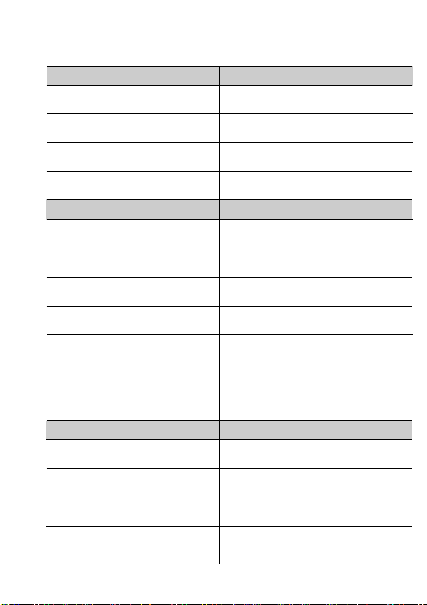
4.4 Option Cards and Accessories
Part Number Input Cards
FPM-9011A (requires configuration) Frequency Input (non-isolated)
See section 4.5
FPM-9012A (configuration not Frequency Input (isolated)
required)
FPM-9013A 4 to 20/0 to 20 mA input
(isolated)
FPM-9014A 0 to 5/0 to 10 VDC input
(isolated)
Part Number Output Cards
PHOR-90-MA-N (requires configuration) 4 to 20/0 to 20 mA
See section 4.6 (non-isolated)
PHOR-90-5V-N 0 to 5 VDC (non-isolated)
PHOR-90-10V-N 0 to 10 VDC (non-isolated)
PHOR-90-MA-I (requires configuration) 4 to 20/0 to 20 mA (isolated)
See section 4.6
PHOR-90-5V-I 0 to 5 VDC (isolated)
PHOR-90-10V-I 0 to 10 VDC (isolated)
PHOR-90-R2 2-Relay card
Part Number Accessories
PHOR-9AP OMEGA mounting
adapter plate
PHOR-9RC NEMA 4X/IP65 back cover
3-9010.650 Assorted engineering labels
3-9000.392 Conduit connector kit for
NEMA 4X back cover
(includes 3 connectors)
21
Page 24
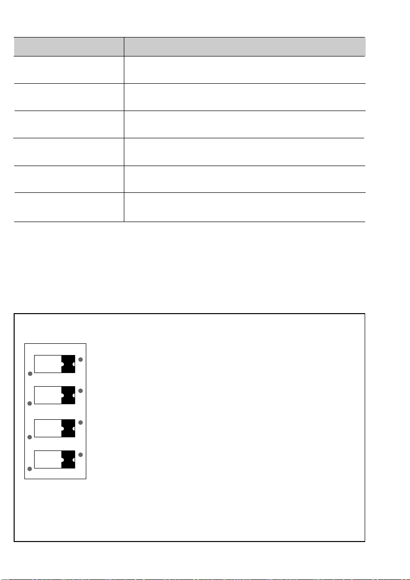
Part Number Spare Parts
3-9000.525-1 Front bezel
3-9000.575 Panel mounting gasket
3-9000.560 Mounting Clamp
2400-0404 Front cover screws (4 each)
3-9000.570 Front cover gasket
PHOR-9FUSE Fuse, 1/4 A @ 250 VAC (fast blow)
4.5 Input Card Configuration
Figure 15
Frequency (non-iso) input card
dip switch settings
The non-isolated Frequency Input Card requires dip
switch configuration prior to operation. See Figure
15
0 1
Frequency
Input Card
Dip Switch
22
Omega Dip switch settings
Sensor 1234 Function
1
FP-540 1011 5 VDC power to sensor
FP-2502 with pull down resistor
FP-5300, FP-5100 1111* No power to sensor with
234
TTL inputs pulldown resistor
FP-5200 1110 No power to sensor with no
FP-6000 pulldown resistor
FP-5060 Series 1001 5 VDC power to sensor
FP-5070-PV Series with pull up resistor
FP-5600 Series
FP-2540 Series
FMG2550 Series
*Dip switch factory configured for the
OMEGA FP-5300 Series Flow Sensors.
Page 25
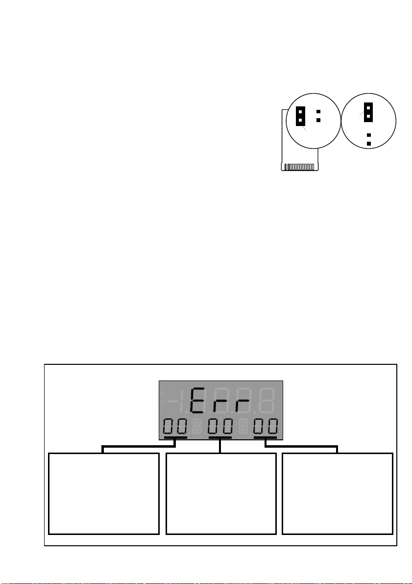
4.6 Output Card Configuration
Isolated version
A
B
Blue
Jumper
Non-isolated
version
A B
Blue
Jumper
Each 4 to 20/0 to 20 mA (iso or non-iso) output
card contains jumper selections for it's operation
range.
• Placing the blue jumper in the "A" position
configures the card for 4 to 20 mA operation.
• Placing the blue jumper in the "B" position
configures the card for 0 to 20 mA operation.
4.7 Troubleshooting
Error codes will be shown on the display after an
abnormal occurrence, such as large amounts of
electromagnetic interference or a large voltage
transient on the AC power line occur.
Displayed error codes represent corrupted setup
data in the internal memory which must be reentered by the operator. See Figure 17.
Figure 16
4 to 20/0 to 20 mA output
cards
Figure 17
Displayed error codes
Front
Display
CAL Menu Error Codes
01: Reset K-factor/low setpoint
02: Reset K-factor/high setpoint
03: Reset Totalizer
04: Reset totalizer multiplier
05: Reset flow averaging
06: Reset flow decimal
07: Reset contrast
08: Reset security code
RELAY Menu Error Codes
01: Reset relay 1 LO, HI or Pulse
02: Reset relay 1 flow/pulse setpoint
03: Reset reley 1 hysteresis
04: Reset relay 2 LO, HI or Pulse
05: Reset relay 2 flow/pulse setpoint
06: Reset relay 2 hysteresis
OUTPUT Menu Error Codes
01: Recalibrate ANL 1 settings
02: Recalibrate ANL 2 settings
23
Page 26

Specifications
Power Requirements
17 to 30 VDC @ 0.5 A max. and/or
90 to 132 VAC @ 50 to 60 Hz or
180 to 264 VAC @ 50 to 60 Hz
Operating Temperature
0 to 55 °C (32 to 130 °F)
Relative Humidity
95% R.H. max., non-condensing
Enclosure
Materials: ABS plastic
Rating: NEMA 4X/IP65 front
NEMA 4X/IP65 rear cover (optional)
Dimensions: 3.5 X 3.5 X 6.0 in./
88 X 88 X 165 mm
Memory Backup
Non-volatile RAM
Liquid Crystal Display
4.5 digits, 12.7 mm (0.5 in.) height (upper)
8 digits, 7.6 mm (0.3 in.) height (lower)
2 alarm annunciators
Accuracy: 0-5 kHz input, 0.05% of reading
24
Display Averaging
Programmable from 2 to 10 seconds
Noise Immunity
Exceeds IEC 801-2, level 3, IEC 801-3, level 2
Input Signal
Frequency (iso or non-iso):
Frequency range: 0 to 10 kHz
K-factor range: .0001 to 19999.
Minimum signal amplitude:
Non-iso freq input: 0.2 Vp-p (continued)
Page 27

Isolated freq input: 0.5 Vp-p
Isolation: 500 VDC to earth ground
Flow Current and Voltage (iso):
Input range: 4 to 20 mA or 0 to 20 mA
0 to 5 VDC or 0 to 10 VDC
Isolation: 500 VDC isolation to earth ground
Output Signals
Sensor Pulse Output
TTL compatible synchronous with sensor input
Max. current sink: 20 mA
Max. current source: 10 mA
Counter Pulse Output
Open collector transistor synchronous with totalizer
Max. current sink: 50 mA @ 30 VDC max.
2-Relay
Outputs: Two SPDT contact outputs: 5 A @ 250
VAC or 30 VDC resistive load max. current
Analog 4 to 20 or 0 to 20 mA
Response time: 2.5 s max. for 100% change
Maximum loop resistance: 425 Ω
Isolation: 500 VDC to earth ground
Accuracy: ±0.5% of full scale
Analog 0 to 5 or 0 to 10 VDC
Response time: 2.5 s max. for 100% change
Maximum loop resistance: 1 kΩ (1000 Ω)
Isolation: 500 VDC to earth ground (optional)
Accuracy: ±0.5% of full scale
25
Page 28

Notes:
26
 Loading...