

Page 1
User’s Guide
Shop online at
omega.com
e-mail: [email protected]
For latest product manuals:
www.omegamanual.info
SM
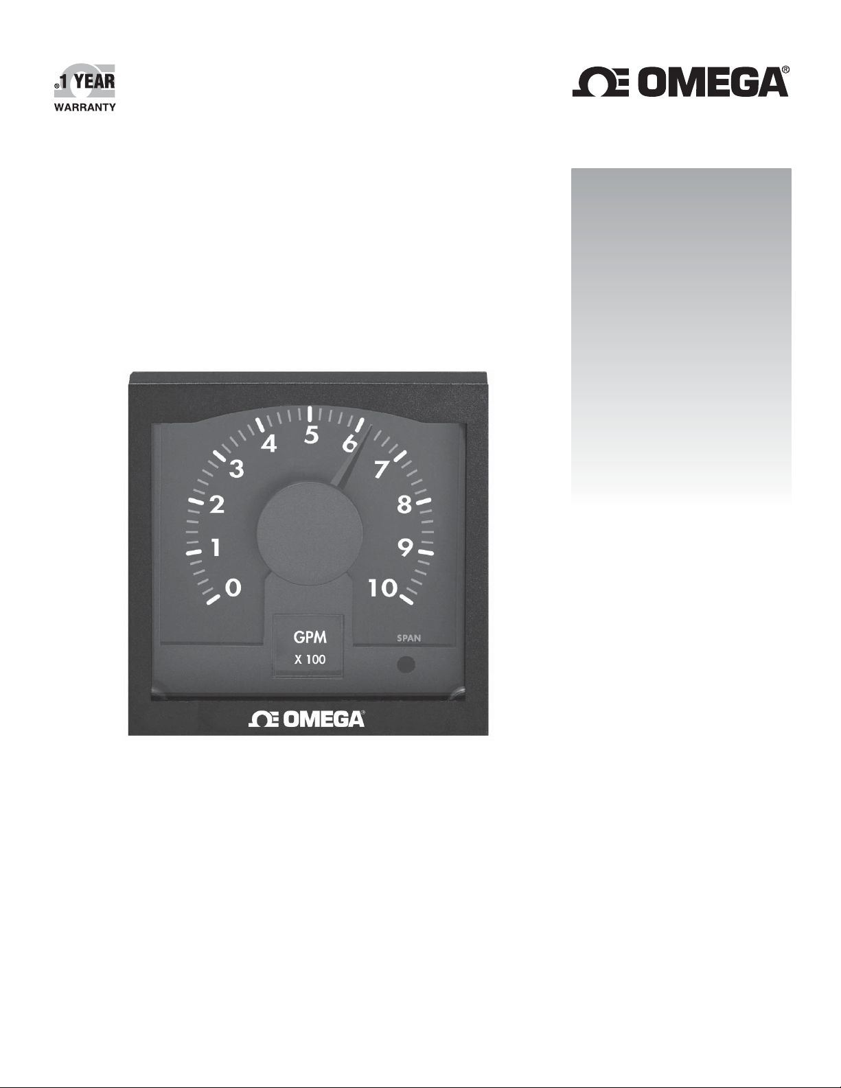
FPM-5800
Flow Indicator
Page 2

omega.com [email protected]
Servicing North America:
U.S.A. Omega Engineering, Inc.
Headquarters: Toll-Free: 1-800-826-6342 (USA & Canada only)
Customer Service: 1-800-622-2378 (USA & Canada only)
Engineering Service: 1-800-872-9436 (USA & Canada only)
Tel: (203) 359-1660 Fax: (203) 359-7700
e-mail: [email protected]
For Other Locations Visit omega.com/worldwide
The information contained in this document is believed to be correct, but OMEGA accepts no liability for any errors it contains, and reserves
the right to alter specifications without notice.
Page 3
Red
Blk
Shld
Sensor
Input
FP-5100
FP-5300
Black (AC signal out)
Red (AC signal out)
Silver (shield)
FPM-5800
LPM
x 1,000
GPM
x 10
m3/h
SPAN
0
1
2
3
8
6
7
5
4
9
10
SPAN
0
1
2
SPAN
0
1
2
SPAN
0
1
2
3
8
6
7
5
4
9
10
OMEGA FPM-5800 Flow Indicator Instructions
Red
Blk
Shld
Sensor
Input
Red
Blk
Shld
Sensor
Input
LISTED
77CJ
U
L
CAUTION!
Follow instructions carefully to avoid personal injury.
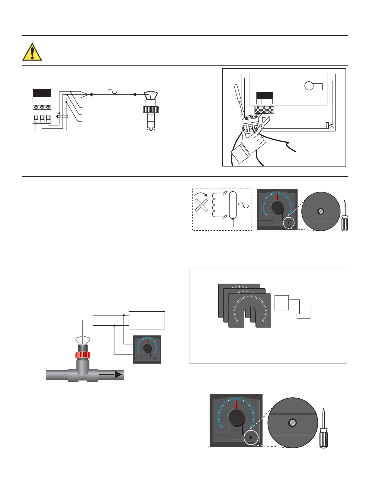
1. Compatible Sensor Wiring
Technical Notes:
• Remove terminal block for easy wiring (Fig. 1).
• Maintain cable shield through cable splice.
• Route sensor cable away from AC power lines.
• Use 2-conductor shielded cable for sensor cable splices up to 60 m (200 ft)
Fig. 1
2. Calibration
The FPM-5800 fl ow metering system utilizes the AC signal amplitude
from the FP-5100 or FP-5300 sensor to drive the FPM-5800 meter.
The front panel meter movement adjustment (SPAN) is easily
accessed under the removable front window for simple calibration.
A dial kit with six dial ranges, assorted fl ow unit/multiplier decals and
dial installation instructions is included for your convenience.
Equipment Required
• Frequency counter
• OMEGA FP-5100 or FP-5300 Sensor installed in the process line
• Maximum (stable) fl ow rate induced in the process line
• Standard and phillips head screwdriver
Procedure
1. Induce the maximum (stable) fl ow rate in your process line.
2. Using the frequency counter, monitor and record the FP-5100 or
FP-5300 sensor frequency output (Hz), see diagram below:
Red
Frequency
Black
counter
5
4
6
3
7
2
1
10
0
GPM
X100
8
9
SPAN
FP-5100 or FP-5300 Circuit
Red
lack
Rotor
w/magnets
Shield
FPM-5800
5
4
3
2
1
0
GPM
X 100
6
8
10
SPAN
SPAN
4. Install the appropriate dial face and fl ow unit/multiplier decal
covering your fl ow system's maximum fl ow rate (step 3).
Refer to dial installation instructions included with dial kit.
Your instrument dial kit (included) contains the following:
6 Dials:
0-2
0-4
0-6
0-8
0-10
0-100
Assorted
Unit/multiplier
Decals:
X 10
X 100
X 1,000
X 10,000
Example: A fl ow system's maximum fl ow rate is 18.3 GPM.
The proper dial and fl ow unit/multiplier decal for this fl ow
system is:
0 - 2 dial + GPM X 10 decal
Sensor Frequency = ___________________________ Hz
Technical note:
Sensor frequency MUST be greater than 45 Hz for full scale needle
defl ection.
3. Calculate the actual maximum fl ow rate in your process line as follows:
Maximum fl ow rate = Sensor frequency (step 2) X A-Factor (Section 6)
Maximum Flow rate = ___________________________________
5. Disconnect frequency counter, then access and adjust the
"SPAN" potentiometer to match the calculated maximum fl ow rate
(step 3). After adjustment, calibration is complete.
5
6
4
3
2
1
0
GPM
X 100
8
10
SPAN
SPAN
1Omega FPM-5800 Flow Indicator
Page 4
I I
Monting lam 2 ea
Otional laroo ear oer
88 mm
5 in
Monting Panel
Panel
aet
mm
in
mm in
88 mm 5 in
mm 8 in
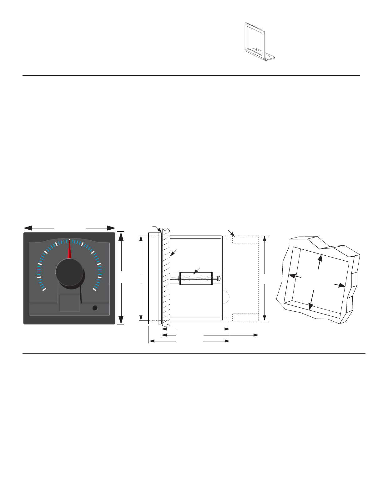
3. Parts and Accessories
92 x 92 mm
(3.62 x 3.62 in.)
Panel cutout
There are no user-replaceable components in the FPM-5800.
Unauthorized repair attempts may void warranty.
Optional surface mount bracket, FPM-5000-MB
4. Specifi cations
General
Sensor compatibility: OMEGA FP-5100 & FP-5300 series only
Min. full scale range: 7 fps
Enclosure:
• Rating: NEMA 4X/IP65 front
• Dimensions: 1/4 DIN, 96 x 96 x 88 mm (3.8 x 3.8 x 3.5 in.)
• Case: ABS plastic
• Weight: Approximately 450 g (16 oz.)
Display:
• Type: Taut-band suspension meter movement,
250° defl ection (not suitable for prolonged
exposure to vibration)
• Accuracy: ±2% of full scale
• Repeatability: ±1% of full scale
96 mm (3.8 in.)
5
4
3
2
1
0
6
7
8
9
96 mm
(3.8 in.)
10
Dimensions
Environmental
Operating temp.: -10 to 65 °C (14 to 149 °F)
Storage temp.: -15 to 80 °C (5 to 176 °F)
Relative humidity: 0 to 95%, non-condensing
Quality Standards
• FM, CSA, CE, UL listed
• Manufactured under ISO 9001
Electrical
Power: None
Noise immunity: EN50082-2
Noise emissions: EN55011
Safety: EN61010-1
GPM
X 100
SPAN
Front View
5. Maintenance
• Front window: Never wipe the front window with materials
such as wool or polyester which may induce a static charge.
If a static charge develops on the window, the indication
needle may appear erratic or non-functional. When this
occurs, clean the front window with an anti-static cloth, or a
soft cotton cloth and anti-static spray, or a mild liquid soap
solution to remove the static charge.
2 Omega FPM-5800 Flow Indicator
• Case: Clean the instrument case and front panel with a soft
cotton cloth dampened with a mild liquid soap solution.
Page 5
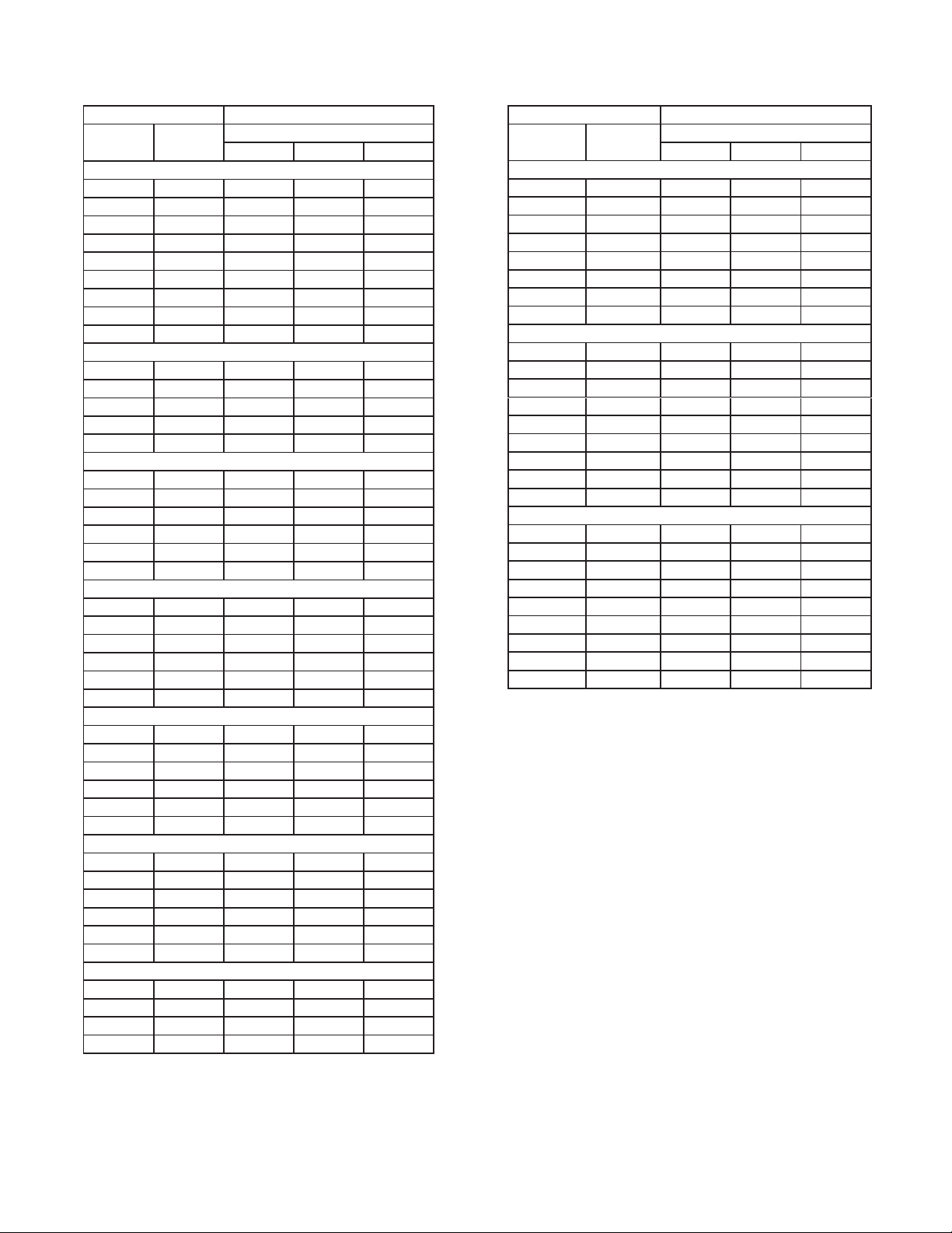
6. OMEGA FP-5100 or FP-5300 Flow Sensor A-Factors
-------------- A-FACTORS ----------------
PIPE
SIZE
1/2 IN. FP-5305M 0.1250 0.4729 0.0284
3/4 IN. FP-5307M 0.2328 0.8812 0.0529
1 IN. FP-5310M 0.3435 1.3002 0.0780
1-1/4 IN. FP-5312M 0.7195 2.7233 0.1634
1-1/2 IN. FP-5315M 1.0242 3.8767 0.2326
2 IN. FP-5320M 1.8473 6.9920 0.4195
2-1/2 IN. FP-5325M 2.7481 10.4016 0.6241
3 IN. FP-5330M 4.4310 16.7714 1.0063
4 IN. FP-5340M 7.8681 29.7807 1.7868
SCH 80 CPVC TEES FOR SCH 80 CPVC PIPE
1/2 IN. FP-5305CM 0.1250 0.4729 0.0284
3/4 IN. FP-5307CM 0.2328 0.8812 0.0529
1 IN. FP-5310CM 0.3435 1.3002 0.0780
1-1/4 IN. FP-5312CM 0.7195 2.7233 0.1634
1-1/2 IN. FP-5315CM 1.0242 3.8767 0.2326
SCH 80 PVC SADDLES FOR SCH 80 PVC PIPE
2 IN. FP-5320S 1.8473 6.9920 0.4195
2-1/2 IN. FP-5325S 2.7481 10.4016 0.6241
3 IN. FP-5330S 4.4310 16.7714 1.0063
4 IN. FP-5340S 7.8681 29.7807 1.7868
6 IN. FP-5360S 14.4152 54.5614 3.2737
8 IN. FP-5380S 25.3115 95.8039 5.7482
SCH 80 PVC SADDLE ON SCH 40 PVC PIPE
2 IN. FP-5320S 2.1938 8.3035 0.4982
2-1/2 IN. FP-5325S 3.1789 12.0321 0.7219
3 IN. FP-5330S 4.7477 17.9702 1.0782
4 IN. FP-5340S 8.9177 33.7536 2.0252
6 IN. FP-5360S 16.0871 60.8897 3.6534
8 IN. FP-5380S 27.8714 105.4932 6.3296
CARBON STEEL TEES ON SCH 40 PIPE
1/2 IN. FP-5305CS 0.1621 0.6134 0.0368
3/4 IN. FP-5307CS 0.2829 1.0709 0.0643
1 IN. FP-5310CS 0.4251 1.6091 0.0965
1-1/4 IN. FP-5312CS 0.9892 3.7442 0.2246
1-1/2 IN. FP-5315CS 1.3230 5.0077 0.3005
2 IN. FP-5320CS 2.2416 8.4845 0.5091
STAINLESS STEEL TEES ON SCH 40 PIPE
1/2 IN. FMG-5305 0.1671 0.6327 0.0380
3/4 IN. FMG-5307 0.2961 1.1209 0.0673
1 IN. FMG-5310 0.4719 1.7862 0.1072
1-1/4 IN. FMG-5312 0.9691 3.6682 0.2201
1-/2 IN. FMG-5315 1.4848 5.6199 0.3372
2 IN. FMG-5320 2.6906 10.1839 0.6110
GALVANIZED IRON TEES ON SCH 40 PIPE
1 IN. FP-5310GI 0.5740 2.1724 0.1303
1-1/4 IN. FP-5312GI 0.9527 3.6060 0.2164
1-1/2 IN. FP-5315GI 1.2851 4.8642 0.2919
2 IN. FP-5320GI 2.0367 7.7089 0.4625
OMEGA
FITTING
SCH 80 PVC TEES FOR SCH 80 PVC PIPE
------------------- 1 Hz = -------------------
U.S. GPM LPM m3/h
----------------- A-FACTORS -------------------
PIPE
SIZE
COPPER/BRONZE BRAZOLETS ON SCH 40 PIPE
2-1/2 IN. FP-5325BR 3.1915 12.0798 0.7248
3 IN. FP-5330BR 4.9302 18.6606 1.1196
4 IN. FP-5340BR 8.6207 32.6293 1.9578
5 IN. FP-5350BR 11.4068 43.1749 2.5905
6 IN. FP-5360BR 16.2602 61.5447 3.6927
8 IN. FP-5380BR 28.1690 106.6197 6.3972
10 IN. FP-5381BR 44.4444 168.2222 10.0933
12 IN. FP-5382BR 62.5000 236.5625 14.1938
SCH 80 IRON SADDLES ON SCH 80 PIPE
2 IN. FP-5320GIS 1.8541 7.0179 0.4211
2 1/2 IN. FP-5325GI 2.7003 10.2205 0.6132
3 IN. FP-5330GI 4.4709 16.9225 1.0154
4 IN. FP-5340GI 7.8329 29.6475 1.7789
5 IN. FP-5350GI 10.2389 38.7543 2.3253
6 IN. FP-5360GI 14.6699 55.5257 3.3315
8 IN. FP-5380GI 25.7511 97.4678 5.8481
10 IN. FP-5381GI 39.2157 148.4314 8.9059
12 IN. FP-5382GI 56.6038 214.2453 12.8547
SCH 80 IRON SADDLE ON SCH 40 PIPE
2 IN. FP-5320GIS 2.2371 8.4676 0.5081
2-1/2 IN. FP-5325GI 3.1915 12.0798 0.7248
3 IN. FP-5330GI 5.0042 18.9408 1.1364
4 IN. FP-5340GI 8.7591 33.1533 1.9892
5 IN. FP-5350GI 11.2570 42.6079 2.5565
6 IN. FP-5360GI 15.9574 60.3989 3.6239
8 IN. FP-5380GI 28.1690 106.6197 6.3972
10 IN. FP-5381GI 44.4444 168.2222 10.0933
12 IN. FP-5382GI 62.5000 236.5625 14.1938
OMEGA
FITTING
---------------------- 1 Hz = ----------------------U.S. GPM LPM m3/h
A-Factor Conversion Formulas:
1 U.S. gallon =
0.83267 Imperial gallon
0.003785 cubic meters
0.000003069 Acre feet
8.3454 pounds of water
3Omega FPM-5800 Flow Indicator
Page 6
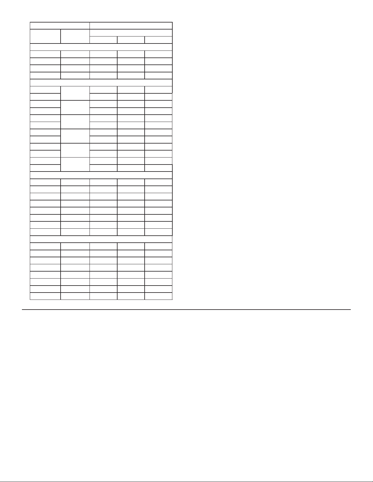
----------------- A-FACTORS -------------------
PIPE
SIZE
BRONZE TEES ON SCH 40 PIPE
1 IN. FP-5310BR 0.5740 2.1724 0.1303
1-1/4 IN. FP-5312BR 0.9527 3.6060 0.2164
1-1/2 IN. FP-5315BR 1.2851 4.8642 0.2919
2 IN. FP-5320BR 2.0367 7.7089 0.4625
COPPER TEE FITTINGS ON COPPER PIPE
1/2 IN.SK K
1/2 IN. SK L 0.1448 0.5480 0.0329
3/4 IN.SK K
3/4 IN. SK L 0.3140 1.1885 0.0713
1 IN.SK K
1 IN. SK L 0.5007 1.8950 0.1137
1-1/4 IN.SK K
1-1/4 IN. SK L 0.7022 2.6577 0.1595
1-1/2 IN.SK K
1-1/2 IN. SK L 1.0878 4.1171 0.2470
2 IN.SK K
2 IN. SK L 2.0975 7.9391 0.4763
STAINLESS STEEL WELDOLETS ON SCH 40 PIPE
2-1/2 IN. FMG-5325 3.1915 12.0798 0.7248
3 IN. FMG-5330 4.9302 18.6606 1.1196
4 IN. FMG-5340 8.6207 32.6293 1.9578
5 IN. FMG-5350 11.4068 43.1749 2.5905
6 IN. FMG-5360 16.2602 61.5447 3.6927
8 IN. FMG-5380 28.1690 106.6197 6.3972
10 IN. FMG-5381 44.4444 168.2222 10.0933
12 IN. FMG-5382 62.5000 236.5625 14.1938
CARBON STEEL WELDOLETS ON SCH 40 PIPE
2-1/2 IN. FP-5325CS 3.1915 12.0798 0.7248
3 IN. FP-5330CS 4.9302 18.6606 1.1196
4 IN. FP-5340CS 8.6207 32.6293 1.9578
5 IN. FP-5350CS 11.4068 43.1749 2.5905
6 IN. FP-5360CS 16.2602 61.5447 3.6927
8 IN. FP-5380CS 28.1690 106.6197 6.3972
10 IN. FP-5381CS 44.4444 168.2222 10.0933
12 IN. FP-5382CS 62.5000 236.5625 14.1938
OMEGA
FITTING
FP-5305CU
FP-5307CU
FP-5310CU
FP-5312CU
FP-5315CU
FP-5320CU
---------------------- 1 Hz = ----------------------U.S. GPM LPM m3/h
0.1354 0.5124 0.0307
0.2828 1.0704 0.0642
0.4718 1.7857 0.1071
0.6801 2.5743 0.1545
1.0533 3.9869 0.2392
2.0429 7.7325 0.4639
A-Factor Conversion Formulas:
1 U.S. gallon =
0.83267 Imperial gallon
0.003785 cubic meters
0.000003069 Acre feet
8.3454 pounds of water
4 Omega FPM-5800 Flow Indicator
Page 7

WARRANTY/DISCLAIMER
OMEGA ENGINEERING, INC. warrants this unit to be free of defects in materials and workmanship for a
period of 13 months from date of purchase. OMEGA’s WARRANTY adds an additional one (1) month
grace period to the normal one (1) year product warranty to cover handling and shipping time. This
ensures that OMEGA’s customers receive maximum coverage on each product.
If the unit malfunctions, it must be returned to the factory for evaluation. OMEGA’s Customer Service
Department will issue an Authorized Return (AR) number immediately upon phone or written request.
Upon examination by OMEGA, if the unit is found to be defective, it will be repaired or replaced at no
charge. OMEGA’s WARRANTY does not apply to defects resulting from any action of the purchaser,
including but not limited to mishandling, improper interfacing, operation outside of design limits,
improper repair, or unauthorized modification. This WARRANTY is VOID if the unit shows evidence of
having been tampered with or shows evidence of having been damaged as a result of excessive corrosion;
or current, heat, moisture or vibration; improper specification; misapplication; misuse or other operating
conditions outside of OMEGA’s control. Components in which wear is not warranted, include but are not
limited to contact points, fuses, and triacs.
OMEGA is pleased to offer suggestions on the use of its various products. However,
OMEGA neither assumes responsibility for any omissions or errors nor assumes liability for
any damages that result from the use of its products in accordance with information provided
by OMEGA, either verbal or written. OMEGA warrants only that the parts manufactured by the
company will be as specified and free of defects. OMEGA MAKES NO OTHER WARRANTIES OR
REPRESENTATIONS OF ANY KIND WHATSOEVER, EXPRESSED OR IMPLIED, EXCEPT THAT OF
TITLE, AND ALL IMPLIED WARRANTIES INCLUDING ANY WARRANTY OF MERCHANTABILITY
AND FITNESS FOR A PARTICULAR PURPOSE ARE HEREBY DISCLAIMED. LIMITATION OF
LIABILITY: The remedies of purchaser set forth herein are exclusive, and the total liability of
OMEGA with respect to this order, whether based on contract, warranty, negligence,
indemnification, strict liability or otherwise, shall not exceed the purchase price of the
component upon which liability is based. In no event shall OMEGA be liable for
consequential, incidental or special damages.
CONDITIONS: Equipment sold by OMEGA is not intended to be used, nor shall it be used: (1) as a “Basic
Component” under 10 CFR 21 (NRC), used in or with any nuclear installation or activity; or (2) in medical
applications or used on humans. Should any Product(s) be used in or with any nuclear installation or
activity, medical application, used on humans, or misused in any way, OMEGA assumes no responsibility
as set forth in our basic WARRANTY/D ISCLAIMER language, and, additionally, purchaser will indemnify
OMEGA and hold OMEGA harmless from any liability or damage whatsoever arising out of the use of the
Product(s) in such a manner.
RETURN REQUESTS/INQUIRIES
Direct all warranty and repair requests/inquiries to the OMEGA Customer Service Department.
BEFORE RETURNING ANY PRODUCT(S) TO OMEGA, PURCHASER MUST OBTAIN AN AUTHORIZED
RETURN (AR) NUMBER FROM OMEGA’S CUSTOMER SERVICE DEPARTMENT (IN ORDER TO AVOID
PROCESSING DELAYS). The assigned AR number should then be marked on the outside of the return
package and on any correspondence.
The purchaser is responsible for shipping charges, freight, insurance and proper packaging to prevent
breakage in transit.
FOR WARRANTY RETURNS, please have the
following information available BEFORE contacting
OMEGA:
1. Purchase Order number under which the product
was PURCHASED,
2. Model and serial number of the product under
warranty, and
3. Repair instructions and/or specific problems
relative to the product.
OMEGA’s policy is to make running changes, not model changes, whenever an improvement is possible. This affords
our customers the latest in technology and engineering.
OMEGA is a registered trademark of OMEGA ENGINEERING, INC.
© Copyright 2016 OMEGA ENGINEERING, INC. All rights reserved. This document may not be copied, photocopied,
reproduced, translated, or reduced to any electronic medium or machine-readable form, in whole or in part, without the
prior written consent of OMEGA ENGINEERING, INC.
FOR NON-WARRANTY REPAIRS,
OMEGA for current repair charges. Have
the following information available BEFORE
contacting OMEGA:
1. Purchase Order number to cover the COST
of the repair,
2. Model and serial number of the product, and
3. Repair instructions and/or specific problems
relative to the product.
consult
Page 8

Where Do I Find Everything I Need for
Process Measurement and Control?
OMEGA…Of Course!
Shop online at omega.com
TEMPERATURE
Thermocouple, RTD & Thermistor Probes, Connectors, Panels & Assemblies
Wire: Thermocouple, RTD & Thermistor
Calibrators & Ice Point References
Recorders, Controllers & Process Monitors
Infrared Pyrometers
PRESSURE, STRAIN AND FORCE
Transducers & Strain Gages
Load Cells & Pressure Gages
Displacement Transducers
Instrumentation & Accessories
FLOW/LEVEL
Rotameters, Gas Mass Flowmeters & Flow Computers
Air Velocity Indicators
Turbine/Paddlewheel Systems
Totalizers & Batch Controllers
SM
pH/CONDUCTIVITY
pH Electrodes, Testers & Accessories
Benchtop/Laboratory Meters
Controllers, Calibrators, Simulators & Pumps
Industrial pH & Conductivity Equipment
DATA ACQUISITION
Communications-Based Acquisition Systems
Data Logging Systems
Wireless Sensors, Transmitters, & Receivers
Signal Conditioners
Data Acquisition Software
HEATERS
Heating Cable
Cartridge & Strip Heaters
Immersion & Band Heaters
Flexible Heaters
Laboratory Heaters
ENVIRONMENTAL
MONITORING AND CONTROL
Metering & Control Instrumentation
Refractometers
Pumps & Tubing
Air, Soil & Water Monitors
Industrial Water & Wastewater Treatment
pH, Conductivity & Dissolved Oxygen Instruments
M2575/0916
 Loading...